Basic Information
Receive sensor information on a gigabit network!


 |  |
|---|---|
 |
Features

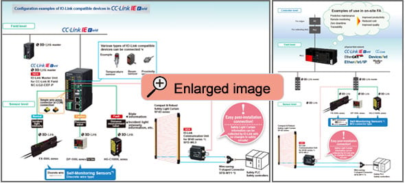
Smart collection of on-site sensor information
Collecting on-site sensor-level information is essential to making the manufacturing floor “visible” and IoT enabled.
Panasonic Industry provides an information collection solution that is easy, low-cost, and maintains information quality.
Using Panasonic Industry's self-monitoring sensors and IO-Link master, incident light intensity, pressure values, and distance measurement values can be sent as digital data with certitude to a host controller.
The sensors diagnose their own state and inform you of the result, making it easy to identify the cause of problems.
By reducing the amount of data collected, you can alleviate the labor spent organizing and analyzing data.
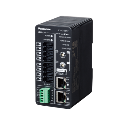
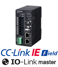
IO-Link Master Unit [SC-LG2-CEF-P]
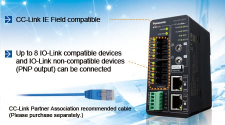
CC-Link IE Field compatible
Can be used as an intelligent device station.
Up to 8 IO-Link compatible devices and IO-Link non-compatible devices (PNP output) can be connected
As an IO-Link master, the unit supports up to 8 connection channels.
Simple wire-press connector (e-CON) enables easy connection
Available as an option (sold separately).
IO-Link device settings can be set at once from the host tool
Settings can be configured at once from the host tool (SC-LG-CEF Configuration Tool) via a Mitsubishi Electric Corporation PLC.

Device monitor screen
Order guide
IO-link master unit
Simple wire-press connector (e-CON) is not included with the IO-Link master unit. Please purchase separately.
| Type | Model No. | Description |
|---|---|---|
| IO-Link master unit for CC-Link IE Field
| SC-LG2-CEF-P | By connecting this to an IO-Link compatible device, you can acquire measurement data and set and acquire parameters from CC-Link IE Field communication. You can also connect this to an IO-Link non-compatible device (PNP output) that has digital input / output functions (ON/OFF signal). You can acquire the input state of the ON/OFF signal of the IO-Link non-compatible device from CC-Link IE Field communication, and output the ON/OFF signal to the IO-Link non-compatible device. |
IO-Link compatible devices
For details on each sensor, refer to our website.
- Digital Fiber Sensor FX-550L (Discrete wire type)
- Dual Display Digital Pressure Sensor [For Gas] DP-100L (Discrete wire type)
- CMOS Type Micro Laser Distance Sensor HG-C1000L (Discrete wire type)
- Cylindrical Inductive Proximity Sensor [Amplifier Built-in / DC 3-wire Type] GX-300 (M8/M12/M18/M30 Threaded, Normally open type)
Option
| Type | Appearance | Model No. | Description |
|---|---|---|---|
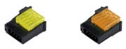
| Simple wire-press connector (e-CON) |
| CN-EP2 | • Applicable wire: 0.1 to 0.5 mm2 (AWG27 to 20) • Wire diameter without jacket: ø1.0 to ø1.15 mm ø0.039 to ø0.045 in • Plug housing color: Yellow [5 pcs. per set] |
| CN-EP3 | • Applicable wire: 0.1 to 0.5 mm2 (AWG27 to 20) • Wire diameter without jacket: ø0.6 to ø0.9 mm ø0.024 to ø0.035 in • Plug housing color: Orange [5 pcs. per set] |


IO-Link communication unit for SF4D series
SFD-WL3
For details, refer to "Compact & Robust Safety Light Curtain [Type 4 PLe SIL3] SF4D" page.

Recommended simple wirepress connector (e-CON)
TE Connectivity Japan G.K.
Model: 1473562-4
Note: Contact the manufacturer for details of the recommended products.
Recommended power connector
PHOENIX CONTACT
Product code: Equivalent to MC1.5/5-ST-3.5AU
Note: Contact the manufacturer for details of the recommended products.
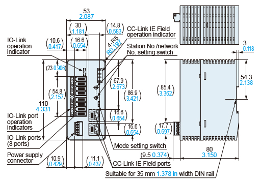
Dimensions
Unit: mm inSC-LG2-CEF-P
IO-Link master unit for CC-Link IE Field