------------------------------ Tab1 showing ------------------------------
Basic Information
Capable of diagnosing own state and reporting to the host device


![]()
 |  |
|---|---|
 |
Features
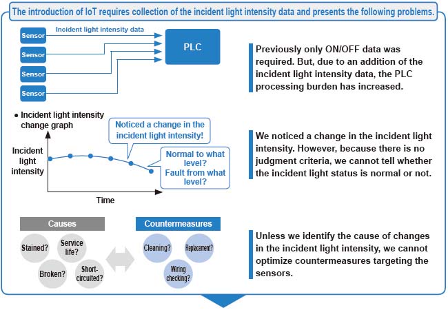
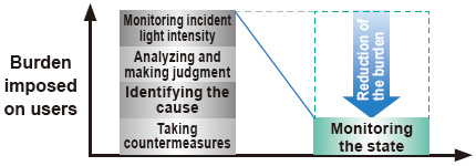
Reduction of the data analysis burdenone small step towards IoT.
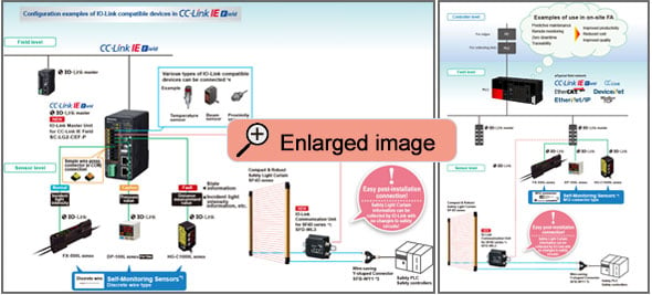
IO-Link compatible Collecting sensor level data
Field data collected and accumulated for “preventive maintenance” and “operation monitoring”.
An analysis of such field data requires high-level know-how and time, causing a burden to people responsible for the production site management.
The Self-Monitoring Sensor manufactured by Panasonic is capable of reporting sensor data and its own state to the host device through the I/O Link master.
With the Self-Monitoring Sensor, you can immediately judge the state of the sensor and easily identify the cause of failure. Thus, this sensor contributes to the reduction of the burden experienced by the client in collecting and analyzing data.
Incorporated self-monitoring function
With the Panasonic's Self-Monitoring Sensor,you can get high-level solutions!
Problems are solved by the Self-monitoring function.
| Status | Judgement of the state | ||
|---|---|---|---|
| Normal | Operation is normal. | ||
| Notification | Check the settings. Detected state is faulty. | * Recover to the normal state through checking installation and settings. Reduction in the incident light intensity | |
| Caution | Getting close to the end of service life. Reached the state where the device should be replaced. | * Limitation in the writing frequency into the memory or in the operation hours, etc. | |
| Fault | Short-circuited or broken. Reached the state where it is impossible to control as a device. | * Short-circuited output, damaged EEPROM, etc. | |
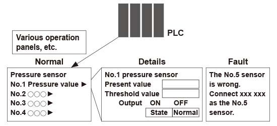
*
By creating a program with a PLC, etc., the "State" of the self-monitoring sensor can be grasped.
Software are available for download. *Membership registration is required to access/download this data.
>>Go to Data download.
Easy use of IoT
“Predictive maintenance” can be easily achieved through monitoring the state of the Self-Monitoring Sensor.
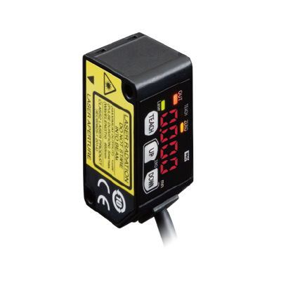
<Compact>
The smallest CMOS laser sensor in the industry*
*Based on research conducted by our company as of July 2022
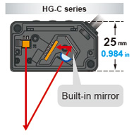
A new optical system with a built-in mirror
In general, more accurate and stable measurements can be obtained by increasing the optical path length between the light-receiving part and the light receiving element (CMOS), but this also increases the sensor depth and the sensor body gets bigger. The HG-C series sensors incorporating a new optical system with a built-in mirror provides smaller sensor depth as well as higher measurement accuracy equivalent to displacement sensors.
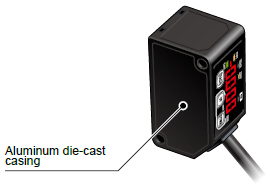
An aluminum die-cast casing protects from strain and heat
A light-weight but strong die-cast aluminum casing has been adopted. A compact, solid body casing reduces the impact of strain and heat on the measurement accuracy.
<Overwhelmingly stable>
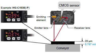
Precise measurements on the order of 1/100 mm 0.0003 inch*
* HG-C1030□
Fitted with a precise CMOS image sensor and an original algorithm
Thanks to a precise CMOS image sensor, it is now possible to perform highly precise measurements in the order of 1/100 mm 0.0003 in. The existing adjustable range reflective sensors cannot achieve such accuracy.
Useful functions
Teaching & window comparator mode
Normal sensing mode
[2-Point teaching]
Basic teaching method
The threshold value is set automatically at the midpoint between the two points specified by teaching.
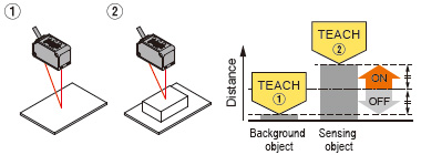
[Limit teaching]
Useful teaching method for when there is a very small object or background object.
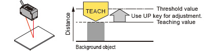
<When using background object as reference>
When the sensing object is located closer to the sensor than the background object, the threshold value for detection is set. This function is useful when there is a change in the size of sensing object.
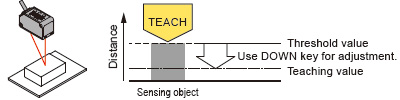
<When using sensing object as reference>
The threshold value is set on the background object side with reference to the sensing object. Use this method when there is a long distance to the background object.
Window comparator mode
With an object below the sensor, press the TEACH key to set the valid range for distances via threshold values. There are 3 methods for setting the valid range: 1-point, 2-point, and 3-point teaching.
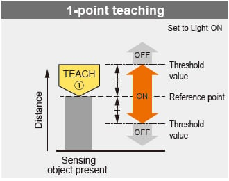
Perform 1-point teaching and the threshold range is set for the distance from the reference surface of the sensing object.
This is used for sensing within the threshold range.
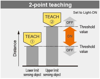
Press TEACH once for the lower (first point) and once for the upper limit (second point).
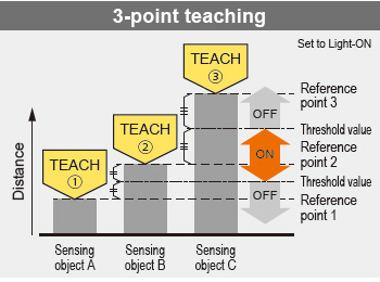
This is the method to set the threshold range by conducting the teaching at 3 points (sensing object A, B and C). After teaching, the reference points are automatically sorted in ascending order (reference point 1, 2 and 3). The thresholds are set at the midpoints between reference point 1 and 2, and 2 and 3, respectively.
Rising differential mode / Trailing differential mode
Use this mode to cancel gradual changes in the measured value and to detect only sudden changes. For the setting of threshold value, use the threshold value fine adjustment function.
Timer setting function
The time mode options are “off-delay timer,” “on-delay timer,” “one-shot timer” and “no timer.” The counting time is fixed to 5 ms.
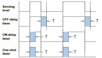
Off-delay timer
Function : Extends output signals by 5 ms.
Usage : Appropriate in case a connected device is slow to respond and ON time is required to extend.
On-delay timer
Function: Overrides output signals for 5 ms after detection.
Usage: Convenient way to override temporary signals and control with a time lag.
One-shot timer
Function: Sends output signals for only 5 ms after detection.
Usage: Useful when the signal duration needs to be constant to meet inputs from a connected device.
This mode is also used to extend temporary signals by a desired length of time.
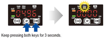
Zero set function
This function compulsorily sets the measured value to “zero.”
The zero point can be set at a desired value. It is useful when measuring steps or tolerance with reference to the height of a sensing object.
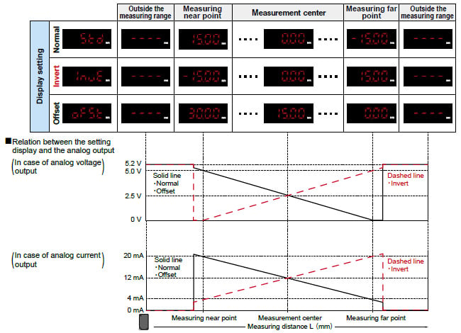
Display setting function
How to indicate measured values of the moving sensed object can be chosen from three options, “Normal,” “Invert” and “Offset.”
Example:HG-C1050(-P)
Peak and bottom hold functions
The peak hold function holds the maximum measured value which is output and displayed.
The bottom hold function holds the minimum measured value which is output and displayed.
* The peak hold function and the bottom hold function cannot be set at the same time.
* When the zero set function is executed while the peak hold function or the bottom hold function is valid, the held measurement value is reset.
Threshold value fine adjustment function
Fine adjustment of threshold values can be performed while measurement is proceeding on the display, and even after teaching.
Key lock function
This function protects setting conditions from unintentional changes.
* For other functions and procedures for setting the functions, see“PRO Mode Setting”.
------------------------------ Tab2 showing ------------------------------
Applications
IoT Examples at FA Sites
Before the introduction of Self-Monitoring Sensors
Preventive maintenance
●We want to avoid production line stoppage that might occur due to unexpected sensor failure.
Line stoppage hours × (manufacturing unit cost / hour) = Loss
●We want to minimize the production line down time to almost zero.
Problems
◆The amount of data to be collected is large and this may lower the PLC processing capacity.
◆The burden of data analysis is large.
◆Resetting the replaced sensors is troublesome.

After the introduction of Self‑Monitoring Sensors
From preventive maintenance to predictive maintenance
Leave the sensor diagnosis to the sensor itself.
●All you need to do is to monitor the sensor state.
●PLC can be used exclusively for controlling devices.
●Possible to check detail information at a desired timing.
Leave the resetting for replaced sensors to the higher-level master
●Automatically written from the connected master.
●Possible not only to save time but also to prevent human errors.
IoT Examples at FA Sites 02
Before the introduction of Self-Monitoring Sensors
Remote controlling and batch settings
●We want to place sensors close to sensing points as much as possible.
However, it is often difficult to make settings, particularly when there are many sensors to install.
●We want to send predetermined parameter values in a batch file for a repeater, etc.
●We want to confirm that required sensors are properly connected at the startup of the system.

Problems
◆It takes time to set sensors.
◆We want to avoid mistakes in setting sensors or wiring.

After the introduction of Self‑Monitoring Sensors
Fully utilize the advantages of the IO‑Link output.
●Possible to read or write set values through external
interface.
●Possible to set multiple sensors in a batch process.
●Possible to save the set parameters in an external medium.
●Possible to recognize and discriminate individual information.
------------------------------ Tab3 showing ------------------------------
Order guide
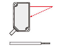
Discrete wire type
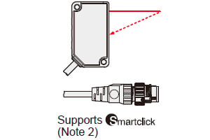
M12 connector type
Note)Smartclick is a trademark or registered trademark of OMRON Corporation.
Discrete wire type
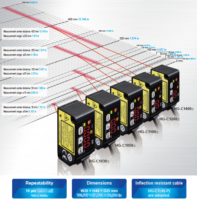
| Type | Measurement center distance and measurement range | Repeatability | Beam diameter (Note) | Model No. | Control output |
|---|---|---|---|---|---|
| Measurement center 30 mm 1.181 in type | 30±5mm 1.181 ±0.197 in | 10μm 0.394 mil | ø50μm 1.969 mil approx. | HG-C1030L3-P | PNP opencollector transistor |
| Measurement center 50 mm 1.969 in type | 50±15mm 1.969 ±0.591 in | 30μm 1.181 mil | ø70μm 2.756 mil approx. | HG-C1050L3-P | |
| Measurement center 100 mm 3.937 in type | 100±35mm 3.937 ±1.328 in | 70μm 2.756 mil | ø120μm 4.724 mil approx. | HG-C1100L3-P | |
| Measurement center 200 mm 7.874 in type | 200±80mm 7.874 ±3.150 in | 200μm 7.874 mil | ø300μm 11.811 mil approx. | HG-C1200L3-P | |
| Measurement center 400 mm 15.748 in type | 400±200mm 15.748 ±7.874 in | 300μm 11.811 mil (Measuring distance 200~400mm 7.874 to 15.748 in) 800μm 31.496 mil (Measuring distance 400~600mm 15.748 to 23.622 in) | ø500μm 19.685 mil approx. | HG-C1400L3-P |
M12 connector type
| Type | Measurement center distance and measurement range | Repeatability | Beam diameter (Note) | Model No. | Control output |
|---|---|---|---|---|---|
| Measurement center 30 mm 1.181 in type | 30±5mm 1.181 ±0.197 in | 10μm 0.394 mil | ø50μm 1.969 mil approx. | HG-C1030L3-P-J | PNP opencollector transistor |
| Measurement center 50 mm 1.969 in type | 50±15mm 1.969 ±0.591 in | 30μm 1.181 mil | ø70μm 2.756 mil approx. | HG-C1050L3-P-J | |
| Measurement center 100 mm 3.937 in type | 100±35mm 3.937 ±1.328 in | 70μm 2.756 mil | ø120μm 4.724 mil approx. | HG-C1100L3-P-J | |
| Measurement center 200 mm 7.874 in type | 200±80mm 7.874 ±3.150 in | 200μm 7.874 mil | ø300μm 11.811 mil approx. | HG-C1200L3-P-J | |
| Measurement center 400 mm 15.748 in type | 400±200mm 15.748 ±7.874 in | 300μm 11.811 mil (Measuring distance 200~400mm 7.874 to 15.748 in) 800μm 31.496 mil (Measuring distance 400~600mm 15.748 to 23.622 in) | ø500μm 19.685 mil approx. | HG-C1400L3-P-J |
Notes:
1)This is the size in the measurement center distance. These values were defined by using 1/e2 (13.5% approx.) of the center light intensity.
Due to leak light outside the specified area, the reflectance around the detecting point may be higher than at the point and this may affect the measurement value.
2)Smartclick is a trademark or registered trademark of OMRON Corporation.
------------------------------ Tab4 showing ------------------------------
Option
| Designation | Model No. | Description |
|---|---|---|
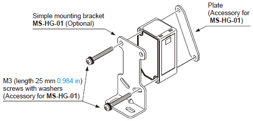
| Simple mounting bracket (Note) | MS-HG-01 | Foot angled mounting bracket |
Note:
Due to the simple mounting bracket, the sensing characteristics may not be hold depending on the
installation condition, in case of the purposes for acquiring the displacement data and a fine
detecting.
Simple mounting bracket
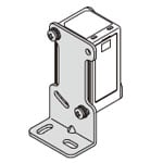
Material: Stainless steel (SUS304)Two M3 (length 25 mm0.984 in) screws with washers (SPCC) are attached.
Recommended extension cables for M12 connector type
Manufactured by OMRON Corporation
Extension cable with connectors on both ends XS5W series
![]()
※Smartclick is a trademark or registered trademark of OMRON Corporation. Please contact the manufacturer for details of the recommended products.
------------------------------ Tab5 showing ------------------------------
------------------------------ Tab6 showing ------------------------------
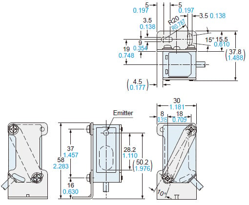
Dimensions
- Unit: mm in
HG-C□L3-P(-J)
Sensor
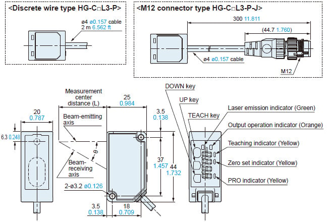
| Model No. | Measurement center distance (L) | θ |
|---|---|---|
| HG-C1030L3-P(-J) | 30 1.181 | 30° |
| HG-C1050L3-P(-J) | 50 1.969 | 22.5° |
| HG-C1100L3-P(-J) | 100 3.937 | 12.5° |
| HG-C1200L3-P(-J) | 200 7.874 | 6.3° |
| HG-C1400L3-P(-J) | 400 15.748 | 3.2° |
MS-HG-01
Simple mounting bracket (Optional)
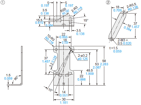
Material: Stainless steel (SUS304)Two M3 (length 25 mm0.984 in) screws with washers [cold rolled carbon steel (SPCC)] are attached.
Assembly dimensions
------------------------------ Tab7 showing ------------------------------
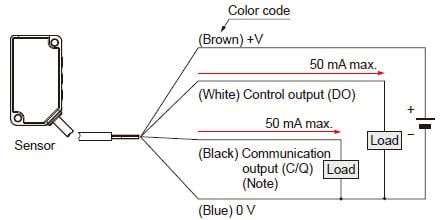
I/O Circuit and Wiring diagrams
WIRING DIAGRAMS
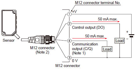
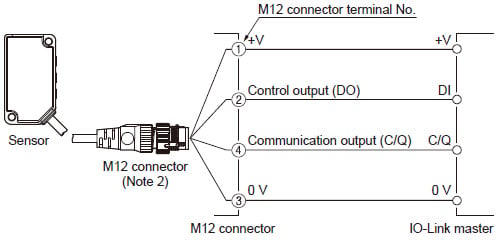
HG-C□L3-P
IO-Link compatible, Self-monitoring, Discrete wire type
<When using as an ordinary sensor>
<When connecting to the IO-Link master>
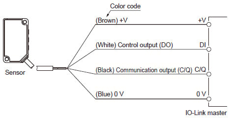
Note: When the sensor is used as an ordinary sensor, the communication output (C/Q) provides the same output operation as the control output (DO).
HG-C□L3-P-J
IO-Link compatible, Self-monitoring, M12 connector type
<When using as an ordinary sensor>
<When connecting to the IO-Link master>
Notes: 1)
When the sensor is used as an ordinary sensor, the communication output (C/Q) provides the same output operation as the control output (DO).
2)
When wiring with the discrete wire or extending the cable from the M12 connector, separately prepare commercially available M12 connector cable.
M12 connector terminal arrangement diagram
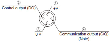
Note: When the sensor is used as an ordinary sensor, the communication output (C/Q) provides the same output operation as the control output (DO).
| Terminal No. | Designation |
|---|---|
| ① | +V |
| ② | Control output (DO) |
| ③ | 0V |
| ④ | Communication output (C/Q) (Note) |
------------------------------ Tab8 showing ------------------------------
- Never use this product as a sensing device for personnel protection.
- In case of using sensing devices for personnel protection, use products which meet laws and standards, such as OSHA, ANSI or IEC etc., for personnel protection applicable in each region or country.
- Do not operate products using methods other than the ones described in the instruction manual included with each product. Control or adjustment through procedures other than the ones specified may cause hazardous laser radiation exposure.

*This product complies with the FDA regulations (FDA 21 CFR 1040.10 and 1040.11) in accordance with FDA Laser Notice No. 56, except for complying with IEC 60825-1 Ed. 3.
Safety standards for laser beam products
For the purpose of preventing any injury which may occur to the user by the use of the laser product in advance, the following standards have been established by the IEC Standards, EN Standards, JIS Standards, GB Standards, KS Standards and FDA Regulations.
IEC : IEC 60825-1:2014
EN : EN 60825-1:2014/A11:2021
JIS : JIS C 6802:2014
GB : GB 7247.1-2012
KS : KS C IEC 60825-1:2014
FDA : PART 1040.10, 1040.11(Laser Notice No.56 applied)
These standards classifies laser products according to the level of hazard and provide the safety measures for respective classes. Based on the above standards, HG-C series is classified as a Class 2 laser product.
Explanation of hazard levels| Classification | Summary of hazard evaluation |
|---|---|
| Class 2 | A laser that emits visible light with the wavelength range of 400 nm to 700 nm under which eyes can be protected by an aversive reaction (Avoidance behavior) such as a blink. |
Note: When an unexpected failure occurs, dangerous radiation may be generated. Therefore, pay special attention to safety.
Safe use of laser products
- For the purpose of preventing users from suffering injuries by laser products, each standard stipulates (Safety of laser products). Kindly check the standards before use.
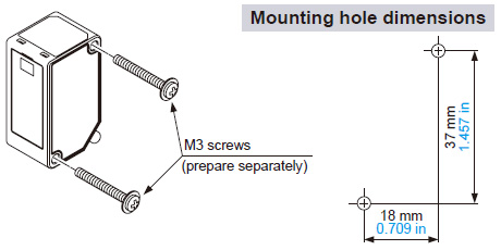
Mounting
- When mounting this product, use M3 screws.
The tightening torque should be 0.5 N·m.
Please prepare M3 screws separately.
- When mounting the simple mounting bracket (optional) on this product, the tightening torque should be 0.5 N·m or less.
Note:Due to the simple mounting bracket, the sensing characteristics may not be hold depending on the installation condition, in case of the purposes for acquiring the displacement data and a fine detecting.
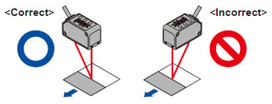
Mounting direction
• Direction to a movable body
<When there are differences in material and color>
- When performing measurements of moving objects with excessively different materials and colors, mount the product per the following directions to minimize measurement errors.
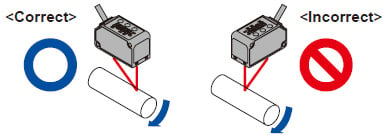
<Measurement of rotating objects>
- When measuring rotating objects, mount the product as follows.
Measurement can be performed with minimized effect on the object caused by up / down deflection, position deviation and etc.
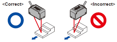
<When there is a step>
- When there is a step in the moving object, mount the product as follows.
Measurement can be performed with minimized effect from the edges of the steps.
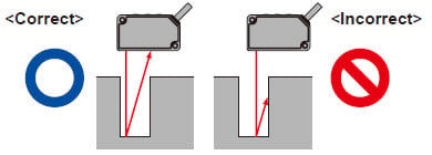
•Measuring of narrow locations and recesses
- When measuring in narrow locations or inside holes, mount the product so that optical path from the lightemitting part to light-receiving part is not interrupted.
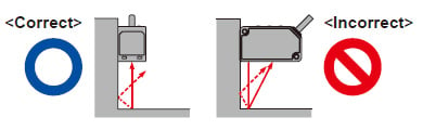
•When mounting the product on a wall
- Mount the product as follows, so that the multiple light reflections on the wall do not emit to the light-receiving part. When the reflection factor on a wall is high, it is effective to use a dull black color.
Others
- This product has been developed / produced for industrial use only.
- Make sure that the power supply is OFF before starting the wiring.
- If the wiring is performed incorrectly, it will cause a failure.
- Do not run the wires together with high-voltage lines or power lines, or put them in the same raceway. This can cause malfunction due to induction.
- Verify that the supply voltage variation is within the rating.
- If power is supplied from a commercial switching regulator, ensure that the frame ground (F.G.) terminal of the power supply is connected to an actual ground.
- If noise generating devices (switching regulators, inverter motors, etc.) are used around the sensor mounting area, make sure to connect the frame ground (FG) terminal of the device.
- Do not use this product during the transient state when the power supply is turned ON.
- The overall length of the cable can be extended to 10 m 32.808 ft maximum (HG-C1000L series: 20 m 65.617 ft maximum) with a cable size of 0.3 mm2 or more.
- Make sure that stress by forcible bend or pulling is not applied to the sensor cable joint.
- Although it depends on the type, light from rapid start type or high frequency lighting type fluorescent lights, sunlight and etc. may affect the sensing, therefore make sure to prevent direct incident light.
- This product is suitable for indoor use only.
- Keep water, oil, fingerprints and etc. which reflect light, or dust, particles or etc. which interrupts the light, away from the emitting / receiving surfaces of this product.
If contaminants adhere to the surface, wipe off with a dust-free soft cloth, or lens cleaning paper. - Do not use the sensor in locations where there is excessive vapor, dust or etc. or in an atmosphere where corrosive gases, etc. is generated.
- Take care that the product does not come in contact with oil, grease, organic solvents such as thinner, etc., strong acid or alkaline.
- Make sure to turn OFF the power supply, before cleaning the light emitting / receiving windows of the sensor head.
- There is a certain deviation in the directionality of this product. Install the product using a mounting bracket or similar fitting to allow the adjustment of optical axis.
- The internal memory (nonvolatile) of this product has a service life. Settings cannot be configured more than 100,000 times.