


Basic Information

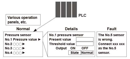
Capable of diagnosing own state and reporting to the host device

HG-C1000L

SC-LG2-CEF-P
Features
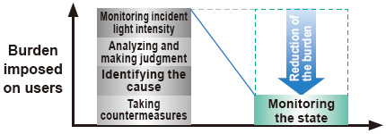
Reduction of the data analysis burdenone small step towards IoT.
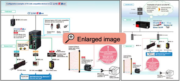
IO-Link compatible Collecting sensor level data
Field data collected and accumulated for “preventive maintenance” and “operation monitoring”.
An analysis of such field data requires high-level know-how and time, causing a burden to people responsible for the production site management.
The Self-Monitoring Sensor manufactured by Panasonic is capable of reporting sensor data and its own state to the host device through the I/O Link master.
With the Self-Monitoring Sensor, you can immediately judge the state of the sensor and easily identify the cause of failure. Thus, this sensor contributes to the reduction of the burden experienced by the client in collecting and analyzing data.
Incorporated self-monitoring function
With the Panasonic's Self-Monitoring Sensor,you can get high-level solutions!
Problems are solved by the Self-monitoring function.
| Status | Judgement of the state | ||
|---|---|---|---|
| Normal | Operation is normal. | ||
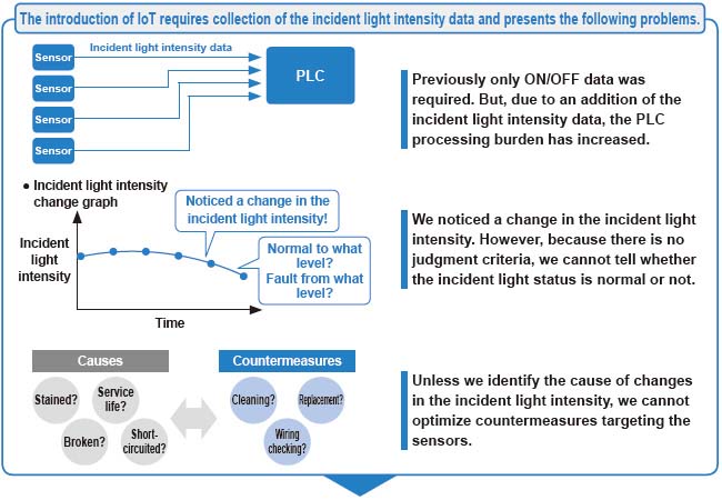
| Notification | Check the settings. Detected state is faulty. | * Recover to the normal state through checking installation and settings. Reduction in the incident light intensity | |
| Caution | Getting close to the end of service life. Reached the state where the device should be replaced. | * Limitation in the writing frequency into the memory or in the operation hours, etc. | |
| Fault | Short-circuited or broken. Reached the state where it is impossible to control as a device. | * Short-circuited output, damaged EEPROM, etc. | |
*
By creating a program with a PLC, etc., the "State" of the self-monitoring sensor can be grasped.
Software are available for download. *Membership registration is required to access/download this data.
>>Go to Data download.
Easy use of IoT
“Predictive maintenance” can be easily achieved through monitoring the state of the Self-Monitoring Sensor.
VERSION UP 1
"Superior visibility": Improved visibility in Digital Display
Improvements to the digital display deliver a wide viewing angle along with increased clarity. The display pressure range and set pressure range have also been increased.

VERSION UP 2
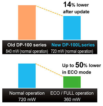
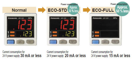
"Reduced environmental impact": 14% lower power consumption (during normal operation)
Thanks to a redesign of its circuitry, power consumption of the low-power-consumption DP-100L series during normal operation has been reduced by 14%.
The display is shut off entirely during ECO / FULL mode operation for power savings of up to 50% compared to normal operation, and display brightness is lowered during ECO / STD mode operation for power savings of up to 30% compared to normal operation.
VERSION UP 3
Enhanced power circuitry Addition of a reverse polarity protection circuit to the transistor output circuit
To prevent from breakage due to miswiring.
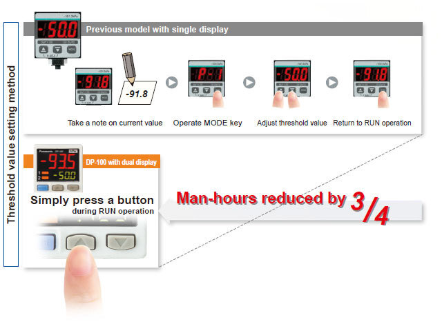
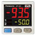
"Current value" and "threshold value" can be checked at the same time! Dual display allows direct setting of threshold value
Equipped with a 30 mm 1.181 in square compact-sized dual display.
The current value and the threshold value can be checked at the same time, so the threshold value can be set and checked smoothly without switching to another screen mode.
ON / OFF operations still continue while the threshold values are being set, so setting to the same sensitivity as dial control-type sensors is possible.
Key lock function is equipped as well.
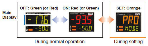
3-color display (Red, Green, Orange)
The main display changes color in line with changes in the status of output ON / OFF operation, and it also changes color while setting is in progress. The sensor status can therefore be understood easily, and operating errors can be reduced.
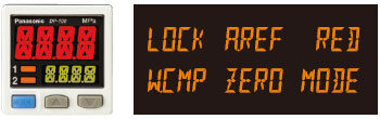
Readable digital display
12 segments are used and an alphanumeric display has been adopted. This improves visual checking of letters and numbers.
All models in the line-up are compound pressure types
No sensor settings are required to switch between positive pressure and negative pressure, so that the number of registered part numbers can be decreased.
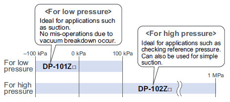
High performance accomplished [Low pressure type]
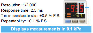
The low pressure type displays measurements in 0.1 kPa at a resolution of 1/2,000 and has a response time of 2.5 ms (variable up to 5,000 ms), ±0.5 % F.S. temperature characteristics and ±0.1 % F.S. repeatability, giving it high performance.
The sensor’s setting operation mode has a 3-level configuration to suit the frequency of use.
The setting levels are clearly separated into "RUN mode" for operation settings that are carried out daily, "MENU SETTING mode" for basic settings, and "PRO mode" for special and detailed setting.
These make setting operations easy to understand and easy to carry out.
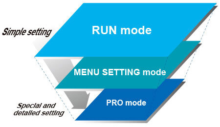
RUN mode
Settings such as threshold value adjustment and key lock operation can be carried out while the sensor is operating.
MENU SETTING mode
Basic settings such as output mode setting and NO / NC switching can be carried out.
PRO mode
High-level function settings such as hysteresis adjustment and the copy function can be carried out.
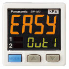
1. EASY mode
This mode is used for comparative output ON / OFF control.
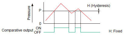
Notes: Hysteresis can be fixed to one of eight different levels.
2. Hysteresis mode
This mode is used for setting comparative output hysteresis to the desired level and for carrying out ON / OFF control.
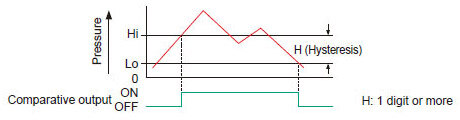
Notes: "Hi-1" or "Lo-1" appears in the sub display for comparative output 1, and "Hi-2" or "Lo-2" appears for comparative output 2.
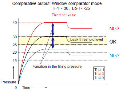
3. Window comparator mode
This mode is used for setting comparative output ON and OFF at pressures within the setting range.
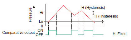
Notes: Hysteresis can be fixed to one of eight different levels.
Equipped with auto-reference / remote zero-adjustment functions, More precise pressure
management is achieved with a minimum of effort [Multi-function type]
If the reference pressure of the device changes, two functions are selectable. One is auto-reference function, which partially shift the comparative output judgment level by the amount that the reference pressure shifts. The other is remote zero-adjustment function, which can reset the display value to zero via external input. These functions are ideal for places where the reference pressure fluctuates wildly, or where fine settings are required.
Without auto-reference and remote zero-adjustment functions
Because the threshold level is fixed for conventional pressure sensors, changes in the reference pressure result in wrong decisions.
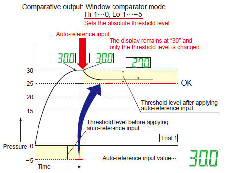
With auto-reference function applied
When auto-reference input is applied, the reference pressure "30" is added to the threshold level. If the reference pressure changes to "20" or "40", the auto-reference input compensates for this every time by changing the threshold level, so any variation in the filling pressure can be ignored.
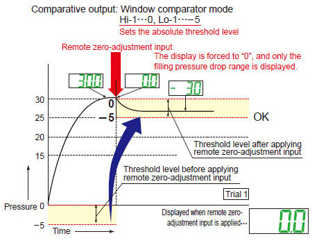
With remote zero-adjustment function applied
When remote zero-adjustment input is applied, the reference pressure is forced to "0". If the reference pressure changes to "20" or "40", the remote zero-adjustment input adjusts the reference pressure to "0" every time the reference pressure changes, so any variation in the filling pressure can be ignored.
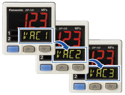
Sub display can be customized
The sub display can be set to indicate any other desired values or letters apart from the threshold value. This eliminates the need for tasks such as affixing a label to the device to indicate the normal pressure value.
Setting details can be recognized at a glance
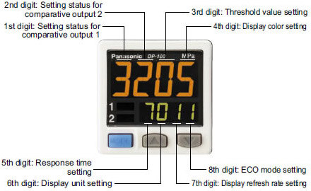
The DP-100L setting details appear in the digital display. Because the settings are in numeric form that can be easily understood, it is useful such as when receiving technical support by telephone.
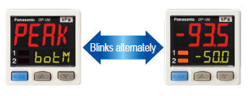
Peak hold and Bottom hold functions
The peak values and bottom values for fluctuating pressures can be displayed using the dual display.
Energy-saving design! Equipped with an ECO mode
This mode lowers the display luminance to cut power consumption by approximately 30 %. The displays can also be turned off completely to achieve a power saving of approximately 50 %.
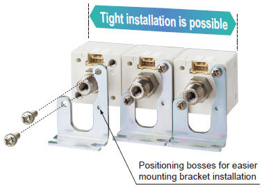
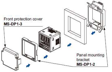
Tight installation to panels is possible
An exclusive mounting bracket that is suitable for 1 to 6 mm 0.039 to 0.236 in panel thickness is available.
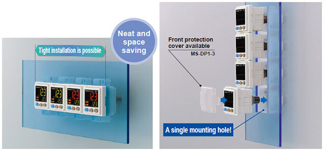
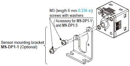
An exclusive mounting bracket that supports tight installation is available
Space savings can also be achieved even when an L-shaped mounting bracket is used.
・MS-DP1-1
・MS-DP1-5
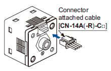
Cable can be connected with one-touch
Connector attached cable (2m 6.562 ft), as an accessory, can be connected easily with one-touch connection.
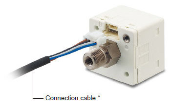
* Options: 1 m3.281 ft/ 3m9.843 ft/ 5m16.404 fttypes are also available.
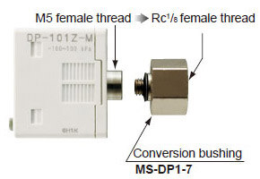
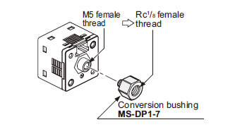
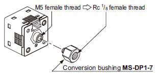
Rc1/8 conversion bushing is available. Compatible with conventional model <br>[For short pressure port type]
By equipping the push-in converter with DP-10□-M(-P), pressure port can be converted from M5 female thread to Rc1/8 female thread. Bore diameter conversion to the DP2 / DP3 series is possible.
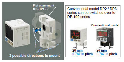
Flat installation on the wall by shifting the direction of the pressure port
[For short pressure port type]
By mounting the flat attachment to DP-10□-M(-P), pressure port and cable can now be pulled out in downward, left or right directions. Flat mounting on surfaces such as the wall is made possible.
| Model No. | Pressure port |
|---|---|
| MS-DP1-FM | M5 female thread |
| MS-DP1-FR | Rc1/8 female thread |
| MS-DP1-FN | NPT1/8 female thread |
| MS-DP1-FE | G1/8 female thread |
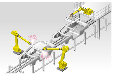
Applications
IoT Examples at FA Sites
Before the introduction of Self-Monitoring Sensors
Preventive maintenance
●We want to avoid production line stoppage that might occur due to unexpected sensor failure.
Line stoppage hours × (manufacturing unit cost / hour) = Loss
●We want to minimize the production line down time to almost zero.
Problems
◆The amount of data to be collected is large and this may lower the PLC processing capacity.
◆The burden of data analysis is large.
◆Resetting the replaced sensors is troublesome.

After the introduction of Self‑Monitoring Sensors
From preventive maintenance to predictive maintenance
Leave the sensor diagnosis to the sensor itself.
●All you need to do is to monitor the sensor state.
●PLC can be used exclusively for controlling devices.
●Possible to check detail information at a desired timing.
Leave the resetting for replaced sensors to the higher-level master
●Automatically written from the connected master.
●Possible not only to save time but also to prevent human errors.
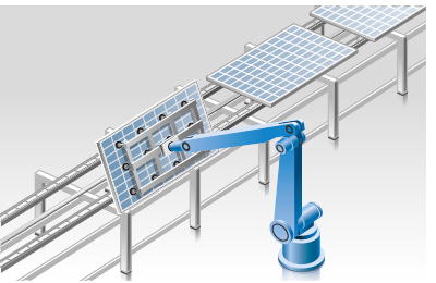
IoT Examples at FA Sites 02
Before the introduction of Self-Monitoring Sensors
Remote controlling and batch settings
●We want to place sensors close to sensing points as much as possible.
However, it is often difficult to make settings, particularly when there are many sensors to install.
●We want to send predetermined parameter values in a batch file for a repeater, etc.
●We want to confirm that required sensors are properly connected at the startup of the system.

Problems
◆It takes time to set sensors.
◆We want to avoid mistakes in setting sensors or wiring.


After the introduction of Self‑Monitoring Sensors
Fully utilize the advantages of the IO‑Link output.
●Possible to read or write set values through external
interface.
●Possible to set multiple sensors in a batch process.
●Possible to save the set parameters in an external medium.
●Possible to recognize and discriminate individual information.
Order guide
Model No.
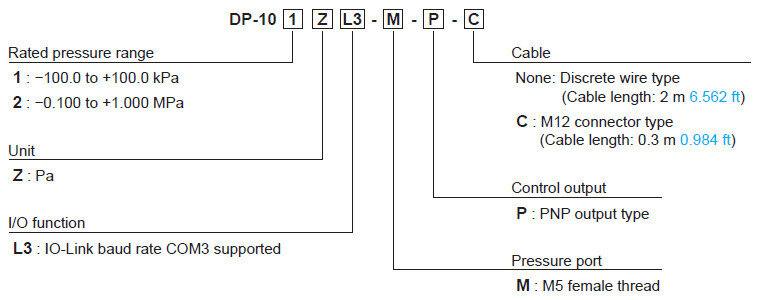
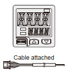
Discrete wire type
| Type | Appearance | Rated pressure range | Model No. | Pressure port | Control output |
|---|---|---|---|---|---|
| For low pressure |
| -100.0~ +100.0kPa | DP-101ZL3-M-P | M5 female thread | PNP open-collector transistor |
| For high pressure | -0.100~ +1.000MPa | DP-102ZL3-M-P |
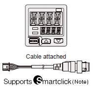
M12 connector type
| Type | Appearance | Rated pressure range | Model No. | Pressure port | Control output |
|---|---|---|---|---|---|
| For low pressure |
| -100.0~ +100.0kPa | DP-101ZL3-M-P-C | M5 female thread | PNP open-collector transistor |
| For high pressure | -0.100~ +1.000MPa | DP-102ZL3-M-P-C |
Note:
Smartclick is a registered trademark of OMRON Corporation.
Accessory
• CN-14A-C2 (Connector attached cable 2 m 6.562 ft)
* M12 connector cable (0.3 m0.984 ft) is not sold separately.
Option
| Designation | Model No. | Description | |
|---|---|---|---|
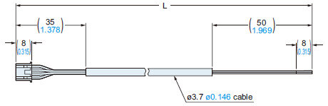
| Connector attached cable | CN-14A-C1 | Length: 1 m 3.281 ft | Discrete wires 0.2 mm2 4-core cabtyre cable with connector on one end Cable outer diameter: ø3.7 mm ø0.146 in |
| CN-14A-C2(Note) | Length: 2 m 6.562 ft | ||
| CN-14A-C3 | Length: 3 m 9.843 ft | ||
| CN-14A-C5 | Length: 5 m 16.404 ft | ||
| Connector attached cable (Bendingresistant cable) | CN-14A-R-C1 | Length: 1 m 3.281 ft | Discrete wires 0.2 mm2 4-core bending-resistant cabtyre cable with connector on one end Cable outer diameter: ø3.7 mm ø0.146 in |
| CN-14A-R-C2 | Length: 2 m 6.562 ft | ||
| CN-14A-R-C3 | Length: 3 m 9.843 ft | ||
| CN-14A-R-C5 | Length: 5 m 16.404 ft | ||
| Connector | CN-14A | Set of 10 housings and 40 contacts | |
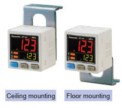
| Sensor mounting bracket | MS-DP1-1 | Allows sensors to be installed on the flooring or ceiling. Multiple sensors can also be mounted closely. | |
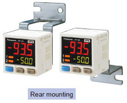
| MS-DP1-5 | Allows sensors to be installed on the wall. Multiple sensors can also be mounted closely. | ||
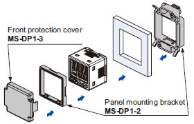
| Panel mounting bracket | MS-DP1-2 | Allows installation to panels with thickness of 1 to 6 mm 0.039 to 0.236 in. Multiple sensors can also be mounted closely. | |
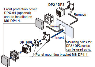
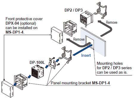
| MS-DP1-4 | Allows replacement from DP2 / DP3 series to DP-100L series. For newly designed set-up, please use panel mounting bracket MS-DP1-2 for panel mounting. | ||
| Front protection cover | MS-DP1-3 | Protects the adjustment surfaces of sensors. (Can be attached when using the panel mounting bracket MS-DP1-2) | |
| DPX-04 | Protects the adjustment surfaces of sensors. (Can be attached when using the panel mounting bracket MS-DP1-4) | ||
| Conversion bushing | MS-DP1-7 | By equipping with the sensor, pressure port can be converted to Rc1/8 female thread. Replacement from DP2 / DP3 series is possible. | |
| Flat attachment | MS-DP1-FM | M5 female thread | Pressure port and cable can now be pulled out in downward, left or right directions. Flat mounting on surfaces such as the wall is made possible. |
| MS-DP1-FR | Rc1/8 female thread | ||
| MS-DP1-FN | NPT1/8 female thread | ||
| MS-DP1-FE | G1/8 female thread | ||
Note:The connector attached cable CN-14A-C2 is supplied with DP-10□ZL3-M-P.
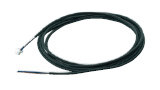
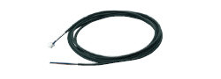
Connector attached cable
•CN-14A-C□ •CN-14A-R-C□
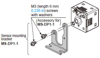
Sensor mounting bracket
· MS-DP1-1
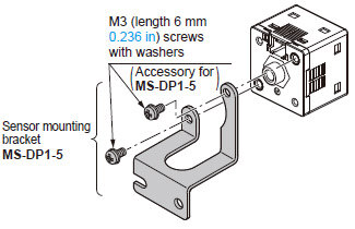
· MS-DP1-5
Panel mounting bracket, Front protection cover
· MS-DP1-2
· MS-DP1-3
· MS-DP1-4
Conversion bushing
· MS-DP1-7
Flat attachment
· MS-DP1-FM
Net weight: MS-DP1-FM 15g approx.MS-DP1-FR/FN/FE 25g approx.Two M3 (length 8 mm0.315 in) screws, twoM4 (length 20 mm0.787 in) screws are attached.
· MS-DP1-FR
· MS-DP1-FN
· MS-DP1-FE
Net weight: MS-DP1-FM 25g approx.MS-DP1-FR/FN/FE 25g approx.Two M3 (length 8 mm0.315 in) screws, twoM4 (length 20 mm0.787 in) screws are attached.
Recommended connector*
Manufactured by J.S.T. Mfg. Co.,Ltd.
Contact: SPHD-001T-P0.5
Housing: PAP-04V-S
Recommended crimping tool*
Manufactured by J.S.T. Mfg. Co.,Ltd.
Model No.: YC-610R
Recommended e-CON connector
Manufactured by 3M Japan Limited
Adapted connector : 37104-3122-000 FL
Please refer to "Introducing the 3M™ mini-clamp connector" for details.
Recommended extension cables for M12 connector type
Manufactured by OMRON Corporation
Extension cable with connectors on both ends XS5W series
![]()
*Smartclick is a trademark or registered trademark of OMRON Corporation.
Dimensions
- Unit: mm in
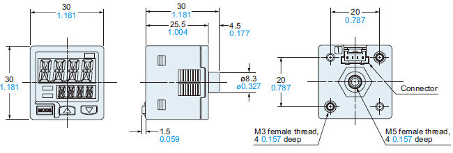
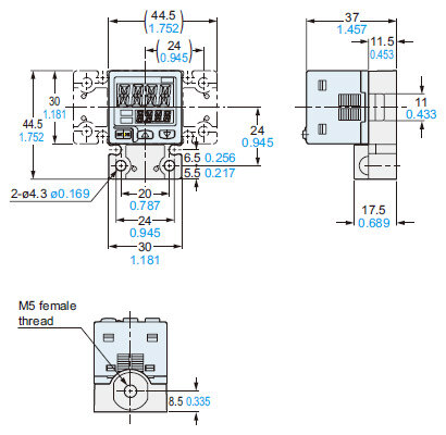
DP-10□ZL3-M-P(-C)
Sensor
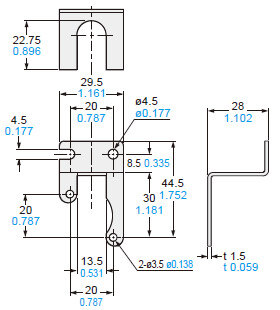
MS-DP1-1
Sensor mounting bracket (Optional)
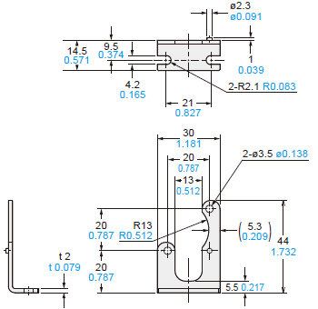
Material : Cold rolled carbon steel (SPCC) (Trivalent uni-chrome plated)Two M3 (length 6 mm0.236 in) screws with washers are attached.
Assembly dimensions
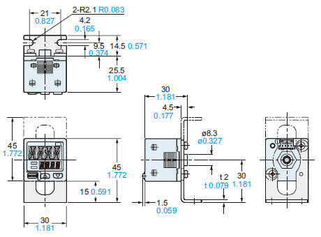
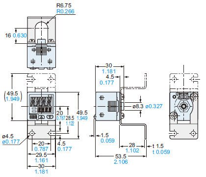
MS-DP1-5
Sensor mounting bracket (Optional)
Material: Stainless steel (SUS304)Two M3 (length 6 mm0.236 in) screws with washers are attached.
Assembly dimensions
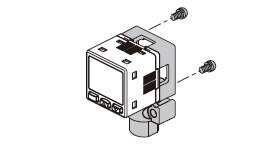
MS-DP1-2
MS-DP1-3
Panel mounting bracket (Optional), Front protection cover (Optional)
Assembly dimensions
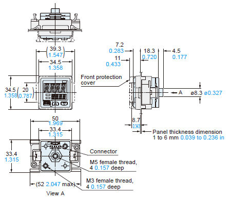
Material: Polyacetal (Panel mounting bracket)Polycarbonate (Front protection cover)
Panel cut-out dimensions
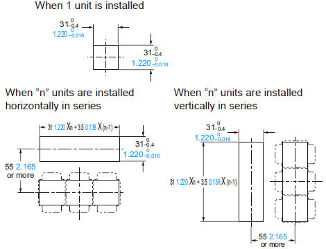
Note:The panel thickness should be 1 to 6 mm0.039 to 0.236 in.
MS-DP1-4
Panel mounting bracket (Optional)
Assembly dimensions
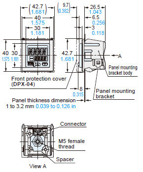
Material:Nylon 6 (Panel mounting bracket body)Stainless steel (SUS304)(Panel mounting bracket)Cold rolled carbon steel (SPCC)(Trivalent uni-chrome plated) (Spacer)
Panel cut-out dimensions
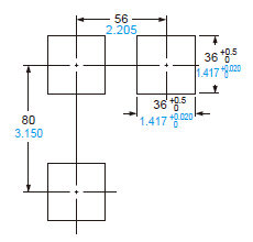
Note:The panel thickness should be 1 to 3.2 mm0.039 to 0.126 in.
MS-DP1-7
Conversion bushing (Optional)
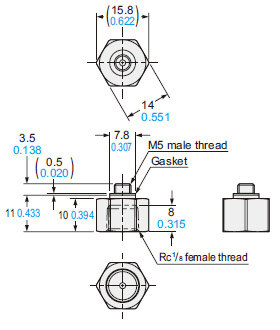
Material: Brass (Nickel plated)Weight: 10 g approx.
MS-DP1-FM
Flat attachment (Optional)
Assembly dimensions
Material:
Polybutylene terephthalate (PBT)
(Glass fiber reinforced) (Enclosure)
Stainless steel (SUS303) (Pressure port)
Hydrogenated Nitrile Butadiene Rubber
(H-NBR) (O-ring)
Weight :
15 g approx. (flat attachment only)
Two M3 (length 8 mm 0.315 in) screws, two M4 (length 20 mm 0.787 in) screws are attached.
MS-DP1-FR/FN/FE
Flat attachment (Optional)
Assembly dimensions

Material:Polybutylene terephthalate (PBT)(Glass fiber reinforced) (Enclosure)Stainless steel (SUS303) (Pressure port)Hydrogenated Nitrile Butadiene Rubber(H-NBR) (O-ring)Weight :25 g approx. (flat attachment only)
Two M3 (length 8 mm 0.315 in) screws, two M4 (length 20 mm 0.787 in) screws are attached.
CN-14A(-R)-C□
Connector attached cable (Optional, CN-14A-C2 is attached to DP-10□ZL3-M-P)
•Length L
| Model No. | Length L (mm in) |
|---|---|
| CN-14A(-R)-C1 | 1,000 39.370 |
| CN-14A(-R)-C2 | 2,000 78.740 |
| CN-14A(-R)-C3 | 3,000 118.110 |
| CN-14A(-R)-C5 | 5,000 196.850 |
Dedicated M12 connector cable (attached to DP-10□ZL3-M-P-C)
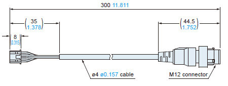
Note: Be sure to use the dedicated M12 connector cable attached to the product. Note that the pin arrangement is different from that for commercially available M12 connector cables.
I/O Circuit and Wiring diagrams
Terminal arrangement diagram of the connector on the sensor side
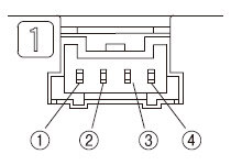
| Terminal No. | Designation |
|---|---|
| ① | +V |
| ② | Communication output (C/Q) (Note) |
| ③ | Control output (DO) |
| ④ | 0V |
Note:
When the sensor is used as an ordinary sensor, the communication output (C/Q) provides the same output operation as the control output (DO).
WIRING DIAGRAMS
DP-10□ZL3-M-P
Discrete wire type
<When using as an ordinary sensor>
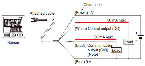
<When connecting to the IO-Link master>
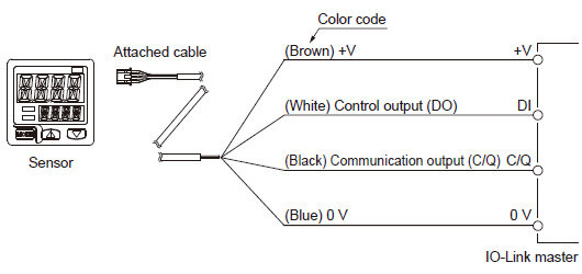
Note:
When the sensor is used as an ordinary sensor, the communication output (C/Q) provides the same output operation as the control output (DO).
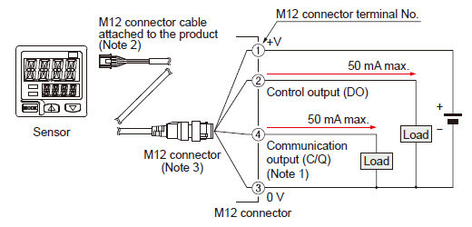
DP-10□ZL3-M-P-C
M12M12 connector type
<When using as an ordinary sensor>
<When connecting to the IO-Link master>
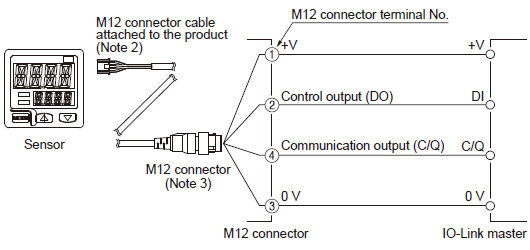
Notes: 1)
When the sensor is used as an ordinary sensor, the communication output (C/Q) provides the same output operation as the control output (DO).
2)
Be sure to use the dedicated M12 connector cable attached to the product. Note that the pin arrangement is different from that for commercially available M12 connector cables.
3)
When wiring with the discrete wire or extending the cable from the dedicated M12 connector attached to the product, separately prepare commercially available M12 connector cable.
M12 connector terminal arrangement diagram
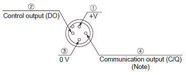
| Terminal No. | Designation |
|---|---|
| ① | +V |
| ② | Control output (DO) |
| ③ | 0V |
| ④ | Communication output (C/Q) (Note) |
Note:
When the sensor is used as an ordinary sensor, the communication output (C/Q) provides the same output operation as the control output (DO).
Wiring
- Make sure that the power supply is off while wiring.
- Verify that the supply voltage variation is within the rating.
- If power is supplied from a commercial switching regulator, ensure that the frame ground (F.G.) terminal of the power supply is connected to an actual ground.
- In case noise generating equipment (switching regulator, inverter motor, etc.) is used in the vicinity of this sensor, connect the frame ground (F.G.) terminal of the equipment to an actual ground.
- Do not run the wires together with high-voltage lines or power lines or put them in the same raceway. This can cause malfunction due to induction.
- Incorrect wiring will cause problems with operation.
Connection
- Do not apply stress directly to the connection cable leader or to the connector.
Mounting
- MS-DP1-1 / MS-DP1-5 sensor mounting brackets are available separately, and it should be used for mounting.
When tightening the sensor to the sensor mounting bracket, use a tightening torque of 0.5 N·m or less.
- The MS-DP1-2 panel mounting bracket (optional) and the MS-DP1-3 front protection cover (optional) are also available.
- The MS-DP1-4 panel mounting bracket is available when switching from the DP2 / DP3 series.
- The MS-DP1-7 conversion bushing is available. It can be used to switch between this model and the DP2 / DP3 series.
When connecting to the pressure port, use a tightening torque of 1.0 N·m or less.
(1)Decide the direction of this product to mount with the sensor.
- The MS-DP1-F□ flat attachment is available. If using the MS-DP1-F□ flat attachment (optional), install by following the procedures given below.
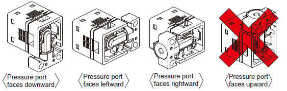
Note:It is not possible to mount this product such that the pressure port faces upward.
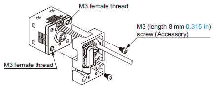
(2)Mount this product with the M3 female threads of the sensor by using the attached M3 (length 8 mm 0.315 in) screws. The tightening torque should be 0.5 N·m or less.
(3)Mount this product with the mounting surface by using the attached M4 (length 20 mm 0.787 in) screws. The tightening torque should be 1.2 N·m or less.
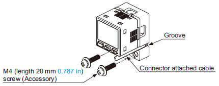
Note: Take care that if the cable with connector is sticking out of the side groove of this product when mounting, the cable may disconnected.
Piping
- If connecting a commercially-available joint to the pressure port of the sensor, hold the main unit in your hand to steady it, and tighten to a torque of 1 N·m or less.
If it is tightened to an excessive torque, the joint or the main unit may become damaged. - If connecting a commercially-available joint to the pressure port of the MS-DP1-7 conversion bushing, tighten to a torque of 9.8 N·m or less.
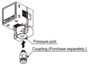
- The tightening torque should be 1 N·m or less when connecting a coupling to the pressure port of MS‑DP1‑FM flat attachment.
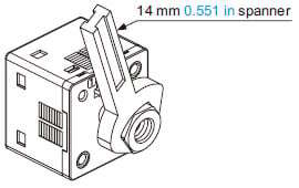
- When connecting the coupling to the pressure port of MS‑DP1‑FR/FE/FN flat attachment, hold the pressure port with a 14 mm 0.551 in spanner and make sure that the tightening torque is 9.8 N·m or less.
In addition, in order to prevent any leakage, wind a sealing tape on the coupling when connecting.
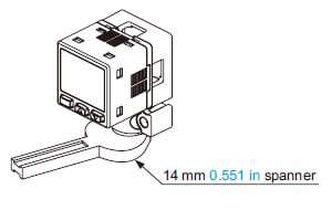
Note: Do not tighten the pressure port by holding the product with the spanner.It may cause the product breakage.
Flat attachment MS-DP1-F□
- Make sure to mount MS-DP1-F□ with the sensor properly.
If it is not mounted properly, air leakage may occur. - Take care that the excessive mounting and dismounting of this product may cause deterioration of the O-ring.
- If you touch the O-ring of MS-DP1-F□, or any scratch or dust, etc. is attached to it, air leakage may occur and the sensing performance may deteriorate.
Take sufficient care when using and storing MS-DP1-F□.
Others
- This product has been developed / produced for industrial use only.
- Use within the rated pressure range.
- Do not apply pressure exceeding the pressure withstandability value. The diaphragm will get damaged and correct operation shall not be maintained.
- Do not use during the initial transient time (0.5 sec. approx.) after the power supply is switched on.
- This product is suitable for indoor use only.
- The specification may not be satisfied in a strong magnetic field.
- Avoid dust, dirt, and steam.
- Take care that the sensor does not come in direct contact with water, oil, grease, or organic solvents, such as, thinner, etc.
- Do not insert wires, etc., into the pressure port.
The diaphragm will get damaged and correct operation shall not be maintained. - Do not operate the keys with pointed or sharp objects.