Basic Information
New Concept
Both Compact and Robust


UL, CSA : Certified by TÜV SÜD America Inc.
GB : Conforming to GB/T 4584
Korean KCs Mark : Excluding SF4D-□-01


Features
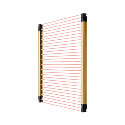
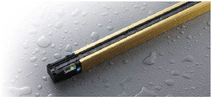
Slim and robust unit body resists twisting, warping and impact
Downsized internal unit, increased case thickness
The internal unit was redesigned and downsized extensively.
The internal unit was downsized to less than 40% (volume ratio) as compared to the conventional model while achieving higher performance.
The case structure was also optimized and offers high rigidity without any change in external dimensions.
The SF4D series provides high performance and high reliability while maintaining the installation and wiring compatibility with the previous models.
![小型・堅牢 セーフティライトカーテン[Type4 PLe SIL3] SF4D](https://ap.industry.panasonic.com/hubfs/pid-corp/products/fasys/sensor/safety/sf4d/images/pic02.jpg)
Mounting brackets feature both rigidity and ease of handling
Completely new mounting brackets and structure. In addition to strengthening the rigidity of the mounting brackets, we have also improved the method of attachment to the safety light curtain unit
to significantly increase the mount strength. The dead zoneless mounting bracket and the optional mounting bracket* that does not extend from aluminum frame are also available for easier use.
*in case of rear mounting
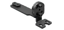
Beam adjustment
mounting bracket
M5×2 tightening type: MS-SFD-1-5
M6×1 tightening type: MS-SFD-1-6
M8×1 tightening type: MS-SFD-1-8

mounting bracket
MS-SFD-3-6

mounting bracket
MS-SFD-4BG
Conventional model

When the unit was subjected to intense shock, a large load was occasionally placed on the aluminum case joint.

This reduces the load on the top case and bottom case, and helps prevent beam misalignment and failure due to shock.
New high power optical system offering stable operation even for long distance setup
Increased power of emitter element
The power of the emitter has been increased significantly. The high resistance to dust and dirt contributes to the reduction of maintenance frequency.

Minimization of deviations among elements
We incorporated the element alignment technology that we cultivated for fiber sensors in the safety light curtain. This minimizes curves due to emitter and receiver mounting deviations and quality deviations due to differences in individual elements.
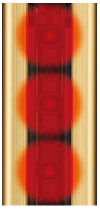
Redesigned emitter element layout and structure
The scattering light energy from each emitter element is guided efficiently through the lens. The light energy of the emitter element is utilized fully, and the light distribution characteristics were optimized for the specific aperture angle.*
![小型・堅牢 セーフティライトカーテン[Type4 PLe SIL3] SF4D](https://ap.industry.panasonic.com/hubfs/pid-corp/products/fasys/sensor/safety/sf4d/images/pic10.jpg)
* The aperture angle of a Type 4 safety light curtain is specified as a maximum of 2.5° each on the right and left at a detection distance of 3 m 9.843 ft or more.
Shuts out liquids and dust IP67, IP65 (IEC) NEMA Type 13 (NEMA 250)
The SF4D series complies with IP67 and IP65 (IEC) as well as NEMA Type 13 (NEMA 250)*1.
The unit structure prevents the entry of not only water but also coolant and other liquids*2 to protect the internal unit.
*1
The SF4D series complies with the Type 13 requirements for non-explosion-proof enclosures specified in NEMA 250, "Enclosure for Electrical Equipment (1,000 V Maximum)," established by NEMA (National Electrical Manufacturers Association) in the United States.
Type 13: Enclosures for mainly indoor use which satisfy the following conditions:
・Prevention of incidental contact with the enclosed equipment
・Protection against falling dirt and protection against circulating airborne particles
・Protection against spraying, splashing and seepage of water and noncorrosive lubricants
*2
If used in a place where cutting fluid can splash, additives in the fluid may cause degradation. Please check in advance whether the SF4D series is resistant to the specific cutting fluid used by your company.
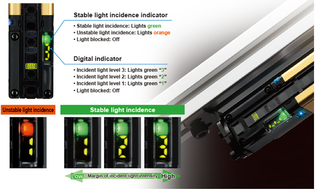
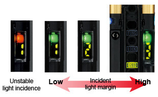
Digital indicator with a numeric display of light incidence margin facilitates beam axis adjustment and preventive maintenance.
The light incidence margin is indicated by the “stable light incidence indicator” and “digital indicator”. This function enables appropriate beam adjustment and work quality control during installation of the device. The indicators also show whether there is dirt on the detection surface or beam misalignment due to play.
This enables the numeric display to be used for startup inspection and preventative maintenance.
* When optical synchronization is set, only the indicator on the receiver lights up.
Other features!
Well-thought-out indicators
The indicators show stable light incidence status and notify various conditions. The OSSD indicator, interlock indicator and function setting indicator are arranged between the beam axes for easy visibility.
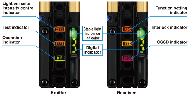
Light incidence intensity indication
The indicator shows the light incidence margin with a numeric display (1 to 3).
The displayed number decreases when there is dirt on the detection surface or beam axis misalignment occurs due to a loose mounting condition. This provides useful information during pre-operation inspection and preventive maintenance.
* Only the indicator on the receiver lights when optical synchronization is set.
Polarity indication
The indicator shows the set polarity when power is turned on. This makes it easy to confirm proper operation after wiring.
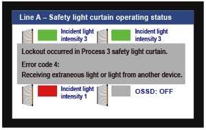
Error indication
The new series is also equipped with the error indication function, a well-received feature of our previous models. In an environment where a PC cannot be brought in or when a problem occurs at a remote location, the displayed error number lets you identify the cause of problem. This facilitates restoration work.
Indicator for improved work efficiency
The application indicator improves work efficiency in a variety of ways by providing support to work activities ranging from daily equipment operation to installation and maintenance. The indicator function can be switched between two options.
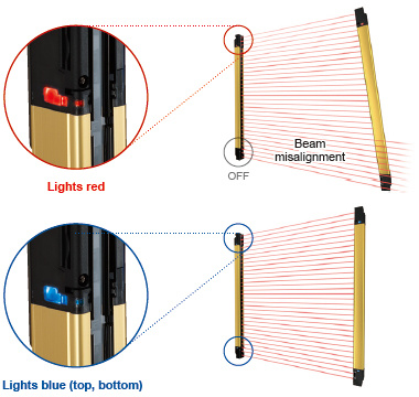
Beam axis adjustment mode
The color of the indicator notifies whether the beam axes of both top and bottom ends are aligned properly. The indicator is easy to see from any direction so mistakes can be prevented in a long-distance setup.
When beam axes of both top and bottom ends are aligned properly:
All application indicators light blue.
When beam axis of either of top end or bottom end is aligned:
All application indicators light blue.
When beam axis of either of top end or bottom end is aligned:
The indicators of only the aligned side light red.
When beam axes of both top and bottom ends are misaligned:
All application indicators are OFF. * When optical synchronization is set, only the indicator on the receiver lights up.
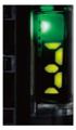
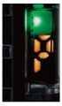
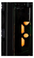
Application indicator mode
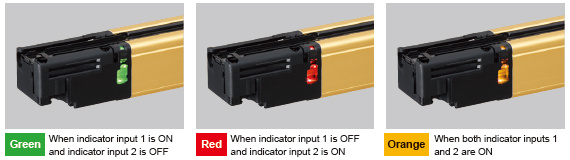
Can light and blink in three colors (green, red, and orange) according to an external input. The indicator can be used to indicate work instructions or equipment status.
* When optical synchronization is set, only the indicator on the receiver lights up.
*The DIP switches in the unit must be set to use this function.
For details, see the manual.
【COLUMN】
Stable light incidence indicator that even shows the amount of margin
The stable light incidence indicator is commonly used when installing a new safety light curtain to equipment or when checking if the existing safety light curtain is operating properly. Previously, however, even if the stable light incidence indicator was ON, there was no way of knowing whether there was an ample margin or the condition is close to unstable light incidence.
The SF4D series not only shows whether the light incidence is stable or unstable but also the amount of margin with a numeric display. Therefore, it is possible to numerically manage the stability margin of the safety light curtain. When the amount of received beam intensity decreases during equipment operation due to oil mist or other reasons, the digital display shows the stability margin of the safety light curtain. Thus, cleaning can be scheduled and conducted at the most suitable timing.
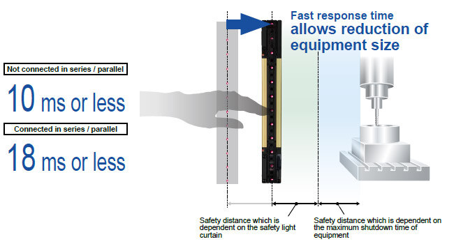
Fast response time 10 ms or less
The OFF response time of the control outputs (OSSD 1, OSSD 2) of the SF4D series is 10 ms or less (when not connected in series or in parallel).
[18 ms or less when connected in series or in parallel] The SF4D series contributes to the reduction of equipment size.
Regarding the response time by number of beams, see "Control output (OSSD 1, OSSD 2) OFF response times".
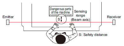
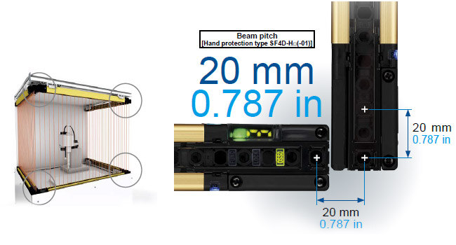
Dead zoneless design enables easy calculation of safe distance.
Inherits the dead zoneless design of the previous SF4B series. Even in an L-shaped layout or a U-shaped layout, the beam pitch does not change*, making calculation of the safe distance easier.
* Excluding the finger protection type SF4D-F□(-01).
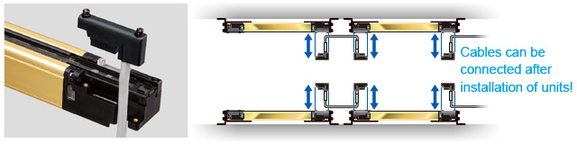
Easy to attach / detach front access cable
Uses the well-received front access cable of previous models. The cable can be attached and detached after the safety light curtain is installed on the equipment. This allows easy replacement in the event that the cable is damaged.
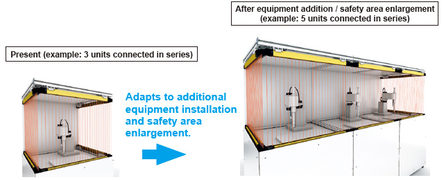
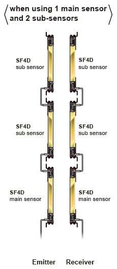
Series connection of up to 5 units
Up to five units (1 main sensor and 4 sub-sensors) can be connected in series, and the maximum number of beams has been increased to 256. This provides extra convenience when installing additional equipment, when increasing the detection width (protection height), and when using one system for protection of multiple locations.
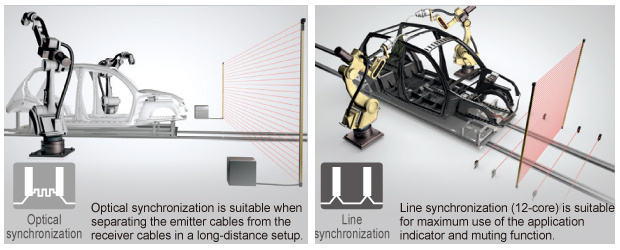
Selectable synchronization method and cable to suit various applications
When choosing and installing a safety light curtain, the synchronization method and cable can be selected flexibly according to the customer's specific application and needs, such as the basic configuration or safety-enhanced configuration with improved operability.
| Synchronization method | Optical synchronization | Line synchronization | |||
|---|---|---|---|---|---|
| Cable type | 5-core | 12-core | 8-core | 12-core | |
| Function | Interlock function | Software | ○(Software) | ○(Software) | |
| Lockout release function | ○ | ○ | ○ | ○ | |
| Test input function | ○ | ○ | ○ | ○ | |
| Auxiliary output (non-safety output) function | ○(Software) | ○(Software) | ○(Software) | ||
| External device monitor function | ○(Software) | ○(Software) | ○(Software) | ||
| Muting / Override function | Software | ○(Software) | |||
| Application indicator function | Software | ○(Software) | Software | ○(Software) | |
| Parallel interference prevention function | Software | ||||
| Fix blanking function | Software | Software | Software | Software | |
| Floating blanking function | Software | Software | Software | Software | |
○:Functional by default
Software:Functional when setting software is used
○(Software):Functional by default.
Function can be expanded when setting software is used
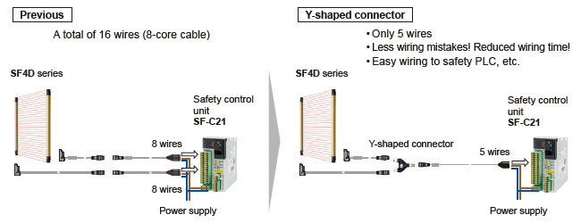
Y-shaped connector for further reduction of wiring
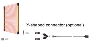
When 8-core cables and line synchronization are used, connection of only five cables is required when the Y-shaped connector (optional) is used.
This allows easy connection to a safety PLC or other devices, and also helps eliminate wiring mistakes and reduce the man-hours required for wiring.
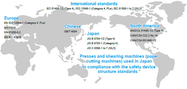
Global specifications for anywhere use in the world
The SF4D series' global specifications comply with the following standards.
*1: SF4D-□-01 only
Supports both PNP and NPN polarities
Every model in the SF4D series supports both PNP transistor output and NPN transistor output. Thus, the SF4D series products adapt to any control circuits used around the world, making it possible to use the product when PNP is installed overseas, when NPN sensors are replaced, when the positive pole is grounded in the factory, when moving equipment to overseas facilities, etc.
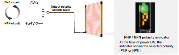
Easy change of polarity by simple cable connection
Connecting the output polarity setting cable to 0 V results in PNP output.
Connecting the output polarity setting cable to +24 V results in NPN output.
Configuration of simple safety circuit by combining a control unit
Easy compliance with control category 4 specifications.
Designed for optimum control of SF4D series.
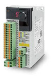
Safety control unit SF-C21
This safety controller does not require a knowledge of programming. The simple settings only require selection of an internal logic. A free software tool allows intuitive operation. Logic customization, monitoring, and simulation functions are also provided to enable surprisingly easy circuit building.
• Supports up to control category 4
• Supports PNP polarity
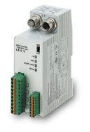
Connector connection control unit SF-C11
The wiring with the safety light curtain can be done easily with 8-core cable with connector. It reduces time for installation and replacement.
• Supports up to control category 4
• Supports presses used in Japan (shearing machines not supported)
• Supports both PNP and NPN
Thin control unit SF-C13
22.5 mm 0.886 in thinness has been realized.
Possible to install in a small space of the board.
• Supports up to control category 4
• Supports presses used in Japan (shearing machines not supported)
• Supports both PNP and NPN


[1]Safety light curtain
Mounting bracket and bottom cap cable are not supplied with the safety light curtain. Be sure to order them separately.
| Type | Model No. | Protective height (Note 2) | Beam pitch | Both end beam axes position | ||
|---|---|---|---|---|---|---|
| Japanese press machine or paper shearing machine compliant | When using as safety equipment for Chinese press machine or when using SF4D-□-01 for Japanese press machine or paper shearing machine | |||||
| A | B | C | ||||
| Finger protection type | SF4D-F15 | SF4D-F15-01 | 150 mm 5.906in | 140 mm 5.512 in | 10 mm 0.394 in | 5 mm 0.197 in |
| SF4D-F23 | SF4D-F23-01 | 230 mm 9.055 in | 220 mm 8.661 in | |||
| SF4D-F31 | SF4D-F31-01 | 310 mm 12.205 in | 300 mm 11.811 in | |||
| SF4D-F39 | SF4D-F39-01 | 390 mm 15.354 in | 380 mm 14.960 in | |||
| SF4D-F47 | SF4D-F47-01 | 470 mm 18.504 in | 460 mm 18.110 in | |||
| SF4D-F55 | SF4D-F55-01 | 550 mm 21.654 in | 540 mm 21.260 in | |||
| SF4D-F63 | SF4D-F63-01 | 630 mm 24.803 in | 620 mm 24.409 in | |||
| SF4D-F71 | SF4D-F71-01 | 710 mm 27.953 in | 700 mm 27.559 in | |||
| SF4D-F79 | SF4D-F79-01 | 790 mm 31.102 in | 780 mm 30.708 in | |||
| SF4D-F95 | SF4D-F95-01 | 950 mm 37.402 in | 940 mm 37.007 in | |||
| SF4D-F111 | SF4D-F111-01 | 1,110 mm 43.701 in | 1,100 mm 43.307 in | |||
| SF4D-F127 | SF4D-F127-01 | 1,270 mm 50.000 in | 1,260 mm 49.606 in | |||
| Hand protection type | SF4D-H8 | SF4D-H8-01 | 150 mm 5.906 in | 140 mm 5.512 in | 20 mm 0.787 in | 5 mm 0.197 in |
| SF4D-H12 | SF4D-H12-01 | 230 mm 9.055 in | 220 mm 8.661 in | |||
| SF4D-H16 | SF4D-H16-01 | 310 mm 12.205 in | 300 mm 11.811 in | |||
| SF4D-H20 | SF4D-H20-01 | 390 mm 15.354 in | 380 mm 14.960 in | |||
| SF4D-H24 | SF4D-H24-01 | 470 mm 18.504 in | 460 mm 18.110in | |||
| SF4D-H28 | SF4D-H28-01 | 550 mm 21.654 in | 540 mm 21.260 in | |||
| SF4D-H32 | SF4D-H32-01 | 630 mm 24.803 in | 620 mm 24.409 in | |||
| SF4D-H36 | SF4D-H36-01 | 710 mm 27.953 in | 700 mm 27.559 in | |||
| SF4D-H40 | SF4D-H40-01 | 790 mm 31.102 in | 780 mm 30.708 in | |||
| SF4D-H48 | SF4D-H48-01 | 950 mm 37.402 in | 940 mm 37.007 in | |||
| SF4D-H56 | SF4D-H56-01 | 1,110 mm 43.701 in | 1,100 mm 43.307 in | |||
| SF4D-H64 | SF4D-H64-01 | 1,270 mm 50.000 in | 1,260 mm 49.606 in | |||
| SF4D-H72 | SF4D-H72-01 | 1,430 mm 56.299 in | 1,420 mm 55.905 in | |||
| SF4D-H80 | SF4D-H80-01 | 1,590 mm 62.598 in | 1,580 mm 62.205 in | |||
| SF4D-H88 | SF4D-H88-01 | 1,750 mm 68.898 in | 1,740 mm 68.503 in | |||
| SF4D-H96 | SF4D-H96-01 | 1,910 mm 75.197 in | 1,900 mm 74.803 in | |||
| Arm / Foot protection type | SF4D-A4 | SF4D-A4-01 | 150 mm 5.906 in | 120 mm 4.724 in | 40 mm 1.575 in | 15 mm 0.591 in |
| SF4D-A6 | SF4D-A6-01 | 230 mm 9.055 in | 200 mm 7.874 in | |||
| SF4D-A8 | SF4D-A8-01 | 310 mm 12.205 in | 280 mm 11.024 in | |||
| SF4D-A10 | SF4D-A10-01 | 390 mm 15.354 in | 360 mm 14.173 in | |||
| SF4D-A12 | SF4D-A12-01 | 470 mm 18.504 in | 440 mm 17.323 in | |||
| SF4D-A14 | SF4D-A14-01 | 550 mm 21.654 in | 520 mm 20.472 in | |||
| SF4D-A16 | SF4D-A16-01 | 630 mm 24.803 in | 600 mm 23.622 in | |||
| SF4D-A18 | SF4D-A18-01 | 710 mm 27.953 in | 680 mm 26.772 in | |||
| SF4D-A20 | SF4D-A20-01 | 790 mm 31.102 in | 760 mm 29.921 in | |||
| SF4D-A24 | SF4D-A24-01 | 950 mm 37.402 in | 920 mm 36.220 in | |||
| SF4D-A28 | SF4D-A28-01 | 1,110 mm 43.701 in | 1,080 mm 42.520 in | |||
| SF4D-A32 | SF4D-A32-01 | 1,270 mm 50.000 in | 1,240 mm 48.819 in | |||
| SF4D-A36 | SF4D-A36-01 | 1,430 mm 56.299 in | 1,400 mm 55.118 in | |||
| SF4D-A40 | SF4D-A40-01 | 1,590 mm 62.598 in | 1,560 mm 61.417 in | |||
| SF4D-A44 | SF4D-A44-01 | 1,750 mm 68.898 in | 1,720 mm 67.716 in | |||
| SF4D-A48 | SF4D-A48-01 | 1,910 mm 75.197 in | 1,880 mm 74.016 in | |||
Notes:
1) The operating range is the possible setting distance between the emitter and the receiver.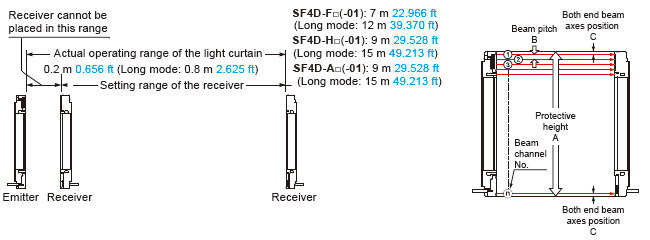
2) When using as a safety device for a press machine in China or when using SF4D-□-01 as a safety device for a press machine or paper shearing machine in Japan, the length from the center of the first beam channel to the center of the last beam channel become to be protective height.
[2]Mounting brackets
Mounting bracket is not supplied with the safety light curtain. Be sure to order it separately.
| Designation | Model No. | Description | |
|---|---|---|---|
| Beam adjustment mounting bracket | MS-SFD-1-5 | For mounting with M5 / M8 hexagon-socket head bolt | Mounting bracket for rear or side installation of safety light curtain. (4 pcs./set for emitter and receiver) Material: Cold rolled carbon steel (SPCC) |
| MS-SFD-1-6 | For mounting with M6 hexagon-socket head bolt | ||
| MS-SFD-1-8 | For mounting with M8 hexagon-socket head bolt | ||
| Dead zoneless beam adjustment mounting bracket (Note 1) | MS-SFD-3-6 | No deadspace mounting is possible in which mounting brackets do not extend beyond the protective height. (4 pcs./set for emitter and receiver) Material: Die-cast zinc alloy | |
| Intermediate supporting bracket (Note 2) | MS-SFB-2 | This bracket holds the safety light curtain at the middle. (2 pcs./set for emitter and receiver) Use when installing the safety light curtain in a location subject to vibration. Material: Die-cast zinc alloy | |
| SF4B-G compatible mounting bracket | MS-SFD-4BG | Mounting bracket for replacement of previous SF4B-□G□<V2> model with this device. (4 pcs./set for emitter and receiver) There is no need to change the mounting hole pitch. Material: Cold rolled carbon steel (SPCC) | |
Notes:
1) The required number for emitter and receiver varies depending on the number of beam channels.
2) When the number of beam channels is SF4D-F□(-01): 111 or more beam channels, SF4D-H□(-01): 56 or more beam channels, SF4D-A□(-01): 28 or more beam channels, one set is required.
Dead zoneless beam adjustment mounting bracket


Beam adjustment mounting bracket


Intermediate supporting bracket

SF4B-G compatible mounting bracket

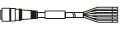
[3][4][5][6]Mating cable / Extension cable
Mating cable is not supplied with the safety light curtain. Be sure to order it separately.
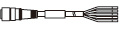
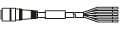
Standard components (5-core cable)
| Type | Appearance | Model No. | Description (Note 1) | ||||
|---|---|---|---|---|---|---|---|
Bottom cap cable | Discrete wire |
| SFD-CCB5-S | Length: 5 m 16.404 ft Net weight: 420 g approx. (2 cables) | Used for connecting to the safety light curtain and to other cables or the SF-C13 / SF-C21 control unit. 2 pcs./set for emitter and receiver | ||
| SFD-CCB10-S | Length: 10 m 32.808 ft Net weight: 830 g approx. (2 cables) | ||||||
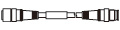
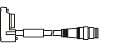
| Connector |
| SFD-CB05-S | Length: 0.5 m 1.640 ft Net weight: 75 g approx. (2 cables) | Used for connecting to the safety light curtain and to an Extension cable. 2 pcs./set for emitter and receiver Connector outer diameter: ø14 mm ø0.551 in max. M12 male connector | |||
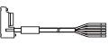
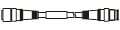
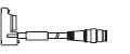
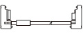
Extension cable | With connector on one end |
| SFD-CC3-S | Length: 3 m 9.843 ft Net weight: 260 g approx. (2 cables) | Used for connecting to the safety light curtain and to an Extension cable or the SF-C13 / SF-C21 control unit. 2 pcs./set for emitter and receiver Connector outer diameter: ø14 mm ø0.551 in max. M12 female connector | ||
| SFD-CC10-S | Length: 10 m 32.808 ft Net weight: 830 g approx. (2 cables) | ||||||
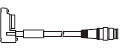
| With connectors on both ends | For emitter |
| SFD-CCJ10E-S | Length: 10 m 32.808 ft Net weight: 420 g approx. (1 cable) | 1 pc. for emitter Connector color: Gray | Used for connecting to an extension cable. Connector outer diameter: ø14 mm ø0.551 in max. M12 female-male connector | |
| For receiver | SFD-CCJ10D-S | Length: 10 m 32.808 ft Net weight: 440 g approx. (1 cable) | 1 pc. for receiver Connector color: Black | ||||


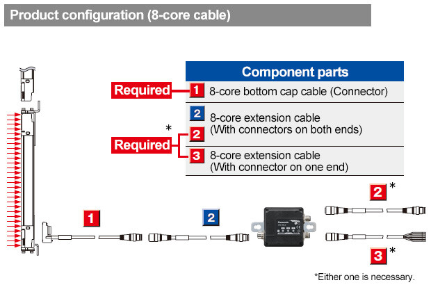
Standard components (8-core cable)
| Type | Appearance | Model No. | Description (Note 1) | ||||
|---|---|---|---|---|---|---|---|
Bottom cap cable | Discrete wire |
| SFD-CCB3 | Length: 3 m 9.843 ft Net weight: 290 g approx. (2 cables) | Used for connecting to the safety light curtain and to other cables or the SF-C13 / SF-C21 control unit. 2 pcs./set for emitter and receiver | ||
| SFD-CCB7 | Length: 7 m 22.966 ft Net weight: 620 g approx. (2 cables) | ||||||
| SFD-CCB10 | Length: 10 m 32.808 ft Net weight: 900 g approx. (2 cables) | ||||||
| SFD-CCB15 | Length: 15 m 49.213 ft Net weight: 1,300 g approx. (2 cables) | ||||||
| Connector |
| SFD-CB05 | Length: 0.5 m 1.640 ft Net weight: 80 g approx. (2 cables) | Used for connecting to the safety light curtain and to an extension cable or the SF-C11 control unit. 2 pcs./set for emitter and receiver Connector outer diameter: ø14 mm ø0.551 in max. M12 male connector | |||
| SFD-CB5 | Length: 5 m 16.404 ft Net weight: 480 g approx. (2 cables) | ||||||
| SFD-CB10 | Length: 10 m 32.808 ft Net weight: 950 g approx. (2 cables) | ||||||
Extension cable | With connector on one end |
| SFD-CC3 | Length: 3 m 9.843 ft Net weight: 290 g approx. (2 cables) | Used for connecting to the safety light curtain and to an extension cable or the SF-C13 / SF-C21 control unit. 2 pcs./set for emitter and receiver Connector outer diameter: ø14 mm ø0.551 in max. M12 female connector | ||
| SFD-CC10 | Length: 10 m 32.808 ft Net weight: 900 g approx. (2 cables) | ||||||
| With connectors on both ends | For emitter |
| SFB-CCJ3E | Length: 3 m 9.843 ft Net weight: 190 g approx. (1 cable) | 1 pc. for emitter Connector color: Gray | Used for connecting to an extension cable or the SF-C11 control unit. Connector outer diameter:ø14 mm ø0.551 in max. M12 female-male connector | |
| SFB-CCJ10E | Length: 10 m 32.808 ft Net weight: 580 g approx. (1 cable) | ||||||
| For receiver | SFB-CCJ3D | Length: 3 m 9.843 ft Net weight: 210 g approx. (1 cable) | 1 pc. for receiver Connector color: Black | ||||
| SFB-CCJ10D | Length: 10 m 32.808 ft Net weight: 600 g approx. (1 cable) | ||||||


Adapter cable
| Type | Appearance | Model No. | Description (Note 1) | ||||
|---|---|---|---|---|---|---|---|
Compatible cable | For SF4-AH□ (PNP type) |
| SFD-CB05-A-P | Length: 0.5 m 1.640 ft Net weight: 80 g approx. (2 cables) | Used to allow connector cables connected to previous safety light curtains (at the control circuit side) to be smoothly adapted to the SF4D series. Two cables per set for emitter and receiver Connector outer diameter: ø14 mm ø0.551 in max. M12 male connector | ||
| For SF4-AH□-N (NPN type) | SFD-CB05-A-N | ||||||
Note:
1) Where the cable color has not been specified, it is black for emitter, gray with black line for outer diameter is ø5.7 mm ø0.224 in or ø6 mm ø0.236 in, min. bending radius is R6 mm R0.236 in. However, the minimum bending radius of the cable with the protective tube SFPD-A10 attached is R55 mm R2.165 in.
[7][8][9][10]Mating cable / Extension cable / Cables for series connection / Protective tube
Mating cable is not supplied with the safety light curtain. Be sure to order it separately.
Standard components(12-core cable)
| Type | Appearance | Model No. | Description (Note 1) | ||||
|---|---|---|---|---|---|---|---|
Bottom cap cable | Discrete wire |
| SFD-CCB3-MU | Length: 3 m 9.843 ft Net weight: 340 g approx. (2 cables) | Used for connecting to the safety light curtain and to other cables or the SF-C13 / SF-C21 control unit. 2 pcs./set for emitter and receiver | ||
| SFD-CCB7-MU | Length: 7 m 22.966 ft Net weight: 700 g approx. (2 cables) | ||||||
| SFD-CCB10-MU | Length: 10 m 32.808 ft Net weight: 980 g approx. (2 cables) | ||||||
| Connector |
| SFD-CB05-MU | Length: 0.5 m 1.640 ft Net weight: 95 g approx. (2 cables) | Used for connecting to the safety light curtain and to an Extension cable. 2 pcs./set for emitter and receiver Connector outer diameter: ø16 mm ø0.630 in max. | |||
Extension cable | With connector on one end |
| SFD-CC3-MU | Length: 3 m 9.843 ft Net weight: 340 g approx. (2 cables) | Used for connecting to the safety light curtain and to an Extension cable or the SF-C13 / SF-C21 control unit. 2 pcs./set for emitter and receiver Connector outer diameter: ø16 mm ø0.630 in max. | ||
| SFD-CC7-MU | Length: 7 m 22.966 ft Net weight: 700 g approx. (2 cables) | ||||||
| SFD-CC10-MU | Length: 10 m 32.808 ft Net weight: 980 g approx. (2 cables) | ||||||
| With connectors on both ends | For emitter |
| SFB-CCJ3E-MU | Length: 3 m 9.843 ft Net weight: 190 g approx. (1 cable) | 1 pc. for emitter Connector color: Gray | Used for connecting to an extension cable. Connector outer diameter: ø16 mm ø0.630 in max. | |
| SFB-CCJ10E-MU | Length: 10 m 32.808 ft Net weight: 660 g approx. (1 cable) | ||||||
| For receiver | SFB-CCJ3D-MU | Length: 3 m 9.843 ft Net weight: 210 g approx. (1 cable) | 1 pc. for receiver Connector color: Black | ||||
| SFB-CCJ10D-MU | Length: 10 m 32.808 ft Net weight: 680 g approx. (1 cable) | ||||||


Cable for series connection
| Type | Appearance | Model No. | Description (Note 1) | ||
|---|---|---|---|---|---|
Cable for series connection |
| SFD-CSL005 | Length: 0.05 m 0.164 ft Net weight: 35 g approx. (2 cables) | Used to connect safety light curtains in series Two cables per set for emitter and receiver (common for emitter and receiver) Cable color: Gray with black line (common for emitter and receiver) | |
| SFD-CSL01 | Length: 0.1 m 0.328 ft Net weight: 40 g approx. (2 cables) | ||||
| SFD-CSL05 | Length: 0.5 m 1.640 ft Net weight: 80 g approx. (2 cables) | ||||
| SFD-CSL1 | Length: 1 m 3.280 ft Net weight: 130 g approx. (2 cable) | ||||
| SFD-CSL5 | Length: 5 m 16.404 ft Net weight: 480 g approx. (2 cables) | ||||
| SFD-CSL10 | Length: 10 m 32.808 ft Net weight: 950 g approx. (2 cables) | ||||

protective tube
| Type | Appearance | Model No. | Description (Note 1) | ||
|---|---|---|---|---|---|
protective tube |
| SFPD-A10 | Tube length: 10 m 32.808 ft Net weight: 220 g approx.(1 cable) | Protective tubes must be installed to the cables when SF4D-□-01 is used as a safety device for a press or shearing machine (paper cutting machine) in Japan. Outside diameter: ø13 mm ø0.512 in approx., Inside diameter: ø9 mm ø0.354 in Material: Polypropylene | |

Note:
1) Where the cable color has not been specified, it is black for emitter, gray with black line for outer diameter is ø5.7 mm ø0.224 in or ø6 mm ø0.236 in, min. bending radius is R6 mm R0.236 in. However, the minimum bending radius of the cable with the protective tube SFPD-A10 attached is R55 mm R2.165 in.
Option
Control units
| Designation | Appearance | Model No. | Application cable | Description (Note) |
|---|---|---|---|---|
| Safety control unit |
| SF-C21 | Safety Light Curtain Mating cable:SFD-CCB□ Extension cable:SFD-CC□ | Use a discrete wire cable to connect to the safety light curtain. Logic customization, monitoring, and simulation functions are also provided. Compatible with up to Control Category 4. |
| Connector connection type control unit |
| SF-C11 | Safety Light Curtain Mating cable:SFD-CB□ Extension cable:SFB-CCJ□ (M12 connector) | Use 8-core cable with connector to connect to the safety light curtain. Muting function cannot be used. Compatible with up to Control Category 4. Supports presses used in Japan when combined with SF4D-□-01 (shearing machines not supported) |
| Slim type control unit |
| SF-C13 | Safety Light Curtain Mating cable:SFD-CCB□ Extension cable:SFD-CC□ | Use a discrete wire cable to connect to the safety light curtain. Muting function can be used. Compatible with up to Control Category 4. Supports presses used in Japan when combined with SF4D-□-01 (shearing machines not supported) |


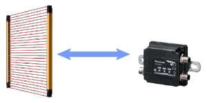
IO-Link Communication Unit
| Type | Appearance | Model No. | Description |
|---|---|---|---|
| IO-Link Communication Unit | 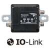
| SFD-WL3 | For use with SF4D series This unit enables the confirmation of various settings and operating status of the SF4D series from a host device using IO-Link communication. It can also save the setting information of the connected SF4D series unit. |
Example of configuration
Safety output and IO-Link communication are separated from each other so that the safety light curtain can be monitored without any alteration of the safety circuit.
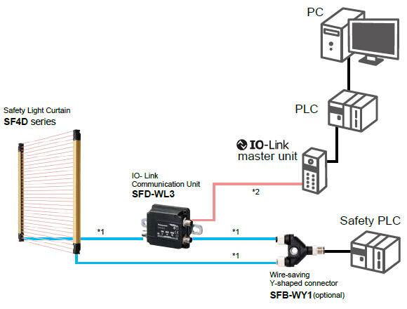
*1: 8-core cable for safety light curtain (optional)
*2: 4-core cable with M12 connector (commercially available product) (Note)
Note : The product and IO-Link master unit must be connected with a cable of 0.3 mm2 or more. The total length of the cable must not exceed 20 m 65.517 ft.
Remote monitoring of safety light curtain status
Confirmation of light intensity margin
Incident light intensity information enables the determination of whether maintenance is necessary or not. This helps prevent shut-down of the line due to light beam deviation or dirty sensor. The information is also useful in conducting remote inspection or the like at the start of work.
Confirmation of error history
If an error occurs, the source of the error and its detail can be checked remotely, thus facilitating the identification of the problem location and analysis of the cause.
Storage of setting data, restoration of settings
One-touch setting after replacement
The setting data stored in the communication unit allows one-touch restoration of the settings when the safety light curtain is replaced.
Example of IO-Link data output
Process data
Service data
- Light received / blocked information
- Stable / unstable incident light information
- Extraneous light information
- Emitter / receiver lockout information
- Incident light intensity information (OFF, 1, 2, 3)
- OSSD output information
- Communication control status
- Number of units in series connection
- Safety light curtain main unit information
- SFD-WL3 main unit information
- Incident light intensity information of individual beams (32 levels)
- Error code
Mating cable
| Type | Model No. | Description | ||||
|---|---|---|---|---|---|---|
| [1] Bottom cap cable | Connector | SFD-CB05 | Length: 0.5 m 1.640 ft Net weight: 80 g approx. (2 cables) | Used for connecting to the safety light curtain and to an extension cable or the SF-C11 control unit. 2 pcs./set for emitter and receiver Connector outer diameter: ø14 mm ø0.551 in max. | ||
| SFD-CB5 | Length: 5 m 16.404 ft Net weight: 480 g approx. (2 cables) | |||||
| SFD-CB10 | Length: 10 m 32.808 ft Net weight: 950 g approx. (2 cables) | |||||
| [2] Extension cable | With connectors on both ends | For emitter | SFB-CCJ3E | Length: 3 m 9.843 ft Net weight: 190 g approx. (1 cable) | 1 pc. for emitter Connector color: Gray | Used for connecting to an extension cable or the SF-C11 control unit. Connector outer diameter:ø14 mm ø0.551 in max. |
| SFB-CCJ10E | Length: 10 m 32.808 ft Net weight: 580 g approx. (1 cable) | |||||
| For receiver | SFB-CCJ3D | Length: 3 m 9.843 ft Net weight: 210 g approx. (1 cable) | 1 pc. for receiver Connector color: Black | |||
| SFB-CCJ10D | Length: 10 m 32.808 ft Net weight: 600 g approx. (1 cable) | |||||
| [3] Extension cable | With connector on one end | SFD-CC3 | Length: 3 m 9.843 ft Net weight: 290 g approx. (2 cables) | Used for connecting to the safety light curtain and to an extension cable or the SF-C13 / SF-C21 control unit. 2 pcs./set for emitter and receiver Connector outer diameter: ø14 mm ø0.551 in max. | ||
| SFD-CC10 | Length: 10 m 32.808 ft Net weight: 900 g approx. (2 cables) | |||||
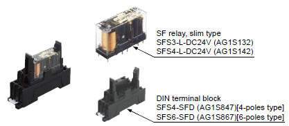
Recommended safety relay
SF relay, slim type
SF series
Note:Please contactour sales officefor details on the recommended products.
| Type | With LED indicator | |
|---|---|---|
| Model No. | SFS3-L-DC24V | SFS4-L-DC24V |
| Part No. | AG1S132 | AG1S142 |
| Contact arrangement | 3a1b | 4a2b |
| Rated nominal switching capacity | 6A/250V AC、6A/30V DC | |
| Min. switching capacity | 1mA/5V DC | |
| Coil rating | 15mA/24V DC | 20.8mA/24V DC |
| Rated power consumption | 360mW | 500mW |
| Operation time | 20ms or less | |
| Release time | 20ms or less | |
| Ambient temperature | -40 to +85 ℃ -40 to + 185 ℉ (Humidity: 5 to 85 % RH) | |
| Applicable certifications | UL/c-UL, TÜV, Korea S-mark | |
Communication module
| Type | Appearance | Model No. | Description |
|---|---|---|---|
| Communication module |
| SF4D-TM1 | The setting software, Configurator Safety Light Curtain, is required when using the SF4D-TM1 communication module. The setting software can be downloaded free from our website. USB cable is not provided with the product. USB2.0 cable (A: Mini-B) must be prepared by the user. <In the case of SF4D-F□/H□/A□> The communication module serves as a conversion module for the connection of a PC to the SF4D series for changing function settings and monitoring statuses (light incidence / light blockage, lockout, etc.). The communication module can also be used to copy settings from SF4D series products without the connection of a PC. <In the case of SF4D-□-01> The communication module serves as a conversion module for the connection of a PC to the SF4D series for monitoring statuses (light incidence / light blockage, lockout, etc.). The communication module cannot be used by itself. |
(Note) :
Please make sure to connect SF4D series Ver.3.0 manufactured after March 17, 2020 with SF4D-TM1 Ver. 2.0 manufactured after December 2019.
Please refer to the "Cautions For Use" page for version identification.
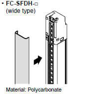
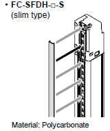
Front protection cover
Protects sensing surface of the safety light curtain from flying objects such as welding spatter.
The operating range reduces when the front protection cover is used.
| Applicable beam channels | Front protection cover (wide type)(Note 1) | Front protection cover (slim type)(Note 1) | |||
|---|---|---|---|---|---|
| Finger | Hand | Arm/ Foot | Model No. | Model No. | |
| 15 | 8 | 4 | FC-SFDH-8 | FC-SFDH-8-S | |
| 23 | 12 | 6 | FC-SFDH-12 | FC-SFDH-12-S | |
| 31 | 16 | 8 | FC-SFDH-16 | FC-SFDH-16-S | |
| 39 | 20 | 10 | FC-SFDH-20 | FC-SFDH-20-S | |
| 47 | 24 | 12 | FC-SFDH-24 | FC-SFDH-24-S | |
| 55 | 28 | 14 | FC-SFDH-28 | FC-SFDH-28-S | |
| 63 | 32 | 16 | FC-SFDH-32 | FC-SFDH-32-S | |
| 71 | 36 | 18 | FC-SFDH-36 | FC-SFDH-36-S | |
| 79 | 40 | 20 | FC-SFDH-40 | FC-SFDH-40-S | |
| 95 | 48 | 24 | FC-SFDH-48 | FC-SFDH-48-S | |
| 111 | 56 | 28 | FC-SFDH-56 | FC-SFDH-56-S | |
| 127 | 64 | 32 | FC-SFDH-64 | FC-SFDH-64-S | |
| - | 72 | 36 | FC-SFDH-72 | FC-SFDH-72-S | |
| - | 80 | 40 | FC-SFDH-80 | FC-SFDH-80-S | |
| - | 88 | 44 | FC-SFDH-88 | FC-SFDH-88-S | |
| - | 96 | 48 | FC-SFDH-96 | FC-SFDH-96-S | |
Note 1) The model Nos. given above denote a single unit, not a pair of units. 2 units are required for use in mounting to the emitter / receiver.
・Operating range
| Front protection cover | Operating range(Note1) | |||
|---|---|---|---|---|
| Short mode | Long mode | |||
| Finger | FC-SFDH-□ (wide type) FC-SFDH-□-S (slim type) | Only emitter | 0.2 to 6m | 0.8 to 9.5m |
| Only receiver | 0.2 to 6m | 0.8 to 9.5m | ||
| Both | 0.2 to 5.5m | 0.8 to 9m | ||
| Hand, Arm/Foot | FC-SFDH-□ (wide type) FC-SFDH-□-S (slim type) | Only emitter | 0.2 to 7.5m | 0.8 to 12m |
| Only receiver | 0.2 to 7.5m | 0.8 to 12m | ||
| Both | 0.2 to 7m | 0.8 to 11m | ||
Note 1) The operating range is the possible setting distance between the emitter and the receiver.
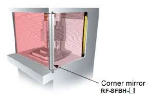
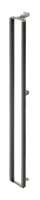
Corner mirror
Normally for an L-shaped or U-shaped installation, 2 or 3 sets of safety light curtains are needed. With the use of a corner mirror reflecting the light, one set of safety light curtain is possible for L-shaped or U-shaped installation.
| Applicable beam channels | Corner mirror (Note 1) | ||||
|---|---|---|---|---|---|
| Finger | Hand | Arm/ Foot | Appearance | Model No. | Effective reflective surface |
| 15 | 8 | 4 |
| RF-SFBH-8 | 173×72mm |
| 23 | 12 | 6 | RF-SFBH-12 | 236×72mm | |
| 31 | 16 | 8 | RF-SFBH-16 | 316×72mm | |
| 39 | 20 | 10 | RF-SFBH-20 | 396×72mm | |
| 47 | 24 | 12 | RF-SFBH-24 | 476×72mm | |
| 55 | 28 | 14 | RF-SFBH-28 | 556×72mm | |
| 63 | 32 | 16 | RF-SFBH-32 | 636×72mm | |
| 71 | 36 | 18 | RF-SFBH-36 | 716×72mm | |
| 79 | 40 | 20 | RF-SFBH-40 | 796×72mm | |
| 95 | 48 | 24 | RF-SFBH-48 | 956×72mm | |
| 111 | 56 | 28 | RF-SFBH-56 | 1,116×72mm | |
| 127 | 64 | 32 | RF-SFBH-64 | 1,276×72mm | |
| - | 72 | 36 | RF-SFBH-72 | 1,436×72mm | |
| - | 80 | 40 | RF-SFBH-80 | 1,596×72mm | |
| - | 88 | 44 | RF-SFBH-88 | 1,756×72mm | |
| - | 96 | 48 | RF-SFBH-96 | 1,916×72mm | |
Note 1) The model Nos. given above denote a single unit, not a pair of units.
・Percent decline of the sensing range
| With 1 mirror | Declined to 90% |
|---|---|
| With 2 mirrors | Declined to 80% |
| With 3 mirrors | Declined to 70% |
Y-shaped connector
| Type | Appearance | Model No. | Description | |
|---|---|---|---|---|
| Wire-saving Y-shaped connector |
| SFB-WY1 | Wire-saving connector for standard components (8-core cable). Cables of emitter and receiver are consolidated into one cable for wire-saving. Wiring has +24 V, 0 V, OSSD 1, OSSD 2, output polarity setting wire, and lockout release input. [Power wire and synchronization wire are connected inside the connector. Interlock is disabled (automatic reset).] Net weight: 35 g approx. M12 female-male connector | |
| Cable with connector on one side |
| WY1-CCN3 | Cable length: 3 m 9.843 ft Net weight: 200 g approx. (1 cable) | Mating cable for Y-shaped connector Cable color: Gray (with black line) Connector color: Black The min. bending radius: R6 mm R0.236 in M12 female connector |
| WY1-CCN10 | Cable length: 10 m 32.808 ft Net weight: 620 g approx. (1 cable) | |||


By using the Y-shaped connector, the least required wires such as power or safety output are consolidated into one cable.
Man-hours taken for wiring is eliminated to the minimum. Construction times as well as wiring mistakes are greatly reduced.
Refer to the instruction manual of Y-shaped connector and safety control unit for more detail such as installation of Y-shaped connector, terminal wiring, and wiring example.
Test rod / Laser alignment tool
| Designation | Model No. | Description |
|---|---|---|
| Test rod ø14 | SF4B-TR14 | Min. sensing object for regular checking (ø14 mm ø0.551 in), with finger protection type (min. sensing object ø14 mm ø0.551 in) |
| Test rod ø25 | SF4B-TR25 | Min. sensing object for regular checking (ø25 mm ø0.984 in), with hand protection type (min. sensing object ø25 mm ø0.984 in) |
| Test rod ø45 | SF4B-TR45 | Min. sensing object for regular checking (ø45 mm ø1.772 in), with arm / foot protection type (min. sensing object ø45 mm ø1.772 in) |
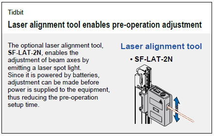
| Laser alignment tool | SF-LAT-2N | Allows easy beam axis alignment using easy-to-see laser beam |
Laser alignment tool
• SF-LAT-2N
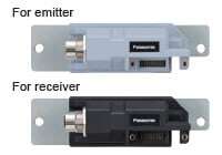
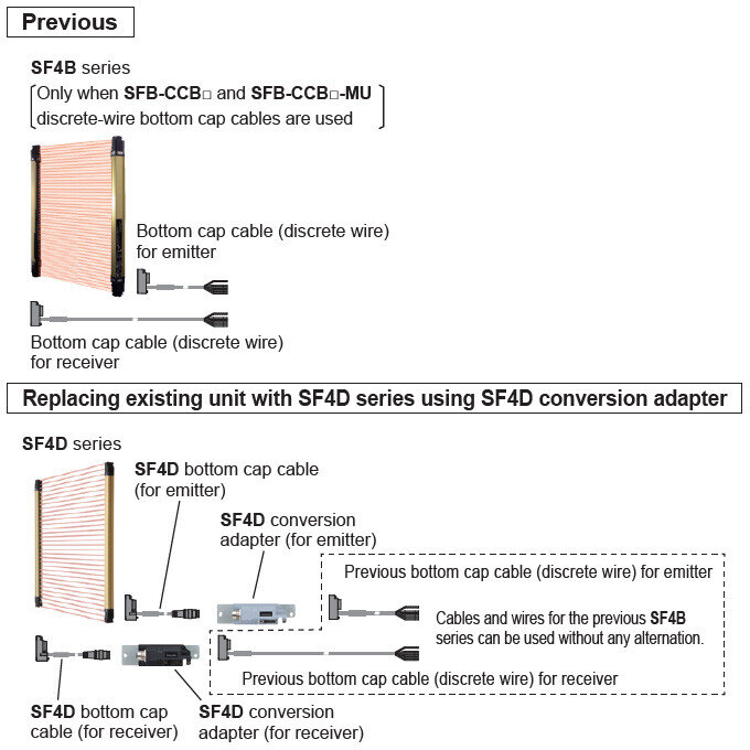
SF4D conversion adapter (For replacing SF4B series with SF4D series)
| Type | Appearance | Model No. | Description (Note) | ||
|---|---|---|---|---|---|
| SF4D conversion adapter (Note) | For 8-core cable |
| SFD-J4B | This unit replaces the previous SF4B series (only when SFB-CCB□ and SFB-CCB□-MU discrete-wire bottom cap cables are used). The existing mounting holes, discrete-wire bottom cap cables and other wires for the previous SF4B series can be used to allow for easy and smooth installation. 1 set (one for emitter and one for receiver) Female connector (8-core: M12, 12-core: M14) | |
| For 12-core cable | SFD-J4B-MU | ||||
| SF4D bottom cap cable | For 8-core cable |
| SFD-CB05 | Length: 0.5 m 1.640 ft Net weight: 80 g approx. (2 cables) | Used for connecting to the SF4D series main unit and to SF4D conversion adapter. 2 cables/set for emitter and receiver Cable color: Gray for emitter Gray with black line for receiver Min. bending radius: R6 mm Male connector (8-core: M12, 12-core: M14) |
| For 12-core cable | SFD-CB05-MU | Length: 0.5 m 1.640 ft Net weight: 95 g approx. (2 cables) | |||
Note : This product is made to order.
Specifications
- Safety light curtain individual specifications
- Safety light curtain common specifications
- IO-Link Communication Unit
- Communication module
- Laser alignment tool
- Corner mirror
- SF4D conversion adapter
Safety light curtain individual specifications
SF4D-F□(-01)(Finger protection type)
| Type | Min. sensing object ø14 mm ø0.551 in (10 mm 0.394 in beam pitch) | ||||
|---|---|---|---|---|---|
| Model No. | SF4D-F15(-01) | SF4D-F23(-01) | SF4D-F31(-01) | SF4D-F39(-01) | |
| Number of beam channels | 15 | 23 | 31 | 39 | |
| Protective height (Note 2) | 150 mm 5.906 in | 230 mm 9.055 in | 310 mm 12.205 in | 390 mm 15.354 in | |
| When using as safety equipment for Chinese press machine or when using SF4D-□-01 for Japanese press machine or paper shearing machine | 140 mm 5.512 in | 220 mm 8.661 in | 300 mm 11.811 in | 380 mm 14.961 in | |
| Current consumption | Emitter:110 mA or less Receiver:130 mA or less | Emitter:120 mA or less Receiver:130 mA or less | Emitter:120 mA or less Receiver:140 mA or less | ||
| PFHD | 1.21×10⁻⁹ | 1.48×10⁻⁹ | 1.80×10⁻⁹ | 2.07×10⁻⁹ | |
| MTTFD | 1,031 years or more | 833 years or more | 672 years or more | 582 years or more | |
| Net weight (Total of emitter and receiver) | 270g approx. | 470g approx. | 680g approx. | 890g approx. | |
| Type | Min. sensing object ø14 mm ø0.551 in (10 mm 0.394 in beam pitch) | ||||
|---|---|---|---|---|---|
| Model No. | SF4D-F47(-01) | SF4D-F55(-01) | SF4D-F63(-01) | SF4D-F71(-01) | |
| Number of beam channels | 47 | 55 | 63 | 71 | |
| Protective height (Note 2) | 470 mm 18.504 in | 550 mm 21.654 in | 630 mm 24.803 in | 710 mm 27.953 in | |
| When using as safety equipment for Chinese press machine or when using SF4D-□-01 for Japanese press machine or paper shearing machine | 460 mm 18.110 in | 540 mm 21.260 in | 620 mm 24.409 in | 700 mm 27.559 in | |
| Current consumption | Emitter:120 mA or less Receiver:140 mA or less | Emitter:120 mA or less Receiver:150 mA or less | |||
| PFHD | 2.40×10⁻⁹ | 2.66×10⁻⁹ | 2.99×10⁻⁹ | 3.25×10⁻⁹ | |
| MTTFD | 498 years or more | 447 years or more | 396 years or more | 363 years or more | |
| Net weight (Total of emitter and receiver) | 1,100g approx. | 1,300g approx. | 1,500g approx. | 1,700g approx. | |
| Type | Min. sensing object ø14 mm ø0.551 in (10 mm 0.394 in beam pitch) | ||||
|---|---|---|---|---|---|
| Model No. | SF4D-F79(-01) | SF4D-F95(-01) | SF4D-F111(-01) | SF4D-F127(-01) | |
| Number of beam channels | 79 | 95 | 111 | 127 | |
| Protective height (Note 2) | 790 mm 31.102 in | 950 mm 37.402 in | 1,110 mm 43.701 in | 1,270 mm 50.000 in | |
| When using as safety equipment for Chinese press machine or when using SF4D-□-01 for Japanese press machine or paper shearing machine | 780 mm 30.709 in | 940 mm 37.008 in | 1,100 mm 43.307 in | 1,260 mm 49.606 in | |
| Current consumption | Emitter:120 mA or less Receiver:150 mA or less | Emitter:120 mA or less Receiver:160 mA or less | Emitter:120 mA or less Receiver:170 mA or less | Emitter:120 mA or less Receiver:180 mA or less | |
| PFHD | 3.58×10⁻⁹ | 4.17×10⁻⁹ | 4.76×10⁻⁹ | 5.36×10⁻⁹ | |
| MTTFD | 328 years or more | 281 years or more | 245 years or more | 217 years or more | |
| Net weight (Total of emitter and receiver) | 1,900g approx. | 2,300g approx. | 2,800g approx. | 3,200g approx. | |
Notes:
1) Where measurement conditions have not been specified precisely, the conditions used were an ambient temperature of +20 ℃ +68 ℉.
PFHD: Probability of Dangerous Failure per Hour, MTTFD: Mean Time to Dangerous Failure (in years).
2) When using as a safety device for a press machine in China or when using SF4D-□-01 as a safety device for a press machine or paper shearing machine in Japan, the length from the center of the first beam channel to the center of the last beam channel become to be protective height.
SF4D-H□(-01)(Hand protection type)
| Type | Min. sensing object ø25 mm ø0.984 in (20 mm 0.787 in beam pitch) | ||||
|---|---|---|---|---|---|
| Model No. | SF4D-H8(-01) | SF4D-H12(-01) | SF4D-H16(-01) | SF4D-H20(-01) | |
| Number of beam channels | 8 | 12 | 16 | 20 | |
| Protective height (Note 2) | 150 mm 5.906 in | 230 mm 9.055 in | 310 mm 12.205 in | 390 mm 15.354 in | |
| When using as safety equipment for Chinese press machine or when using SF4D-□-01 for Japanese press machine or paper shearing machine | 140 mm 5.512 in | 220 mm 8.661 in | 300 mm 11.811 in | 380 mm 14.961 in | |
| Current consumption | Emitter:100 mA or less, Receiver:120 mA or less | ||||
| PFHD | 9.57×10⁻¹⁰ | 1.12×10⁻⁹ | 1.26×10⁻⁹ | 1.40×10⁻⁹ | |
| MTTFD | 1,340 years or more | 1,119 years or more | 988 years or more | 881 years or more | |
| Net weight (Total of emitter and receiver) | 270g approx. | 470g approx. | 680g approx. | 890g approx. | |
| Type | Min. sensing object ø25 mm ø0.984 in (20 mm 0.787 in beam pitch) | ||||
|---|---|---|---|---|---|
| Model No. | SF4D-H24(-01) | SF4D-H28(-01) | SF4D-H32(-01) | SF4D-H36(-01) | |
| Number of beam channels | 24 | 28 | 32 | 36 | |
| Protective height (Note 2) | 470 mm 18.504 in | 550 mm 21.654 in | 630 mm 24.803 in | 710 mm 27.953 in | |
| When using as safety equipment for Chinese press machine or when using SF4D-□-01 for Japanese press machine or paper shearing machine | 460 mm 18.110 in | 540 mm 21.260 in | 620 mm 24.409 in | 700 mm 27.559 in | |
| Current consumption | Emitter:100 mA or less Receiver:130 mA or less | Emitter:110 mA or less Receiver:130 mA or less | Emitter:120 mA or less Receiver:130 mA or less | ||
| PFHD | 1.56×10⁻⁹ | 1.73×10⁻⁹ | 1.87×10⁻⁹ | 2.04×10⁻⁹ | |
| MTTFD | 782 years or more | 701 years or more | 647 years or more | 591 years or more | |
| Net weight (Total of emitter and receiver) | 1,100g approx. | 1,300g approx. | 1,500g approx. | 1,700g approx. | |
| Type | Min. sensing object ø25 mm ø0.984 in (20 mm 0.787 in beam pitch) | ||||
|---|---|---|---|---|---|
| Model No. | SF4D-H40(-01) | SF4D-H48(-01) | SF4D-H56(-01) | SF4D-H64(-01) | |
| Number of beam channels | 40 | 48 | 56 | 64 | |
| Protective height (Note 2) | 790 mm 31.102 in | 950 mm 37.402 in | 1,110 mm 43.701 in | 1,270 mm 50.000 in | |
| When using as safety equipment for Chinese press machine or when using SF4D-□-01 for Japanese press machine or paper shearing machine | 780 mm 30.709 in | 940 mm 37.008 in | 1,100 mm 43.307 in | 1,260 mm 49.606 in | |
| Current consumption | Emitter:120 mA or less Receiver:140 mA or less | Emitter:120 mA or less Receiver:150 mA or less | |||
| PFHD | 2.17×10⁻⁹ | 2.48×10⁻⁹ | 2.78×10⁻⁹ | 3.09×10⁻⁹ | |
| MTTFD | 552 years or more | 481 years or more | 426 years or more | 383 years or more | |
| Net weight (Total of emitter and receiver) | 1,900g approx. | 2,300g approx. | 2,800g approx. | 3,200g approx. | |
| Type | Min. sensing object ø25 mm ø0.984 in (20 mm 0.787 in beam pitch) | ||||
|---|---|---|---|---|---|
| Model No. | SF4D-H72(-01) | SF4D-H80(-01) | SF4D-H88(-01) | SF4D-H96(-01) | |
| Number of beam channels | 72 | 80 | 88 | 96 | |
| Protective height (Note 2) | 1,430 mm 56.299 in | 1,590 mm 62.598 in | 1,750 mm 68.898 in | 1,910 mm 75.197 in | |
| When using as safety equipment for Chinese press machine or when using SF4D-□-01 for Japanese press machine or paper shearing machine | 1,420 mm 55.906 in | 1,580 mm 62.205 in | 1,740 mm 68.504 in | 1,900 mm 74.803 in | |
| Current consumption | Emitter:120 mA or less Receiver:150 mA or less | Emitter:120 mA or less Receiver:160 mA or less | |||
| PFHD | 3.39×10⁻⁹ | 3.69×10⁻⁹ | 4.00×10⁻⁹ | 4.30×10⁻⁹ | |
| MTTFD | 347 years or more | 318 years or more | 293 years or more | 272 years or more | |
| Net weight (Total of emitter and receiver) | 3,600g approx. | 4,000g approx. | 4,400g approx. | 4,800g approx. | |
Notes:
1) Where measurement conditions have not been specified precisely, the conditions used were an ambient temperature of +20 ℃ +68 ℉.
PFHD: Probability of Dangerous Failure per Hour, MTTFD: Mean Time to Dangerous Failure (in years).
2) When using as a safety device for a press machine in China or when using SF4D-□-01 as a safety device for a press machine or paper shearing machine in Japan, the length from the center of the first beam channel to the center of the last beam channel become to be protective height.
SF4D-A□(-01)(Arm / Foot protection type)
| Type | Min. sensing object ø45 mm ø1.772 in (40 mm 1.575 in beam pitch) | ||||
|---|---|---|---|---|---|
| Model No. | SF4D-A4(-01) | SF4D-A6(-01) | SF4D-A8(-01) | SF4D-A10(-01) | |
| Number of beam channels | 4 | 6 | 8 | 10 | |
| Protective height (Note 2) | 150 mm 5.906 in | 230 mm 9.055 in | 310 mm 12.205 in | 390 mm 15.354 in | |
| When using as safety equipment for Chinese press machine or when using SF4D-□-01 for Japanese press machine or paper shearing machine | 120 mm 4.724 in | 200 mm 7.874 in | 280 mm 11.024 in | 360 mm 14.173 in | |
| Current consumption | Emitter:100 mA or less, Receiver:120 mA or less | ||||
| PFHD | 8.29×10⁻¹⁰ | 9.34×10⁻¹⁰ | 1.01×10⁻⁹ | 1.11×10⁻⁹ | |
| MTTFD | 1,577 years or more | 1,378 years or more | 1,267 years or more | 1,136 years or more | |
| Net weight (Total of emitter and receiver) | 270g approx. | 470g approx. | 680g approx. | 890g approx. | |
| Type | Min. sensing object ø45 mm ø1.772 in (40 mm 1.575 in beam pitch) | ||||
|---|---|---|---|---|---|
| Model No. | SF4D-A12(-01) | SF4D-A14(-01) | SF4D-A16(-01) | SF4D-A18(-01) | |
| Number of beam channels | 12 | 14 | 16 | 18 | |
| Protective height (Note 2) | 470 mm 18.504 in | 550 mm 21.654 in | 630 mm 24.803 in | 710 mm 27.953 in | |
| When using as safety equipment for Chinese press machine or when using SF4D-□-01 for Japanese press machine or paper shearing machine | 440 mm 17.323 in | 520 mm 20.472 in | 600 mm 23.622 in | 680 mm 26.772 in | |
| Current consumption | Emitter:100 mA or less, Receiver:130 mA or less | ||||
| PFHD | 1.18×10⁻⁹ | 1.29×10⁻⁹ | 1.36×10⁻⁹ | 1.46×10⁻⁹ | |
| MTTFD | 1,060 years or more | 966 years or more | 910 years or more | 840 years or more | |
| Net weight (Total of emitter and receiver) | 1,100g approx. | 1,300g approx. | 1,500g approx. | 1,700g approx. | |
| Type | Min. sensing object ø45 mm ø1.772 in (40 mm 1.575 in beam pitch) | ||||
|---|---|---|---|---|---|
| Model No. | SF4D-A20(-01) | SF4D-A24(-01) | SF4D-A28(-01) | SF4D-A32(-01) | |
| Number of beam channels | 20 | 24 | 28 | 32 | |
| Protective height (Note 2) | 790 mm 31.102 in | 950 mm 37.402 in | 1,110 mm 43.701 in | 1,270 mm 50.000 in | |
| When using as safety equipment for Chinese press machine or when using SF4D-□-01 for Japanese press machine or paper shearing machine | 760 mm 29.921 in | 920 mm 36.220 in | 1,080 mm 42.520 in | 1,240 mm 48.819 in | |
| Current consumption | Emitter:100 mA or less Receiver:130 mA or less | Emitter:100 mA or less Receiver:140 mA or less | Emitter:110 mA or less Receiver:140 mA or less | ||
| PFHD | 1.54×10⁻⁹ | 1.71×10⁻⁹ | 1.89×10⁻⁹ | 2.07×10⁻⁹ | |
| MTTFD | 798 years or more | 710 years or more | 640 years or more | 582 years or more | |
| Net weight (Total of emitter and receiver) | 1,900g approx. | 2,300g approx. | 2,800g approx. | 3,200g approx. | |
| Type | Min. sensing object ø45 mm ø1.772 in (40 mm 1.575 in beam pitch) | ||||
|---|---|---|---|---|---|
| Model No. | SF4D-A36(-01) | SF4D-A40(-01) | SF4D-A44(-01) | SF4D-A48(-01) | |
| Number of beam channels | 36 | 40 | 44 | 48 | |
| Protective height (Note 2) | 1,430 mm 56.299 in | 1,590 mm 62.598 in | 1,750 mm 68.898 in | 1,910 mm 75.197 in | |
| When using as safety equipment for Chinese press machine or when using SF4D-□-01 for Japanese press machine or paper shearing machine | 1,400 mm 55.118 in | 1,560 mm 61.417 in | 1,720 mm 67.717 in | 1,880 mm 74.016 in | |
| Current consumption | Emitter:110 mA or less Receiver:150 mA or less | Emitter:110 mA or less Receiver:160 mA or less | |||
| PFHD | 2.24×10⁻⁹ | 2.42×10⁻⁹ | 2.60×10⁻⁹ | 2.77×10⁻⁹ | |
| MTTFD | 534 years or more | 493 years or more | 458 years or more | 428 years or more | |
| Net weight (Total of emitter and receiver) | 3,600g approx. | 4,000g approx. | 4,400g approx. | 4,800g approx. | |
Safety light curtain common specifications
| Type | Min. sensing object ø14 mm ø0.551 in (10 mm 0.394 in beam pitch) | Min. sensing object ø25 mm ø0.984 in (20 mm 0.787 in beam pitch) | Min. sensing object ø45 mm ø1.772 in (40 mm 1.575 in beam pitch) | |
|---|---|---|---|---|
| Model No. | SF4D-F□ | SF4D-H□ | SF4D-A□ | |
| Japanese press machine or paper shearing machine compliant | SF4D-F□-01 | SF4D-H□-01 | SF4D-A□-01 | |
| Applicable standards | International standards | IEC 61496-1/2 (Type 4), ISO 13849-1:2015 (Category 4, PLe), IEC 61508-1 to 3 (SIL3) | ||
| Japan | JIS B 9704-1/2 (Type 4), JIS B 9705-1 (Category 4), JIS C 0508-1 to 3 (SIL3) | |||
| Europe | EN ISO 13849-1:2015 (Category 4, PLe), EN 55011, EN 61000-6-2, EN IEC 63000 | |||
| North America | ANSI/UL 61496-1/2 (Type 4),CAN/CSA C22.2 No.14, CAN/CSA E61496-1/2 | |||
| China | GB/T 4584 | |||
| Applicable regulations and certifications | CE Marking (Machinery Directive, EMC Directive, RoHS Directive) , UKCA Marking (Machinery Regulations, EMC Regulations, RoHS Regulations) , TÜV SÜD certification (U.S.A., Canada), OSHA 1910.212, OSHA 1910.217(C), ANSI B11.1 to B11.19, ANSI/RIA 15.06, Korea KCs mark (Note 2) | |||
| Operating range (Note 3) | Short mode: 0.2 to 7 m 0.656 to 22.966 ft Long mode: 0.8 to 12 m 2.625 to 39.370 ft (selectable by DIP switch) | Short mode: 0.2 to 9 m 0.656 to 29.528 ft Long mode: 0.8 to 15 m 2.625 to 49.213 ft (selectable by DIP switch) | ||
| Min. sensing object (Note 4) | ø14 mm ø0.551 in opaque object | ø25 mm ø0.984 in opaque object | ø45 mm ø1.772 in opaque object | |
| Effective aperture angle | ±2.5° or less at a sensing range of 3 m 9.843 ft or longer (based on IEC 61496-2) | |||
| Supply voltage | 24 V DC+20-30 % Ripple P-P 10 % or less (excluding voltage drop due to cable) (Note 5) | |||
| Control outputs (OSSD 1, OSSD 2) | PNP open-collector transistor / NPN open collector transistor (selectable) <PNP output selected> ・Maximum source current: 350 mA ・Applied voltage: Same as supply voltage (between control output and +V) ・Residual voltage: 2 V or less (source current 350 mA) (excluding voltage drop due to cable) ・Leakage current: 0.2 mA or less (including power OFF state) ・Maximum load capacity: 2.2 μF ・Load wiring resistance: 3 Ω or less <NPN output selected> ・Maximum sink current: 350 mA ・Applied voltage: Same as supply voltage (between control output and 0 V) ・Residual voltage: 2 V or less (sink current 350 mA) (excluding voltage drop due to cable) ・Leakage current: 0.2 mA or less (including power OFF state) ・Maximum load capacity: 2.2 μF ・Load wiring resistance: 3 Ω or less | |||
| Operation mode | ON when all beams are received, OFF when one or more beams are blocked (Also OFF when internal sensor error or synchronization signal error occurs) (Note 6) | |||
| Protection circuit | Incorporated | |||
| Response time | OFF response: 10 ms or less (Not connected in series / parallel), 18 ms or less (Connected in series / parallel) (Note 7) ON response: 50 ms or less (Note 8) (Note 9) | |||
| Auxiliary output (AUX) (Non-safety output) | PNP open-collector transistor / NPN open collector transistor (selectable) <PNP output selected> ・Maximum source current: 60 mA ・Applied voltage: Same as supply voltage (between auxiliary output and +V) ・Residual voltage: 2 V or less (source current 60 mA) (excluding voltage drop due to cable) ・Leakage current: 0.2 mA or less (including power OFF state) <NPN output selected> ・Maximum sink current: 60 mA ・Applied voltage: Same as supply voltage (between auxiliary output and 0 V) ・Residual voltage: 2 V or less (sink current 60 mA) (excluding voltage drop due to cable) ・Leakage current: 0.2 mA or less (including power OFF state) | |||
| Operation mode | Control output ON: OFF, Control output OFF: ON (Note 6) | |||
| Protection circuit | Incorporated | |||
| Response time | OFF response: 60 ms or less, ON response: 60 ms or less | |||
| Synchronization method | Line synchronization / optical synchronization (selectable by DIP switch) | |||
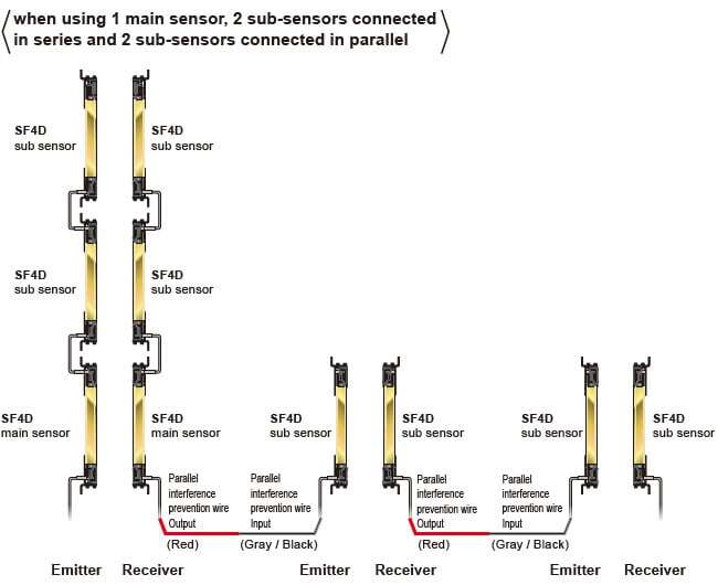
| Interference prevention function | <Not connected in series/parallel> ・Line synchronization: 2 units or less (auto) ・Optical synchronization: 2 units or less (selectable by DIP switch) <Connected in series/parallel> ・Series connection: 5 units or less (total number of beam channels 256 or less) ・Parallel connection: 3 units or less (total number of beam channels 192 or less) (Note 6) ・Series / parallel connection mixed: 5 units or less (total number of beam channels 144 or less) (Note 6) | |||
| Test input function | Incorporated | |||
| Interlock function | Incorporated [Manual reset / auto reset (selectable by wiring)] (8-core cable or 12-core cable) | |||
| Lockout release function | Incorporated | |||
| External device monitor function | Incorporated (8-core cable or 12-core cable) | |||
| Application indicator function | Incorporated (only the receiver lights up when optical synchronization is used) | |||
| Muting function | Incorporated (12-core cable) | |||
| Override function | Incorporated (12-core cable) | |||
| Power save function | Incorporated | |||
| Optional functions (Note 10) (Excluding SF4D-□-01) | Fixed blanking function, floating blanking function, interlock setting function, external device monitoring setting function, auxiliary output setting function, application indicator setting function, muting setting function, override setting function, protect function, I/O setting function | |||
| Pollution degree | 3 | |||
| Operating altitude | 2,000 m 6,561.68 ft or less (Note 11) | |||
| Environmental resistance | Degree of protection | IP67, IP65 (IEC), NEMA Type 13 (NEMA 250) | ||
| Ambient temperature | -10 to +55 ℃ +14 to +131 ℉ (No dew condensation or icing allowed), Storage: -25 to +60 ℃ -13 to +140 ℉ | |||
| Ambient humidity | 30 to 85 % RH, Storage: 30 to 95 % RH | |||
| Ambient illumination | Incandescent light: 5,000 ℓx or less at the light-receiving surface | |||
| Dielectric strength voltage | 1,000 V AC for one minute, between all supply terminals connected together and enclosure | |||
| Insulation resistance | 20 MΩ, or more, with 500 V DC megger, between all supply terminals connected together and enclosure | |||
| Vibration resistance | 10 to 55 Hz, 0.75 mm 0.030 in double amplitude in X, Y, and Z directions for two hours each Malfunction resistance 10 to 55 Hz, 0.75 mm 0.030 in double amplitude in X, Y, and Z directions twenty times each | |||
| Shock resistance | 300 m/s2 acceleration (30 G approx.) in X, Y, and Z directions three times each Malfunction resistance 100 m/s2 acceleration (10 G approx.) in X, Y, and Z directions 1,000 times each | |||
| SFF (Safe Failure Fraction) | 99% | |||
| HFT (Hardware Fault Tolerance) | 1 | |||
| Subsystem type | Type B (IEC 61508-2) | |||
| T1 (proof test interval) | 20 years | |||
| Failure response time | Within response time (OFF response) | |||
| Safety state | Control output (OSSD 1 / 2) OFF state | |||
| Emitter element | Infrared LED (peak emission wavelength: 850 nm 0.034 mil) | |||
| Material | Enclosure: Aluminum, Detection surface: Polycarbonate resin and stainless steel (SUS304), Upper cap / lower cap: Nylon | |||
| Connecting method | By connector | |||
| Cable extension | Total length of emitter / receiver can be extended up to 70 m 229.659 ft each using optional mating cable (including the length of cables for series connection) (Note 5) | |||
Notes:
1) Where measurement conditions have not been specified precisely, the conditions used were an ambient temperature of +20 ℃ +68 ℉.
2) Except for SF4D-□-01, Korea KCs mark is acquired.
3) The operating range is the possible setting distance between the emitter and the receiver.
4) When the floating blanking function is used, the size of the minimum sensing object varies. For the detail, refer to the section on Safety distance.
5) The power supply unit must satisfy the following requirements:
1) The power unit must be certified for use in your region.
2) Use of the product as a unit in compliance with CE Marking: SELV (safety extra low voltage) / PELV (protected extra low voltage) power supply unit in conformity with EMC Directive and Low Voltage Directive.
3) Use of the product as a unit in compliance with UKCA Marking: SELV (safety extra low voltage) / PELV (protected extra low voltage) power supply unit in conformity with EMC Regulations and Low Voltage Regulations.
4) When using a commercial switching regulator, the frame ground (F.G.) terminal must be connected to ground.
5) The power supply unit must have an output holding time of 20ms or more.
6) If surges occur, take countermeasures such as connecting a surge absorber to the source of the surges.
7) The power unit must be a CLASS 2 compliant unit. (When CTÜVUS mark compliance is required.)
6) In consideration of the voltage drop caused by the cable, use Control output (OSSD 1, OSSD 2) source / sink current and cable length as a guidebrline.
7) The setting can be changed when the SF4D-TM1 (optional) and Configurator Light Curtain setting software are used. Note that the setting cannot be changed when SF4D-□-01 is used.
8) For response times by number of beams, refer to the Control output (OSSD 1, OSSD 2) OFF response times.
9) Because the control output (OSSD 1, OSSD 2) must be OFF for at least 80 ms, the ON response will be delayed more than 50 ms when the light blocked time is less than 30 ms.
10) When optical synchronization is selected, if the beam axes of both the top end and bottom end are blocked, the ON response speed decreases by as much as 1 sec.
11) To use optional functions, the SF4D-TM1 (optional) and Configurator Safety Light Curtain setting software are required. Note that optional functions cannot be used when SF4D-□-01 is used.
12) Do not use or store in an environment pressurized to atmospheric pressure or higher at an altitude of 0 m.
Control output (OSSD 1, OSSD 2) source / sink current and cable length
| Number of sub-sensors | Control output (OSSD 1, OSSD 2) source / sink current | Power supply cable length Length of cable for series connection (Total cable length) | Cable | |
|---|---|---|---|---|
| Power supply cable length | Cable length for series connection | |||
| 0 (No series connection) | 100 mA | 70 m 229.659 ft or less | - | - |
| 200 mA | ||||
| 350 mA | 10.5 m 34.449 ft or less | |||
| 1 | 100 mA | 50 m 164.042 ft or less | - | Cable length obtained by subtracting power supply cable length from total cable length |
| 200 mA | ||||
| 350 mA | 10.5 m 34.449 ft or less | |||
| 2 | 100 mA | 50 m 164.042 ft or less | - | |
| 200 mA | ||||
| 350 mA | 10.5 m 34.449 ft or less | |||
| 3 | 100 mA | 50 m 164.042 ft or less | - | |
| 200 mA | 40.5 m 132.874 ft or less | |||
| 350 mA | 10.5 m 34.449 ft or less | |||
| 4 | 100 mA | 25.5 m 83.661 ft or less | - | |
| 200 mA | 20.5 m 67.257 ft or less | |||
| 350 mA | 10.5 m 34.449 ft or less | |||
* Power supply cable: Cable consisting of the bottom cap cable (optional) and extension cable (optional)
Control output (OSSD 1, OSSD 2) OFF response times
| OFF response time | |||||||||||||
|---|---|---|---|---|---|---|---|---|---|---|---|---|---|
| Main sensor | Sub sensor | ||||||||||||
| Number of units connected in series | 1 unit | 1 unit | 2 units | 3 units | 4 units | 0 unit | 0 unit | 1 unit | 1 unit | 2 units | 2 units | 3 units | |
| Number of units connected in parallel | 0 unit | 0 unit | 0 unit | 0 unit | 1 unit | 2 units | 1 unit | 2 units | 1 unit | 2 units | 1 unit | ||
| Total number of beams | 4 to 48 | 6ms | 10ms | 10ms | 12ms | 12ms | 14ms | 14ms | 14ms | 14ms | 14ms | 14ms | 14ms |
| 49 to 96 | 8ms | 10ms | 10ms | 12ms | 12ms | 14ms | 14ms | 14ms | 14ms | 14ms | 14ms | 14ms | |
| 97 to 127 | 10ms | 12ms | 12ms | 14ms | 14ms | 14ms | 14ms | 14ms | 14ms | 14ms | 14ms | 14ms | |
| 128 to 144 | - | 12ms | 12ms | 14ms | 14ms | 14ms | 14ms | 14ms | 14ms | 14ms | 14ms | 14ms | |
| 145 to 192 | - | 14ms | 14ms | 16ms | 16ms | 14ms | 14ms | - | - | - | - | - | |
| 193 to 256 | - | 16ms | 16ms | 18ms | 18ms | - | - | - | - | - | - | - | |
・Example of series connection
5 units or fewer (Total number of beam channels must be 256 or less.)
・Example of combination of series connection and parallel connection
5 units or fewer (Total number of beam channels must be 144 or less.)
Note: Refer to the manual on our website for details
Control units
For specifications of the control units, please see each product page.
>>"Safety Control Unit SF-C21"
>>"Exclusive Control Unit for Safety Light Curtain SF-C10"
IO-Link communication unit
| Product name | IO-Link communication unit for safety light curtain SF4D series | |
|---|---|---|
| Model No. | SFD-WL3 | |
| Applicable regulations | CE Marking (EMC Directive, RoHS Directive), UKCA Marking (EMC Regulations, RoHS Regulations) | |
| Communication method | Safety light curtain communication side | RS-485 bidirectional communication (dedicated protocol) |
| IO-Link communication side | IO-Link specifications: Ver. 1.1 | |
| Baud rate: COM3 (230.4 kbps) | ||
| Data length: 18 bytes, process data (PD) | ||
| Minimum cycle time: 1.5 ms | ||
| Supply voltage | Safety light curtain communication side | 24V DC +20-30 % Ripple P-P 10 % or less |
| IO-Link communication side | 24V DC +20-25 % Ripple P-P 10 % or less | |
| Current consumption | Safety light curtain communication side | 15 mA or less |
| IO-Link communication side | 30 mA or less | |
| Functions | • IO-Link communication function • Safety light curtain setting data copy function (Note 2, 3, 4) | |
| Number of connectable units | This product | 1 unit |
| Safety light curtains in series connection | Up to 5 units (total number of beam channels 256 or less) | |
| Pollution degree / Excess voltage category | 3 / I | |
| Operating altitude | 2,000 m 6561.68 ft or less (Note 5) | |
| Environmental resistance | Protection | IP64 (IEC) |
| Ambient temperature | -10 to +55℃ 14 to 131℉ (No dew condensation or icing allowed), Storage: -25 to +60℃ -13 to 140℉ | |
| Ambient humidity | 30 to 85% RH, Storage: 30 to 95% RH | |
| Dielectric strength voltage | 1,000 V AC for one min. between all supply terminals connected together and enclosure | |
| Insulation resistance | 20 MΩ, or more, with 500 V DC megger, between all supply terminals connected together and enclosure | |
| Vibration resistance | 10 to 55 Hz, 0.75 mm 0.030 in double amplitude in X, Y, and Z directions for two hours each Malfunction resistance 10 to 55 Hz, 0.75 mm 0.030 in double amplitude in X, Y, and Z directions twenty times each | |
| Shock resistance | 300 m/s2 acceleration (30 G approx.) in X, Y, and Z directions three times each Malfunction resistance 100 m/s2 acceleration (10 G approx.) in X, Y, and Z directions 1,000 times each | |
| Material | Main unit case: PA66 (with glass) Base plate: SPCC + Plating Product model nameplate: Polyester External connection connector: Brass + Plating | |
| Connection method | Safety light curtain communication side | 8-core cable for safety light curtain (optional) |
| IO-Link communication side | 4-core cable with M12 connector (commercially available product) | |
| Weight | Net weight: 270 g approx., Gross weight: 340 kg approx. | |
Communication module
| Model No. | SF4D-TM1 |
|---|---|
| Communication system | Safety light curtain side: RS-485 bilateral communication (dedicated protocol) PC side: USB |
| Connection system | Safety light curtain side: Connector PC side: USB (Mini-B male) |
| Protection | IP40 (IEC) |
| Ambient temperature | -10 to +55 ℃ +14 to +131 ℉ (no dew condensation or icing allowed), Storage: -25 to +60 ℃ -13 to +140 ℉ |
| Ambient humidity | 30 to 85% RH, Storage: 30 to 95% RH |
| Usable altitude | 2,000 m 6,561.68 ft or lower (Note 2) |
| Cable | 1.5 m 4.921 ft cable with connector (safety light curtain side) (Note 3) |
| Weight | Net weight: 75 g approx. |
Laser alignment tool
| Model No. | SF-LAT-2N |
|---|---|
| Supply voltage | 3 V (LR6 battery x 2 pcs.) |
| Battery | 1.5 V (LR6 battery) x 2 pcs. (replaceable)(Note 2) |
| Battery lifetime | 30 hours approx. of continuous operation (LR6 battery, at +25 ℃ +77 ℉ ambient temperature) |
| Light source | Red semiconductor laser: class 2 (IEC / JIS), Class II (FDA) (Max. output: 1 mW, Peak emission wavelength: 650 nm 0.026 mil)(Note 3) |
| Spot diameter | 10 mm 0.394 in approx. (at 5 m 16.404 ft distance) |
| Ambient temperature | 0 to +40 ℃ +32 to +104 ℉ (No dew condensation), Storage: 0 to +55 ℃ +32 to +131 ℉ |
| Ambient humidity | 35 to 85 % RH, Storage: 35 to 85 % RH |
| Material | Enclosure: ABS, Mounting part: Aluminum |
| Weight | Net weight: 150 g approx. (without batteries) |
Notes:
1) Where measurement conditions have not been specified precisely, the conditions used were an ambient temperature of +20 ℃ +68 ℉.
2) LR6 dry cell batteries are not provided with the product. Please purchase them separately.
3) This product complies with the FDA regulations (FDA 21 CFR 1040.10 and 1040.11) in accordance with FDA Laser Notice No. 56, except for complying with IEC 60825-1 Ed. 3.
Corner mirror
| Model No. | RF-SFBH-□ | |
|---|---|---|
| Attenuation rate of operating range | With one corner mirror: Declined to 90 %, With two corner mirrors: Declined to 80 %, With three corner mirrors: Declined to 70 % (When used in combination with the SF4D series) | |
| Environmental resistance | Ambient temperature | –10 to +55 ℃ +14 to +131 ℉ (No dew condensation or icing allowed), Storage: –25 to +70 ℃ –13 to +158 ℉ |
| Ambient humidity | 30 to 85 % RH, Storage: 30 to 95 % RH | |
| Vibration resistance | 10 to 55 Hz frequency, 0.75 mm 0.030 in double amplitude in X, Y and Z directions for two hours each | |
| Shock resistance | 300 m/s2 acceleration (30 G approx.) in X, Y and Z directions three times each | |
| Material | Enclosure: Aluminum, Mounting bracket: Stainless steel, Mirror (rear surface mirror): Glass, Side cover: EPDM | |
| Accessories | Intermediate supporting bracket: 1 set (RF-SFBH-40/48/56/64), 2 sets (RF-SFBH-72/80/88/96) | |
Notes:
1)Where measurement conditions have not been specified precisely, the conditions used were an ambient temperature of +20 ℃ +68 ℉.
2)The corner mirror has not received type examination by the Ministry of Health, Labour and Welfare; therefore, it cannot be used for presses or shearing machines (paper cutting machines) in Japan.
SF4D conversion adapter
| Item | SFD-J4B (For 8-core cable) SFD-J4B-MU (For 12-core cable) | |
|---|---|---|
| Environmental resistance | Protection | IP64 (IEC) |
| Ambient temperature | -10 to +55 ℃ +14 to +131 ℉ (No dew condensation or icing allowed), Storage: -25 to +60 ℃ -13 to +140 ℉ | |
| Ambient humidity | 30 to 85% RH, Storage: 30 to 95% RH | |
| Dielectric strength voltage | 1,000 V AC for one min. between all supply terminals connected together and enclosure | |
| Insulation resistance | 20 MΩ, or more, with 500 V DC megger, between all supply terminals connected together and enclosure | |
| Vibration resistance | 10 to 55 Hz, 0.75 mm 0.030 in double amplitude in X, Y, and Z directions for two hours each Malfunction resistance 10 to 55 Hz, 0.75 mm 0.030 in double amplitude in X, Y, and Z directions twenty times each | |
| Shock resistance | 300 m/s2 acceleration (30 G approx.) in X, Y, and Z directions three times each Malfunction resistance 100 m/s2 acceleration (10 G approx.) in X, Y, and Z directions 1,000 times each | |
| Material | Enclosure: Nylon, Mounting part: Cold rolled carbon steel (SPCC) | |
| Weight | Net weight: 270 g approx. , Gross weight: 300 g approx. | |
Note: Where measurement conditions have not been specified precisely, the conditions used were an ambient temperature of +20 ℃ +68 ℉.
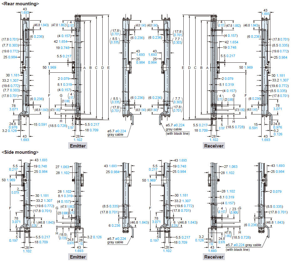
Dimensions
- Unit: mm in
Safety light curtain Assembly dimensions
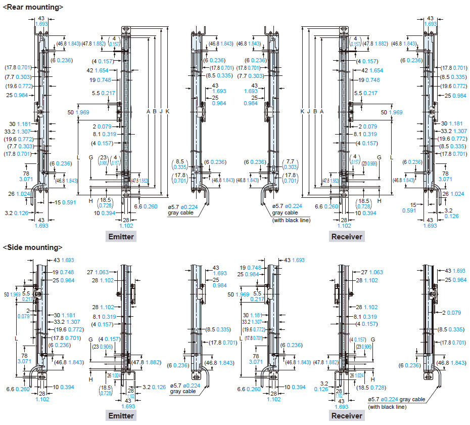
- Mounting drawing for the safety light curtains using the beam adjustment mounting bracket MS-SFD-1-5 (optional) and the intermediate support brackets MS-SFB-2 (optional).
- Mounting drawing for the safety light curtains using the beam adjustment mounting bracket MS-SFD-1-6 (optional) and the intermediate support brackets MS-SFB-2 (optional).
- Mounting drawing for the safety light curtains using the beam adjustment mounting bracket MS-SFD-1-8 (optional) and the intermediate support brackets MS-SFB-2 (optional).
- Mounting drawing for the safety light curtains using the dead zoneless beam adjustment mounting bracket MS-SFD-3-6 (optional)
- Mounting drawing for safety light curtains using the SF4B-G compatible mounting bracket MS-SFD-4BG (optional) and the intermediate support bracket MS-SFB-2.
Options
SF4D-□(-01)
Safety light curtain
Assembly dimensions
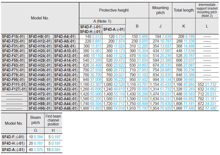
Mounting drawing for the safety light curtains using the beam adjustment mounting bracket MS-SFD-1-5 (optional) and the intermediate support brackets MS-SFB-2 (optional).
Notes:
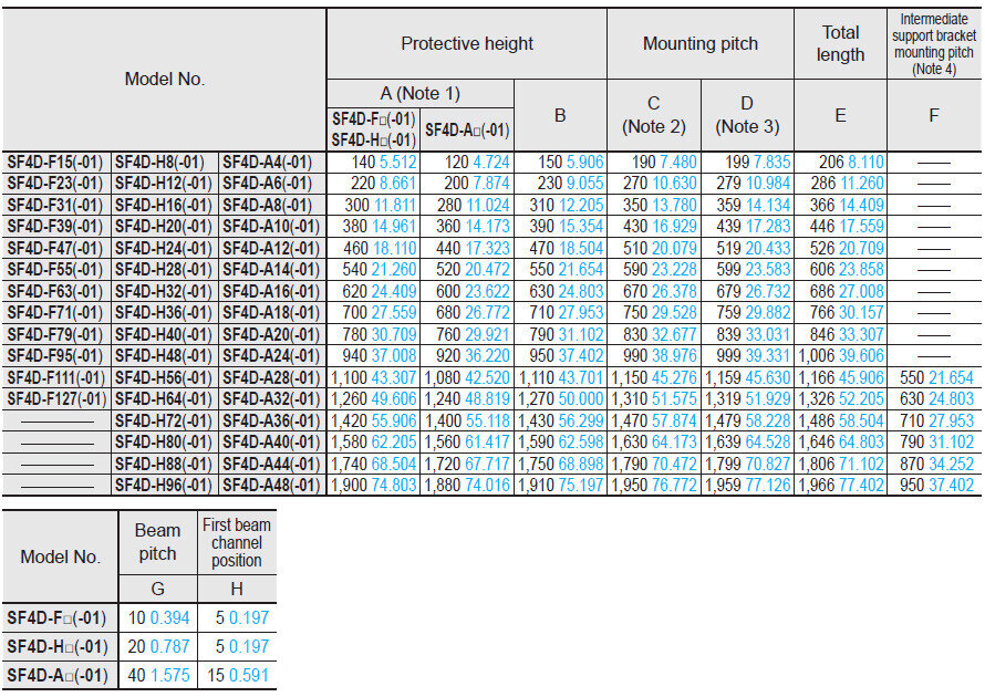
1) In the case of "When used as safety device for presses in China" or "When SF4D-□-01 is used for presses or shearing machines (paper cutting machines) in Japan," the distance between the center of the first beam axis and the center of the last beam axis of the device becomes the protective height (A).
2) Mounting pitch when beam adjustment mounting bracket MS-SFD-1-5 (optional) is mounted with two M5 hexagon-socket head bolts.
3) Mounting pitch when beam adjustment mounting bracket MS-SFD-1-5 (optional) is mounted with one M8 hexagon-socket head bolt.
4) When the number of beam channels is SF4D-F□(-01): 111 or more beam channels, SF4D-H□(-01): 56 or more beam channels, SF4D-A□(-01): 28 or more beam channels, one set is required.
Assembly dimensions
Mounting drawing for the safety light curtains using the beam adjustment mounting bracket MS-SFD-1-6 (optional) and the intermediate support brackets MS-SFB-2 (optional).
Notes:
1) In the case of "When used as safety device for presses in China" or "When SF4D-□-01 is used for presses or shearing machines (paper cutting machines) in Japan," the distance between the center of the first beam axis and the center of the last beam axis of the device becomes the protective height (A).
2) When the number of beam channels is SF4D-F□(-01): 111 or more beam channels, SF4D-H□(-01): 56 or more beam channels, SF4D-A□(-01): 28 or more beam channels, one set is required.
Assembly dimensions
Mounting drawing for the safety light curtains using the beam adjustment mounting bracket MS-SFD-1-8 (optional) and the intermediate support brackets MS-SFB-2 (optional).
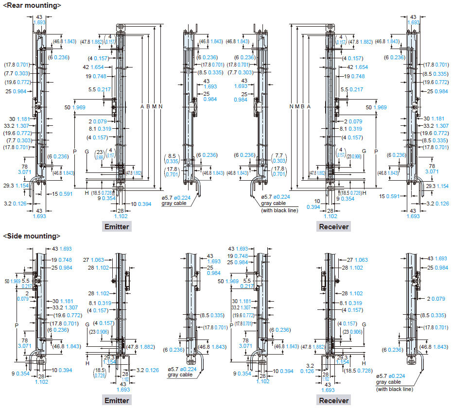
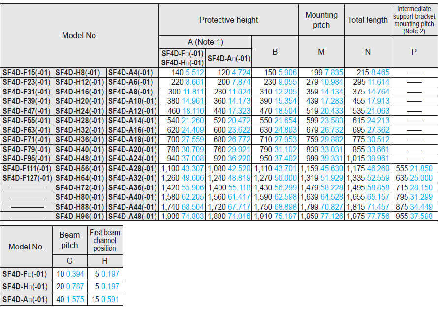
Notes:
1) In the case of "When used as safety device for presses in China" or "When SF4D-□-01 is used for presses or shearing machines (paper cutting machines) in Japan," the distance between the center of the first beam axis and the center of the last beam axis of the device becomes the protective height (A).
2) When the number of beam channels is SF4D-F□(-01): 111 or more beam channels, SF4D-H□(-01): 56 or more beam channels, SF4D-A□(-01): 28 or more beam channels, one set is required.
Assembly dimensions
Mounting drawing for the safety light curtains using the dead zoneless beam adjustment mounting bracket MS-SFD-3-6 (optional)
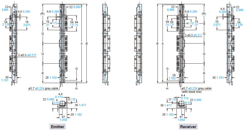
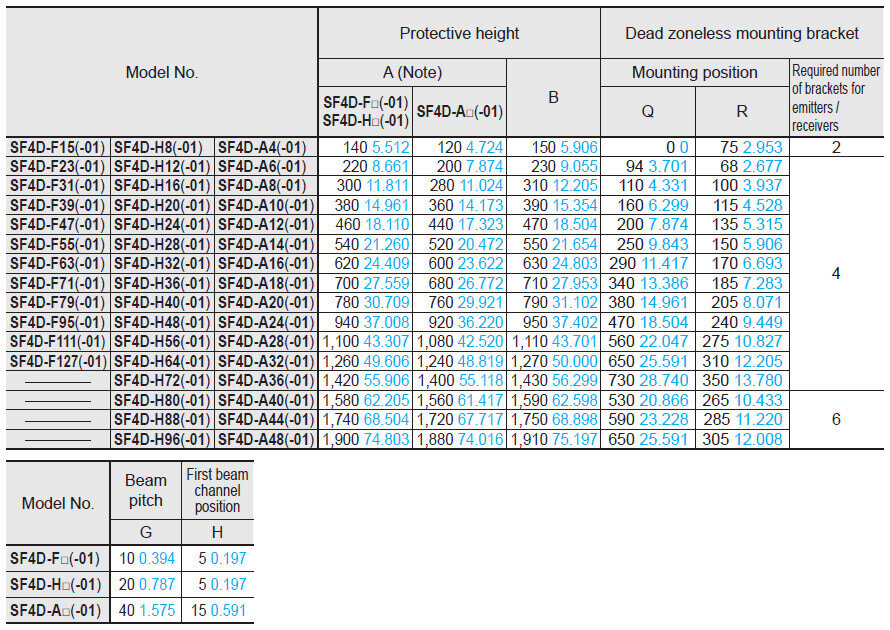
Note: In the case of "When used as safety device for presses in China" or "When SF4D-□-01 is used for presses or shearing machines (paper cutting machines) in Japan," the distance between the center of the first beam axis and the center of the last beam axis of the device becomes the protective height (A).
Assembly dimensions
Mounting drawing for safety light curtains using the SF4B-G compatible mounting bracket MS-SFD-4BG (optional) and the intermediate support bracket MS-SFB-2.
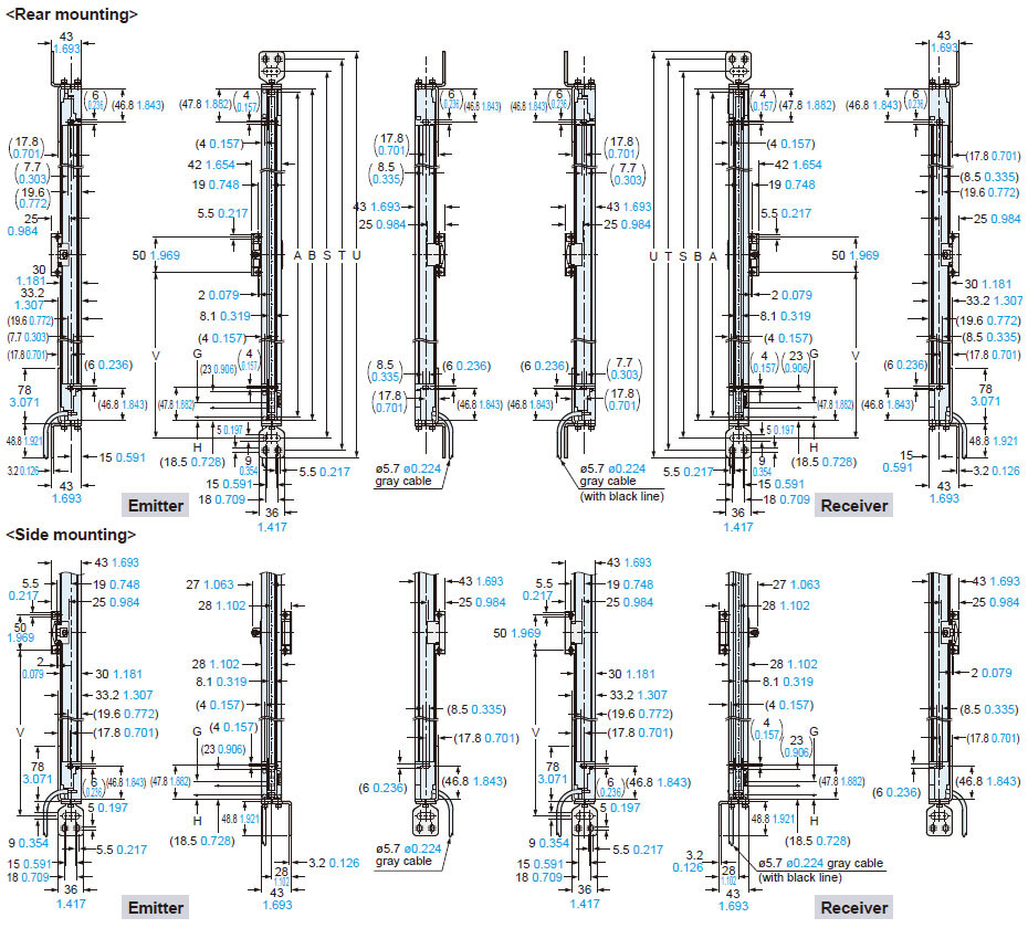
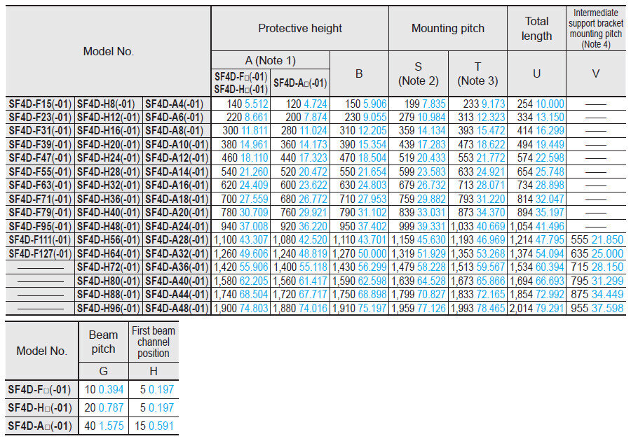
Notes:
1) In the case of "When used as safety device for presses in China" or "When SF4D-□-01 is used for presses or shearing machines (paper cutting machines) in Japan," the distance between the center of the first beam axis and the center of the last beam axis of the device becomes the protective height (A).
2) Mounting pitch when the SF4B-G compatible mounting bracket MS-SFD-4BG (optional) is installed using one M8 hexagon socket head bolt.
3) Mounting pitch when the SF4B-G compatible mounting bracket MS-SFD-4BG (optional) is installed using two M5 hexagon socket head bolts.
4) When the number of beam channels is SF4D-F□(-01): 111 or more beam channels, SF4D-H□(-01): 56 or more beam channels, SF4D-A□(-01): 28 or more beam channels, one set is required.
MS-SFD-1-5
Beam adjustment mounting bracket (Optional)
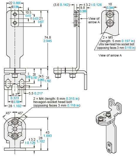
4 pcs./set for emitter and receiver
Material: Cold rolled carbon steel (SPCC)
MS-SFD-1-6
Beam adjustment mounting bracket (Optional)
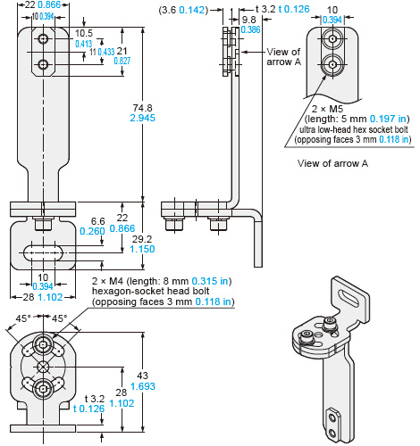
4 pcs./set for emitter and receiver
Material: Cold rolled carbon steel (SPCC)
MS-SFD-1-8
Beam adjustment mounting bracket (Optional)
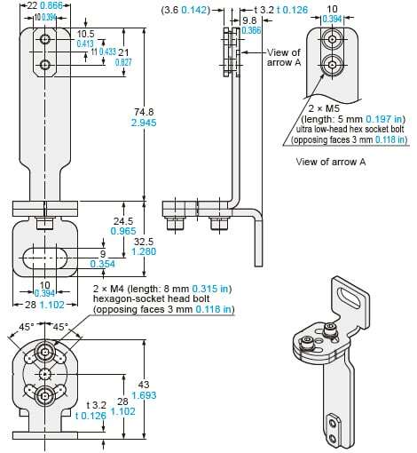
4 pcs./set for emitter and receiver
Material: Cold rolled carbon steel (SPCC)
MS-SFD-3-6
Dead zoneless beam adjustment mounting bracket (Optional)
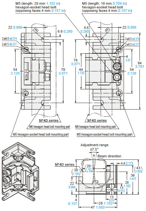
4 pcs./set for emitter and receiver
Material: Die-cast zinc alloy
MS-SFB-2
Intermediate support bracket (Optional)
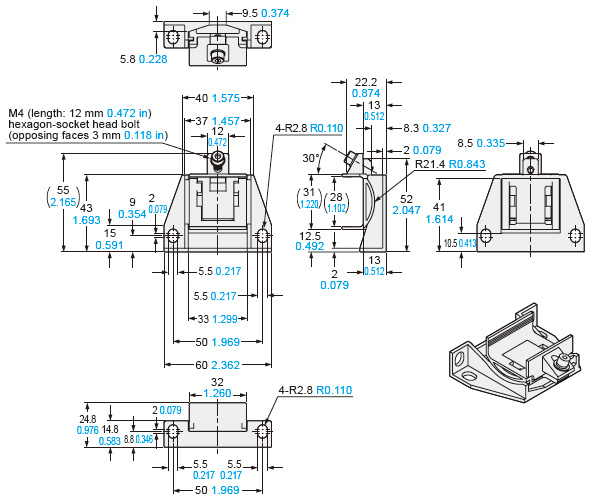
2 pcs./set for emitter and receiver
Material: Die-cast zinc alloy
MS-SFD-4BG
SF4B-G compatible mounting bracket (Optional)
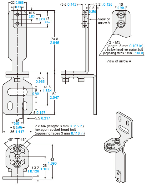
4 pcs./set for emitter and receiver
Material: Cold rolled carbon steel (SPCC)
SF4D-TM1
Communication module (Optional)
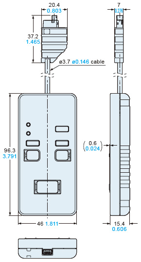
SFD-WL3
IO-Link communication unit (Optional)
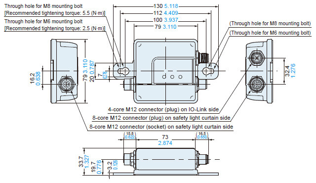
RF-SFBH-□
Corner mirror (Optional)
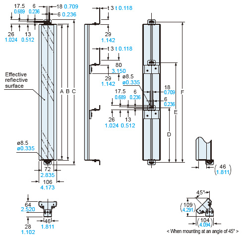
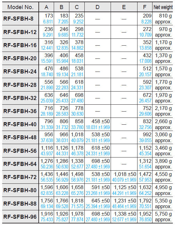
SF-LAT-2N
Laser alignment tool (Optional)
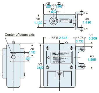
SFB-WY1
Y-shaped connector (Optional)

SFD-J4B
SF4D conversion adapter for 8-core cable (Optional)
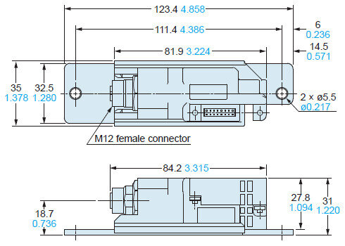
SFD-J4B-MU
SF4D conversion adapter for 12-core cable (Optional)

Software
Setting software
Configurator Light Curtain
The handy controller software, which was well-received by users of our previous models, has evolved. The new setting software, Configurator Safety Light Curtain, allows visually intuitive operation.
It provides powerful support to maintaining stable operation and troubleshooting by allowing the internal setup of the SF4D series product, collection of error history, planning of corrective measures and real-time monitoring of light incidence condition.
Main functions
- Operation monitoring function
(Monitoring of received light intensity / extraneous light of individual beam
I/O monitoring) - Error history display
- Light blockage history, unstable light incidence history
- Muting setting function
- Override setting function
- Blanking setting function
(Fixed blanking setting function
Floating blanking setting function) - External device monitoring setting function
- Auxiliary output setting function
* Note that the usable functions vary depending on the synchronization method (optical synchronization, line synchronization) and the type of cables (5-core, 8-core, 12-core) used.
For details, refer to "Selectable synchronization method and cable to suit various applications" and the manual.
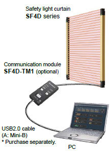


This function is used to set the arrangement of muting sensors and select the most suitable settings using the application. It is also equipped with a time chart function, which obtains actual input timing to facilitate adjustment work.
*Excluding SF4D-□-01


Communication module copy function
When a PC cannot be brought in, the communication module can be used to write the setting data of the safety light curtain and also to read error information.
*Excluding SF4D-□-01
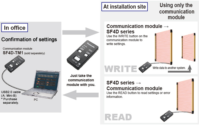
* USB cable is not supplied with the product.
USB2.0 cable (A: Mini-B) must be procured by the user.
Configuration Light Curtain can be downloaded free from our website.
*Membership registration is required to access/download this data.
I/O Circuit and Wiring diagrams
I/O circuit diagram (using optical synchronization setting and 5-core cable, Not connected in series / parallel)
<In case of using I/O circuit for PNP output>
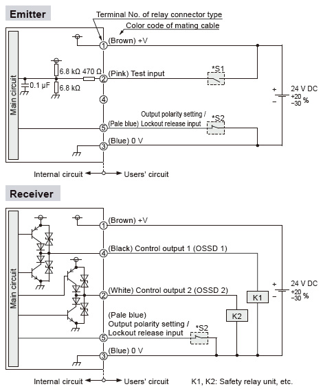
* S1
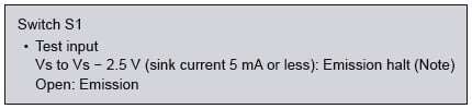
* S2
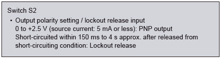
Note: Vs is the applying supply voltage.
<In case of using I/O circuit for NPN output>
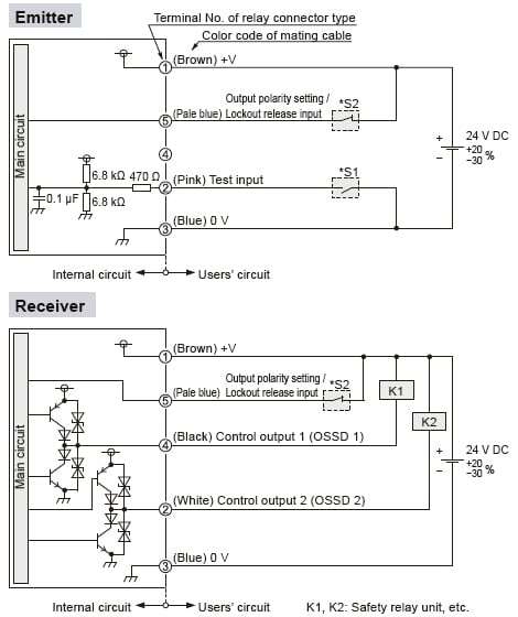
* S1
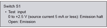
* S2
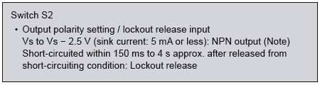
Note: Vs is the applying supply voltage.
I/O circuit diagram (using line synchronization setting and 8-core cable, not connected in series / parallel)
<In case of using I/O circuit for PNP output>
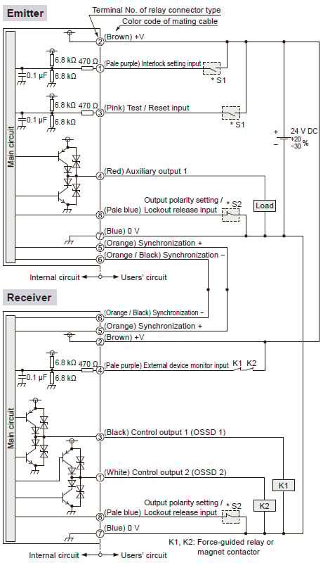
* S1
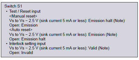
* S2
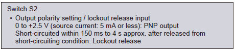
Note: Vs is the applying supply voltage.
<In case of using I/O circuit for NPN output>
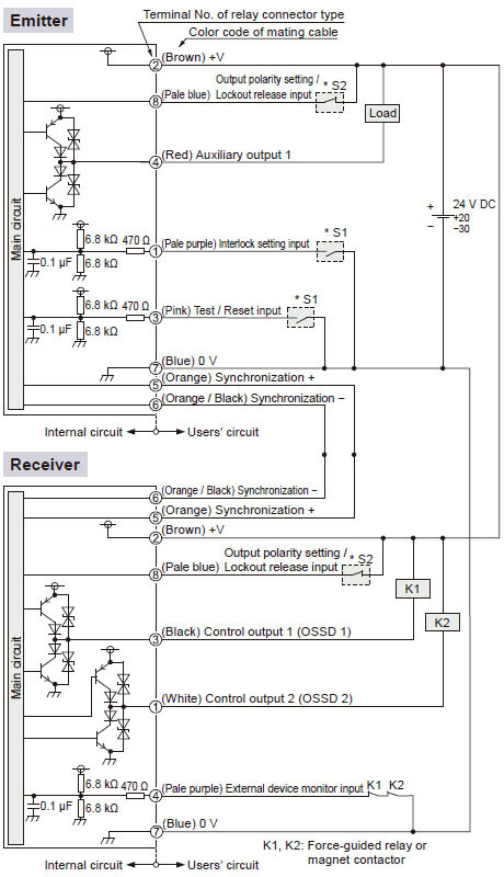
* S1
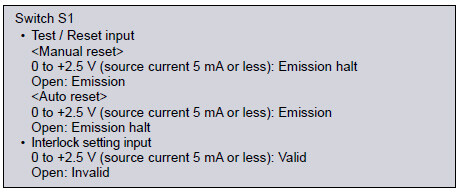
* S2
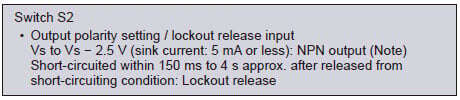
Note: Vs is the applying supply voltage.
I/O circuit diagram (using line synchronization setting and 12-core cable, not connected in series / parallel)
<In case of using I/O circuit for PNP output>
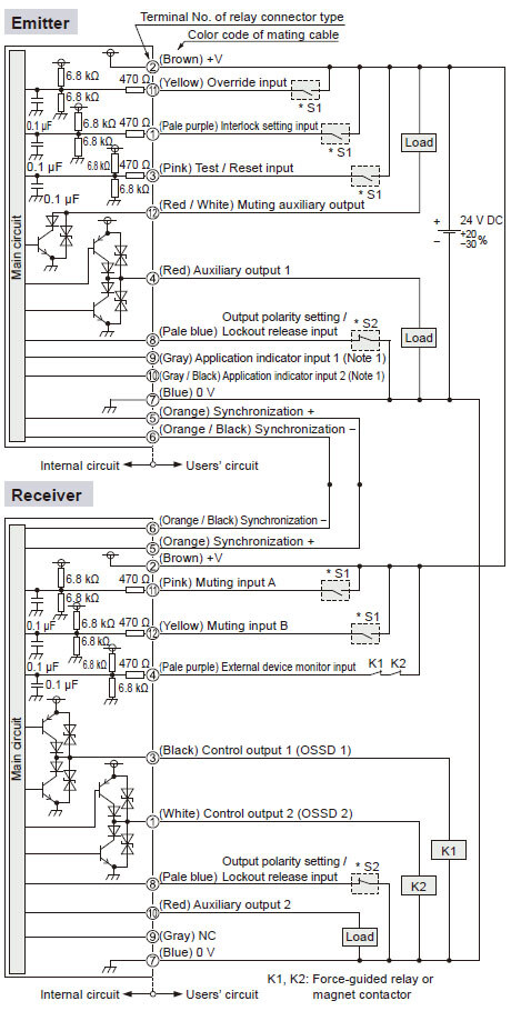
*S1
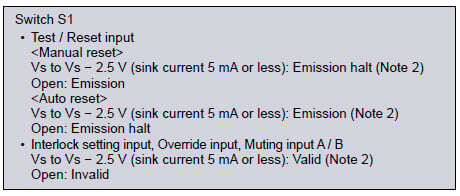
*S2
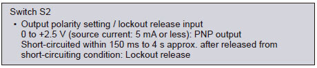
Notes:1) Vs to Vs - 2.5 V (sink current: 5 mA or less): ON (Note 2), Open: OFF2) Vs is the applying supply voltage.
<In case of using I/O circuit for NPN output>
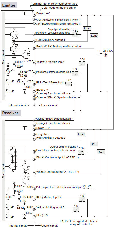
*S1
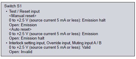
*S2
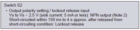
Notes:1) 0 to +2.5 V (sink current: 5 mA or less): ON, Open: OFF2) Vs is the applying supply voltage.
Cautions For Use
Compatibility with communication module SF4D-TM1 for SF4D series
Please note that it doesn't work when connecting the communication module SF4D-TM1 manufactured before November 2019 to Type 4 Compact & Robust Safety Light Curtain SF4D series Ver.3.0 manufactured after March 17, 2020.
Compatibility of SF4D Ver. and SF4D-TM1
| SF4D Ver. 2.0 (manufactured before March 16, 2020) | SF4D Ver. 3.0 (manufactured after March 17, 2020) | |
|---|---|---|
| SF4D-TM1 (manufactured before November 2019) | Yes | No |
| SF4D-TM1 Ver. 2.0 (manufactured after December 2019) | Yes | Yes |
Version identification
■Compact & Robust Safety Light Curtain SF4D Series
| Production lot | manufactured before March 16, 2020 | manufactured after March 17, 2020 |
|---|---|---|
| Version of main body | Ver. 2.0 | Ver. 3.0 |
| Front nameplate | Receiver
| Receiver
|
| Side nameplate | Receiver
| Receiver
|

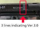
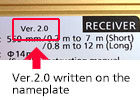

■Communication module SF4D-TM1
| Production lot | manufactured before November 2019 | manufactured after December 2019 |
|---|---|---|
| Version of main body | - | Ver. 2.0 |
| Communication module SF4D-TM1 |
|
|
| Setting software Configurator Light Curtain | Version info. Ver.1.3.0 | Version info. Ver.1.4.0 |
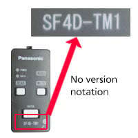
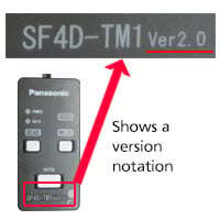
Description and function of each part
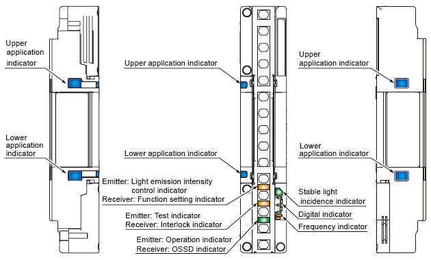
Emitter / receiver common
| Designation | Function | ||||
|---|---|---|---|---|---|
| Line synchronization | Optical synchronization | ||||
| Receiver | Emitter | Receiver | Emitter | ||
| Upper application indicator (Blue / Green / Red / Orange) | When beam axis adjustment mode is set | All beams received [Control output (OSSD 1, OSSD 2) ON]: Lights blue Top beam received: Lights red, Top beam blocked: Turns OFF | Turns OFF | ||
| When application mode is set | When application indicator input 1 is ON: Lights green When application indicator input 2 is ON: Lights red When application indicator input 1 / 2 are ON: Lights orange When application indicator input 1 / 2 are OFF: Turns OFF | Turns OFF | |||
| Lower application indicator (Blue / Green / Red / Orange) | When beam axis adjustment mode is set | All beams received [Control output (OSSD 1, OSSD 2) ON]: Lights blue Bottom beam received: Lights red, Bottom beam blocked: Turns OFF | Turns OFF | ||
| When application mode is set | When application indicator input 1 is ON: Lights green When application indicator input 2 is ON: Lights red When application indicator input 1 / 2 are ON: Lights orange When application indicator input 1 / 2 are OFF: Turns OFF | Turns OFF | |||
| Stable light incidence indicator (Green / Orange) | When light reception is stable: Lights green When light reception is unstable: Lights orange When light is blocked: Turns OFF | Turns OFF | |||
| Digital indicator (Green / Yellow) | Light receiving intensity (Green) | Incident light level 3: Lights green "
Incident light level 2: Lights green "
Incident light level 1: Lights green "
When light is blocked: Turns OFF | Turns OFF | ||
| Error (Yellow) | Normal operation: Turns OFF, Error: Yellow number blinks or lights "
| ||||
| Polarity (Yellow) | When PNP output is set: Lights yellow "
When NPN output is set: Lights yellow "
| ||||
| Frequency indicator (Orange) | - | When frequency 1 is set: Lights orange "
When frequency 2 is set: Lights orange "
| |||


Emitter
| Designation (Note 1) | Function | |
|---|---|---|
| Line synchronization | Optical synchronization | |
| Light emission intensity control indicator (Orange) [CTRL] | Short mode: Turns OFF, Long mode: Lights orange | |
| Test indicator (Orange) [TEST] | During test: Lights orang, Normal operation: Turns OFF | |
| Operation indicator (Green / Red) [OP] | Control output (OSSD 1 / 2) ON: Lights green Control output (OSSD 1 / 2) OFF: Lights red | Normal operation: Lights green Error: Lights red |
Receiver
| Designation (Note 1) | Function | |
|---|---|---|
| Line synchronization | Optical synchronization | |
| Function setting indicator (Orange) [FUNC] | When communication module is connected: Blinks orange, When blanking function or parallel connection is used: Lights orange (Note 2) | |
| Interlock indicator (Yellow) [LOCK] | Interlock activated: Lights yellow, All other times: Turns OFF | |
| OSSD indicator (Green / Red) [OSSD] | Control output (OSSD 1 / 2) ON: Lights green Control output (OSSD 1 / 2) OFF: Lights red | |
Notes:
1) Designations in brackets [ ] are names that are indicated on the device.
2) For the details of blanking function and parallel connection, refer to the instruction manual.
Example of correct sensing area setup
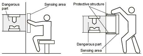
Example of incorrect sensing area setup
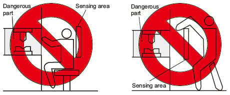
Safety distance