Basic Information
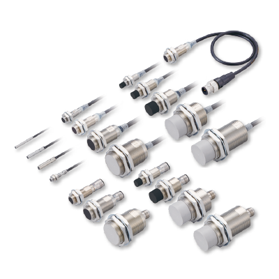
Standard Type Cylindrical Inductive Proximity Sensors with Improved Basic Performance


UL : Excluding small-diameter type
UL : Small-diameter type only. Excluding bending resistant cable type.
Features

Response frequency of 5 kHz* allows the use of high-speed application
* In the case of GX-303S
The GX-303S boasts a response frequency of 5 kHz and realizes high speed response.
The response frequency of other sensor models has been also improved by up to 4 times as compared to our conventional models.
Since the GX-300 series responds quickly to sensor ON/OFF judgement, it works well with a high-speed application and contributes to the reduction of equipment cycle time.

What is response frequency?

A rotating plate having the standard sensing object pasted at constant intervals is placed in front of the proximity sensor. The plate is rotated while observing the sensing output. The maximum number of times per second at which sensing can be done, for which the corresponding sensing output can be obtained, is the maximum response frequency.
In other words, the larger the numeric value of the response frequency is, the faster the response is.
Example) Conversion of response frequency to response speed
1 kHz → 1-ms cycle
5 kHz → 0.2-ms cycle
Enhanced a degree of the detection margin
Sensing over long distance
The M8 / M12 / M18 / M30 threaded type sensors are available in standard sensing range type or long sensing range type ("K" at the end of model No.).
The long sensing range means reliable detection with plenty of performance margin to spare.

Minimum risk of collision or sensing error even if the distance to the sensing object changes due to equipment vibration
If the distance to the sensing object changes due to equipment vibration or time-related degradation, the sensor may generate sensing errors including sensing failure in some cases.
If the sensor is set up very close to the sensing object for the purpose of preventing detecting failures, the sensor may contact the sensing object and cause damage.
The long sensing range models facilitate the sensor setup for reliable sensing since they detect the sensing object at a long distance.

Reduced variation in maximum operation distance
With the GX-300 series, variation in maximum operation distance is kept within ±10%
* ±15% in the case of the previous GX series.
Variation in the maximum operation distance of the ø3 / ø4 / ø5.4 mm ø0.118 / ø0.157 / ø0.213 in, M5 / M8 threaded type models has been also reduced as compared to the conventional models.

Indicator with significantly improved visibility
The indicator is conveniently visible from any direction, thus facilitating installation check and operation confirmation.


* The indicator light may appear differently depending on ambient environments and brightness.
* On the M8 and larger threaded type sensors, the indicator light is visible at 2 locations on one side.
* The operation indicators of the M8 and larger threaded type sensors flash in green during IO-Link communication.

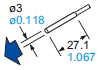
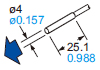
【Comparison of depth dimensions of small-diameter type sensors】
| Type | Our conventional model | GX-300 |
|---|---|---|
| ø3.0mm ø0.118 in | - | 27.1mm 1.067 in |
| ø3.8mm ø0.150 in | 30mm 1.181 in | - |
| ø4.0mm ø0.157 in | - | 25.1mm 0.988 in |
| ø4.4mm ø0.173 in | 30mm 1.181 in | - |
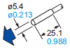
| ø5.4mm ø0.213 in | 30mm 1.181 in | 25.1mm 0.988 in |
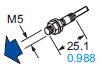
| M5 thread | 30mm 1.181 in Threaded section : 18mm 0.709 in | 25.1mm 0.988 in Threaded section : 15.1mm 0.594 in |

The GX-300 series includes 310 different sensor models.
We offer various types of sensor models such as the cable type (cable length: 2 m 6.562 ft or 5 m 16.404 ft), connector type and pigtailed type. Furthermore, we can supply bending-resistant cable type models (cable length : 2 m 6.562 ft or 5 m 16.404 ft), which are suitable for installation on moving parts.
(For the detail of our model lineup, see page 6 and following pages.)


IO-Link compatibility
Evolution from ON/OFF judgment sensors to sensors capable of transmitting the detection level and sensor status information
* Only the M8 / M12 / M18 / M30 threaded type, PNP output, normally open type models are compatible with IO-Link.
◆ IO-Link compatible sensors can also be used as ordinary sensors (PNP output type).

◆ When IO-Link compatible sensors are connected to the IO-Link master, they can transmit not only ON/OFF signal but also sensor level information and operation mode switching information in both ways. So, the sensors can be utilized for the visualization of manufacturing operations or for the incorporation of IoT technology.

* CC-Link IE Field and CC-Link are trademarks of Mitsubishi Electric Corporation, and are controlled by the CC-Link Partner Association.
DeviceNet and EtherNet/IP are registered trademarks of ODVA (Open DeviceNet Vender Association, Inc.).
EtherCAT is a registered trademark and patented technology, licensed by Beckhoff Automation GmbH in Germany.
Modbus is a registered trademark of Schneider Automation, Inc.

Cautions For Use
Positioning processing equipment

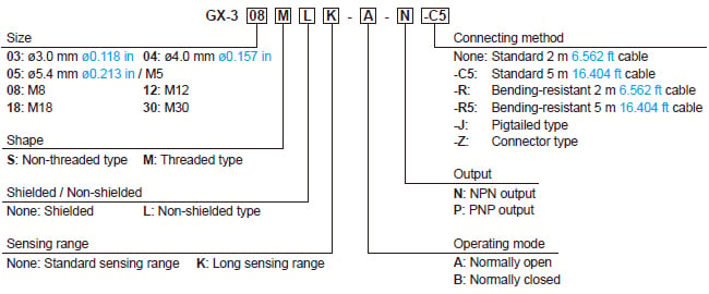
Order guide
Model No.
Small-diameter, shielded type
| Type | Appearance (mm in) | Sensing range (Note) | Model No. | Output | Output operation | |
|---|---|---|---|---|---|---|
| Max. operation distance | Stable sensing range | |||||
| Non-threaded type |
| 0.8mm 0.031 in | 0 to 0.56mm 0 to 0.022 in | GX-303S-A-N | NPN open-collector transistor | Normally open |
| GX-303S-B-N | Normally closed | |||||
| GX-303S-A-P | PNP open-collector transistor | Normally open | ||||
| GX-303S-B-P | Normally closed | |||||
| 1.2mm 0.047 in | 0 to 0.84mm 0 to 0.033 in | GX-304S-A-N | NPN open-collector transistor | Normally open | |
| GX-304S-B-N | Normally closed | |||||
| GX-304S-A-P | PNP open-collector transistor | Normally open | ||||
| GX-304S-B-P | Normally closed | |||||
| 1mm 0.039 in | 0 to 0.7mm 0 to 0.028 in | GX-305S-A-N | NPN open-collector transistor | Normally open | |
| GX-305S-B-N | Normally closed | |||||
| GX-305S-A-P | PNP open-collector transistor | Normally open | ||||
| GX-305S-B-P | Normally closed | |||||
| Threaded type |
| 1.2mm 0.047 in | 0 to 0.84mm 0 to 0.033 in | GX-305M-A-N | NPN open-collector transistor | Normally open |
| GX-305M-B-N | Normally closed | |||||
| GX-305M-A-P | PNP open-collector transistor | Normally open | ||||
| GX-305M-B-P | Normally closed | |||||
Note:
The maximum operation distance stands for the maximum distance for which the sensor can detect the standard sensing object.
The stable sensing range stands for the sensing range for which the sensor can stably detect the standard sensing object even if there is an ambient temperature drift and/or supply voltage fluctuation.
Shielded type
Threaded type
| Type | Appearance (mm in) | Sensing range (Note 1) | Model No. (Note 2) | Output | Output operation | |
|---|---|---|---|---|---|---|
| Max. operation distance | Stable sensing range | |||||
| Standard sensing range type |
| 1.5mm 0.059 in | 0 to 1.2mm 0 to 0.047 in | GX-308M-A-N | NPN open-collector transistor | Normally open |
| GX-308M-B-N | Normally closed | |||||
| GX-308M-A-P | PNP open-collector transistor | Normally open | ||||
| GX-308M-B-P | Normally closed | |||||
| 2mm 0.079 in | 0 to 1.6mm 0 to 0.063 in | GX-312M-A-N | NPN open-collector transistor | Normally open | |
| GX-312M-B-N | Normally closed | |||||
| GX-312M-A-P | PNP open-collector transistor | Normally open | ||||
| GX-312M-B-P | Normally closed | |||||
| 5mm 0.197 in | 0 to 4mm 0 to 0.157 in | GX-318M-A-N | NPN open-collector transistor | Normally open | |
| GX-318M-B-N | Normally closed | |||||
| GX-318M-A-P | PNP open-collector transistor | Normally open | ||||
| GX-318M-B-P | Normally closed | |||||
| 10mm 0.394 in | 0 to 8mm 0 to 0.315 in | GX-330M-A-N | NPN open-collector transistor | Normally open | |
| GX-330M-B-N | Normally closed | |||||
| GX-330M-A-P | PNP open-collector transistor | Normally open | ||||
| GX-330M-B-P | Normally closed | |||||
| Long sensing range type |
| 2mm 0.079 in | 0 to 1.6mm 0 to 0.063 in | GX-308MK-A-N | NPN open-collector transistor | Normally open |
| GX-308MK-B-N | Normally closed | |||||
| GX-308MK-A-P | PNP open-collector transistor | Normally open | ||||
| GX-308MK-B-P | Normally closed | |||||
| 4mm 0.157 in | 0 to 3.2mm 0 to 0.126 in | GX-312MK-A-N | NPN open-collector transistor | Normally open | |
| GX-312MK-B-N | Normally closed | |||||
| GX-312MK-A-P | PNP open-collector transistor | Normally open | ||||
| GX-312MK-B-P | Normally closed | |||||
| 8mm 0.315 in | 0 to 6.4mm 0 to 0.252 in | GX-318MK-A-N | NPN open-collector transistor | Normally open | |
| GX-318MK-B-N | Normally closed | |||||
| GX-318MK-A-P | PNP open-collector transistor | Normally open | ||||
| GX-318MK-B-P | Normally closed | |||||
| 15mm 0.591 in | 0 to 12mm 0 to 0.472 in | GX-330MK-A-N | NPN open-collector transistor | Normally open | |
| GX-330MK-B-N | Normally closed | |||||
| GX-330MK-A-P | PNP open-collector transistor | Normally open | ||||
| GX-330MK-B-P | Normally closed | |||||
Notes:
1) The maximum operation distance stands for the maximum distance for which the sensor can detect the standard sensing object.
The stable sensing range stands for the sensing range for which the sensor can stably detect the standard sensing object even if there is an ambient temperature drift and/or supply voltage fluctuation.
2) The PNP output, normally open type models [GX-3□M(K)-A-P(-□)] are compatible with IO-Link.
The PNP output, normally closed type models and all NPN output type models do not support IO-Link.
Non-shielded type
Threaded type
| Type | Appearance (mm in) | Sensing range (Note 1) | Model No. (Note 2) | Output | Output operation | |
|---|---|---|---|---|---|---|
| Max. operation distance | Stable sensing range | |||||
| Standard sensing range type |
| 2mm 0.079 in | 0 to 1.6mm 0 to 0.063 in | GX-308ML-A-N | NPN open-collector transistor | Normally open |
| GX-308ML-B-N | Normally closed | |||||
| GX-308ML-A-P | PNP open-collector transistor | Normally open | ||||
| GX-308ML-B-P | Normally closed | |||||
| 5mm 0.197 in | 0 to 4mm 0 to 0.157 in | GX-312ML-A-N | NPN open-collector transistor | Normally open | |
| GX-312ML-B-N | Normally closed | |||||
| GX-312ML-A-P | PNP open-collector transistor | Normally open | ||||
| GX-312ML-B-P | Normally closed | |||||
| 10mm 0.394 in | 0 to 8mm 0 to 0.315 in | GX-318ML-A-N | NPN open-collector transistor | Normally open | |
| GX-318ML-B-N | Normally closed | |||||
| GX-318ML-A-P | PNP open-collector transistor | Normally open | ||||
| GX-318ML-B-P | Normally closed | |||||
| 18mm 0.709 in | 0 to 14.4mm 0 to 0.567 in | GX-330ML-A-N | NPN open-collector transistor | Normally open | |
| GX-330ML-B-N | Normally closed | |||||
| GX-330ML-A-P | PNP open-collector transistor | Normally open | ||||
| GX-330ML-B-P | Normally closed | |||||
| Long sensing range type |
| 4mm 0.157 in | 0 to 3.2mm 0 to 0.126 in | GX-308MLK-A-N | NPN open-collector transistor | Normally open |
| GX-308MLK-B-N | Normally closed | |||||
| GX-308MLK-A-P | PNP open-collector transistor | Normally open | ||||
| GX-308MLK-B-P | Normally closed | |||||
| 8mm 0.315 in | 0 to 6.4mm 0 to 0.252 in | GX-312MLK-A-N | NPN open-collector transistor | Normally open | |
| GX-312MLK-B-N | Normally closed | |||||
| GX-312MLK-A-P | PNP open-collector transistor | Normally open | ||||
| GX-312MLK-B-P | Normally closed | |||||
| 16mm 0.630 in | 0 to 12.8mm 0 to 0.504 in | GX-318MLK-A-N | NPN open-collector transistor | Normally open | |
| GX-318MLK-B-N | Normally closed | |||||
| GX-318MLK-A-P | PNP open-collector transistor | Normally open | ||||
| GX-318MLK-B-P | Normally closed | |||||
| 30mm 1.181 in | 0 to 24mm 0 to 0.945 in | GX-330MLK-A-N | NPN open-collector transistor | Normally open | |
| GX-330MLK-B-N | Normally closed | |||||
| GX-330MLK-A-P | PNP open-collector transistor | Normally open | ||||
| GX-330MLK-B-P | Normally closed | |||||
Notes :
1) The maximum operation distance stands for the maximum distance for which the sensor can detect the standard sensing object.
The stable sensing range stands for the sensing range for which the sensor can stably detect the standard sensing object even if there is an ambient temperature drift and/or supply voltage fluctuation.
2) The PNP output, normally open type models [GX-3□ML(K)-A-P(-□)] are compatible with IO-Link.
The PNP output, normally closed type models and all NPN output type models do not support IO-Link.
5 m 16.404 ft cable length type
5 m 16.404 ft cable length type (standard: 2 m 6.562 ft) is also available. When ordering this type, suffix "-C5" to the model No.
(e.g.) 5 m 16.404 ft cable length type of GX-303S-A-N is "GX-303S-A-N-C5".
Bending-resistant cable type (2 m 6.562 ft / 5 m 16.404 ft cable length)
The shielded, non-threaded type sensors (ø4 mm ø0.157 in / ø5.4 mm ø0.213 in) and threaded type sensors (M5 / M8) are available with a bending-resistant cable (cable length: 2 m 6.562 ft or 5 m 16.404 ft). (Note that the ø5.4 mm ø0.213 in size, normally closed type sensors are not available with a 5-m-long bending-resistant cable.)
When ordering bending-resistant 2 m 6.562 ft cable type, suffix "-R" to the model No. When ordering bending-resistant 5 m 16.404 ft cable type, suffix "-R5" to the model No.
(e.g.) Bending-resistant 2 m 6.562 ft cable type of GX-304S-A-N is "GX-304S-A-N-R".
(e.g.) Bending-resistant 5 m 16.404 ft cable type of GX-304S-A-N is "GX-304S-A-N-R5".
Pigtailed type
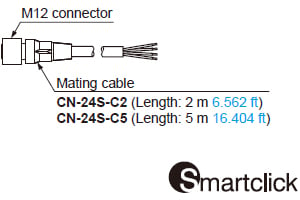
The threaded type sensors (M8 / M12 / M18 / M30) are available in the pigtailed type. (Connector: M12)
When ordering this type, suffix "-J" to the model No.
(e.g.) Pigtailed type of GX-308M-A-N is "GX-308M-A-N-J".
Please purchase mating cables separately when using pigtailed type models.
Mating cable
| Model No. | Description | |
|---|---|---|
| CN-24S-C2 | Length: 2 m 6.562 ft | AWG20 4-core cable with M12 connector on one end Cable outside diameter: ø6 mm ø0.236 in |
| CN-24S-C5 | Length: 5 m 16.404 ft | |
Connector type
The threaded type sensors (M12 / M18 / M30) are available in the connector type. When ordering this type, suffix "-Z" to the model No.
(e.g.) Connector type of GX-312M-A-N is "GX-312M-A-N-Z".
List of connection systems
Please see the list below for the model no. of each model.
>>List of connection systems
Dimensions
Unit: mm in
GX-303S-□
Sensor

GX-304S-□
Sensor

GX-305S-□
Sensor

GX-305M-□
Sensor

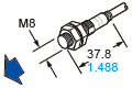
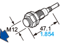
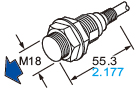
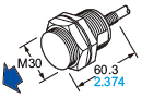
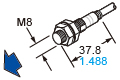
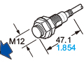
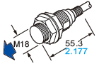
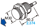
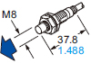
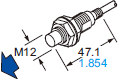
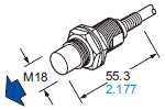
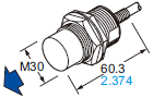
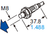
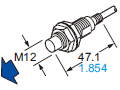
GX-308M(K)-□, GX-312M(K)-□, GX-318M(K)-□, GX-330M(K)-□
GX-308ML(K)-□, GX-312ML(K)-□, GX-318ML(K)-□, GX-330ML(K)-□
Sensor
Cable type / Pigtailed type

| Model No. | Shielded type | |||||||||
|---|---|---|---|---|---|---|---|---|---|---|
| A | B | C | D | E | F | G | H | I | J | |
| GX-308M(K) | M8 × 1 M8 × 0.039 | 37.8 1.488 | 4.4 0.173 | 26 1.024 | - | 10 0.394 | 4 0.157 | 3 0.118 | 15 0.591 | 13 0.512 |
| GX-312M(K) | M12 × 1 M12 × 0.039 | 47.1 1.854 | 3.7 0.146 | 33 1.299 | - | 12 0.472 | 4 0.157 | 4 0.157 | 21 0.827 | 17 0.669 |
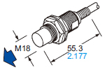
| GX-318M(K) | M18 × 1 M18 × 0.039 | 55.3 2.177 | 8.5 0.335 | 38 1.496 | - | 12 0.472 | 4 0.157 | 4 0.157 | 29 1.142 | 24 0.945 |
| GX-330M(K) | M30 × 1.5 M30 × 0.059 | 60.3 2.374 | 8.3 0.327 | 43 1.693 | - | 12 0.472 | 4 0.157 | 5 0.197 | 42 1.654 | 36 1.417 |
| Model No. | Non-shielded type | |||||||||
|---|---|---|---|---|---|---|---|---|---|---|
| A | B | C | D | E | F | G | H | I | J | |
| GX-308ML(K) | M8 × 1 M8 × 0.039 | 37.8 1.488 | 4.4 0.173 | 26 1.024 | 6 0.236 | 8 0.315 | - | 3 0.118 | 15 0.591 | 13 0.512 |
| GX-312ML(K) | M12 × 1 M12 × 0.039 | 47.1 1.854 | 3.7 0.146 | 33 1.299 | 7 0.276 | 10 0.394 | - | 4 0.157 | 21 0.827 | 17 0.669 |
| GX-318ML(K) | M18 × 1 M18 × 0.039 | 55.3 2.177 | 8.5 0.335 | 38 1.496 | 10 0.394 | 10 0.394 | - | 4 0.157 | 29 1.142 | 24 0.945 |
| GX-330ML | M30 × 1.5 M30 × 0.059 | 60.3 2.374 | 8.3 0.327 | 43 1.693 | 13 0.512 | 10 0.394 | - | 5 0.197 | 42 1.654 | 36 1.417 |
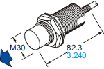
| GX-330MLK | M30 × 1.5 M30 × 0.059 | 82.3 3.240 | 8.3 0.327 | 65 2.559 | 15 0.591 | 10 0.394 | - | 5 0.197 | 42 1.654 | 36 1.417 |
Connector type

| Model No. | Shielded type | |||||||||
|---|---|---|---|---|---|---|---|---|---|---|
| A | B | C | D | E | F | G | H | I | J | |
| GX-312M(K) | M12 × 1 M12 × 0.039 | 48 1.890 | M12 × 1 M12 × 0.039 | 33 1.299 | - | 12 0.472 | 4 0.157 | 4 0.157 | 21 0.827 | 17 0.669 |
| GX-318M(K) | M18 × 1 M18 × 0.039 | 53 2.087 | M12 × 1 M12 × 0.039 | 38 1.496 | - | 12 0.472 | 4 0.157 | 4 0.157 | 29 1.142 | 24 0.945 |
| GX-330M(K) | M30 × 1.5 M30 × 0.059 | 58 2.283 | M12 × 1 M12 × 0.039 | 43 1.693 | - | 12 0.472 | 4 0.157 | 5 0.197 | 42 1.654 | 36 1.417 |
| Model No. | Non-shielded type | |||||||||
|---|---|---|---|---|---|---|---|---|---|---|
| A | B | C | D | E | F | G | H | I | J | |
| GX-312ML(K) | M12 × 1 M12 × 0.039 | 48 1.890 | M12 × 1 M12 × 0.039 | 33 1.299 | 7 0.276 | 10 0.394 | - | 4 0.157 | 21 0.827 | 17 0.669 |
| GX-318ML(K) | M18 × 1 M18 × 0.039 | 53 2.087 | M12 × 1 M12 × 0.039 | 38 1.496 | 10 0.394 | 10 0.394 | - | 4 0.157 | 29 1.142 | 24 0.945 |
| GX-330ML | M30 × 1.5 M30 × 0.059 | 58 2.283 | M12 × 1 M12 × 0.039 | 43 1.693 | 13 0.512 | 10 0.394 | - | 5 0.197 | 42 1.654 | 36 1.417 |
| GX-330MLK | M30 × 1.5 M30 × 0.059 | 80 3.150 | M12 × 1 M12 × 0.039 | 65 2.559 | 15 0.591 | 10 0.394 | - | 5 0.197 | 42 1.654 | 36 1.417 |
Note:M8 type models are not available in the connector type.
I/O Circuit and Wiring diagrams
- GX-3□S-□-N, GX-305M-□-N
- GX-3□S-□-P, GX-305M-□-P
- GX-3□M(K)-A-N, GX-3□ML(K)-A-N
- GX-3□M(K)-B-N, GX-3□ML(K)-B-N
- GX-3□M(K)-A-P, GX-3□ML(K)-A-P
- GX-3□M(K)-B-P, GX-3□ML(K)-B-P
GX-3□S-□-N
GX-305M-□-N
NPN output type
I/O circuit diagram

Note: Only GX-303S is 50 mA max.

Wiring diagram

GX-3□S-□-P
GX-305M-□-P
PNP output type
I/O circuit diagram

Note: Only GX-303S is 50 mA max.

Wiring diagram

GX-3□M(K)-A-N
GX-3□ML(K)-A-N
* Excluding M5 threaded type
NPN output, Normally open type
I/O circuit diagram

Note:In the case of the M8 threaded type:
200 mA max. (at -40 to +70 ℃ -40 to +158 ℉),
100 mA max. (at +70 to +85 ℃ +158 to +185 ℉)

Wiring diagram

Connector pin diagram
[Pigtailed type, Connector type]

GX-3□M(K)-B-N
GX-3□ML(K)-B-N
* Excluding M5 threaded type
NPN output, Normally closed type
I/O circuit diagram

Note:In the case of the M8 threaded type:
200 mA max. (at -40 to +70 ℃ -40 to +158 ℉),
100 mA max. (at +70 to +85 ℃ +158 to +185 ℉)

*1: Note that the lead color of the sensor and that of the matting cable are different.
Wiring diagram

*1: Note that the lead color of the sensor and that of the matting cable are different.
Connector pin diagram
[Pigtailed type, Connector type]

*1: Note that the lead color of the sensor and that of the matting cable are different.
GX-3□M(K)-A-P
GX-3□ML(K)-A-P
* Excluding M5 threaded type
PNP output, Normally open type
I/O circuit diagram
<When used as ordinary sensor>
[Standard I/O mode (SIO mode)]

Note:In the case of the M8 threaded type:
200 mA max. (at -40 to +70 ℃ -40 to +158 ℉),
100 mA max. (at +70 to +85 ℃ +158 to +185 ℉)

<When connected to IO-Link master>
[IO-Link communication mode (COM mode)]

Notes
1):In the case of the M8 threaded type:
200 mA max. (at -40 to +70 ℃ -40 to +158 ℉),
100 mA max. (at +70 to +85 ℃ +158 to +185 ℉)
2):In the IO-Link mode, the cable between the IO‑Link master and sensor must have a length of 20 m 65.617 ft or less.

Wiring diagram

Connector pin diagram
[Pigtailed type, Connector type]

GX-3□M(K)-B-P
GX-3□ML(K)-B-P
* Excluding M5 threaded type
PNP output, Normally closed type
I/O circuit diagram

Note:In the case of the M8 threaded type:
200 mA max. (at -40 to +70 ℃ -40 to +158 ℉),
100 mA max. (at +70 to +85 ℃ +158 to +185 ℉)

*1: Note that the lead color of the sensor and that of the matting cable are different.
Wiring diagram

*1: Note that the lead color of the sensor and that of the matting cable are different.
Connector pin diagram
[Pigtailed type, Connector type]

*1: Note that the lead color of the sensor and that of the matting cable are different.
Sensing characteristics
*TYPICAL
All models
Sensing field
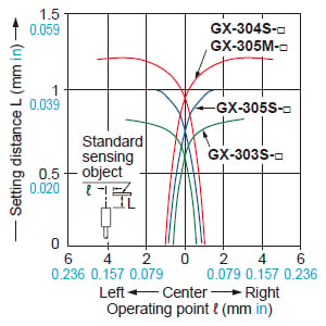
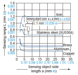
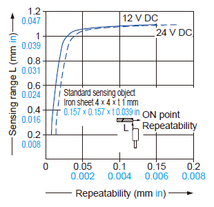
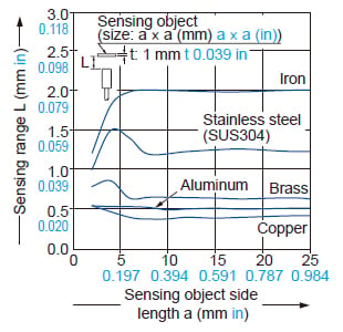
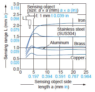
GX-303S-□
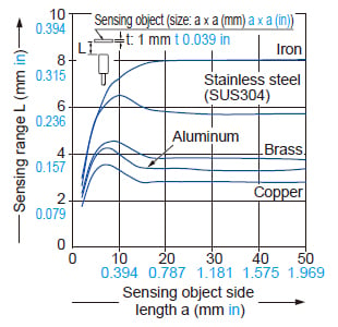
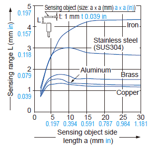
Correlation between sensing object size and sensing range
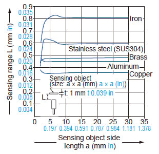
As the sensing object size becomes smaller than the standard size (iron sheet 3 × 3 × t 1 mm0.118 × 0.118 × t 0.039 in), the sensing range shortens as shown in the left figure.
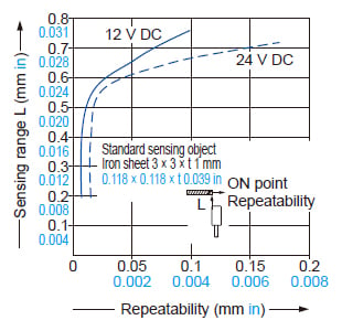
Correlation between sensing range and repeatability
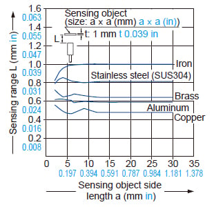
GX-304S-□
GX-305M-□
Correlation between sensing object size and sensing range
As the sensing object size becomes smaller than the standard size (iron sheet 4 × 4 × t 1 mm0.157 × 0.157 × t 0.039 in), the sensing range shortens as shown in the left figure.
Correlation between sensing range and repeatability
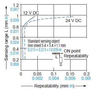
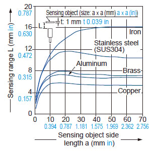
GX-305S-□
Correlation between sensing object size and sensing range
As the sensing object size becomes smaller than the standard size (iron sheet 5.4 × 5.4 × t 1 mm0.213 × 0.213 × t 0.039 in), the sensing range shortens as shown in the left figure.
Correlation between sensing range and repeatability
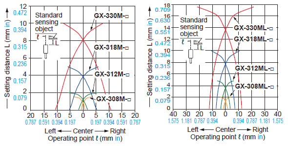
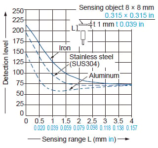
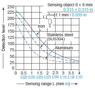
GX-308M-□
Correlation between sensing object size and sensing range
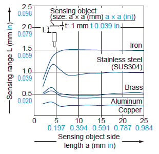
As the sensing object size becomes smaller than the standard size (iron sheet 8 × 8 × t 1 mm0.315 × 0.315 × t 0.039 in), the sensing range shortens as shown in the left figure.
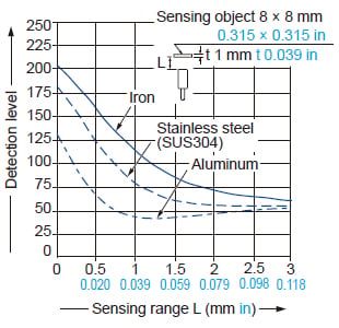
Correlation between monitor output and sensing range
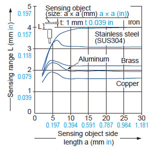
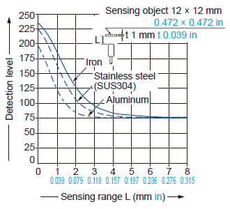
GX-312M-□
Correlation between sensing object size and sensing range
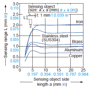
As the sensing object size becomes smaller than the standard size (iron sheet 12 × 12 × t 1 mm0.472 × 0.472 × t 0.039 in), the sensing range shortens as shown in the left figure.
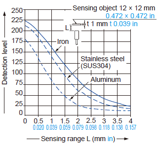
Correlation between monitor output and sensing range
GX-318M-□
Correlation between sensing object size and sensing range
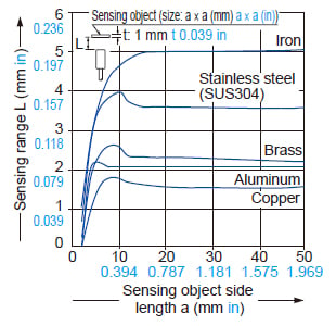
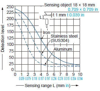
As the sensing object size becomes smaller than the standard size (iron sheet 18 × 18 × t 1 mm0.709 × 0.709 × t 0.039 in), the sensing range shortens as shown in the left figure.
Correlation between monitor output and sensing range
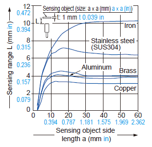
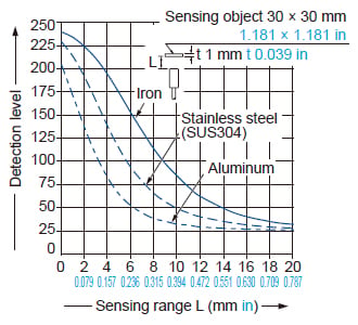
GX-330M-□
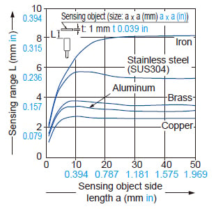
Correlation between sensing object size and sensing range
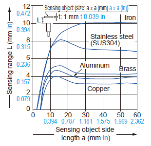
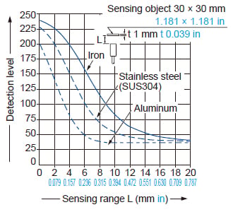
As the sensing object size becomes smaller than the standard size (iron sheet 30 × 30 × t 1 mm1.181 × 1.181 × t 0.039 in), the sensing range shortens as shown in the left figure.
Correlation between monitor output and sensing range
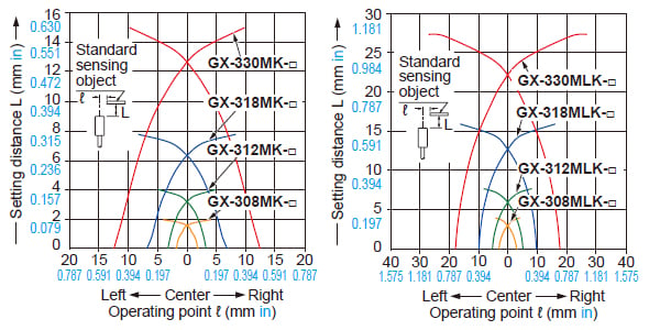
GX-308MK-□
Correlation between sensing object size and sensing range
As the sensing object size becomes smaller than the standard size (iron sheet 8 × 8 × t 1 mm0.315 × 0.315 × t 0.039 in), the sensing range shortens as shown in the left figure.
Correlation between monitor output and sensing range
GX-312MK-□
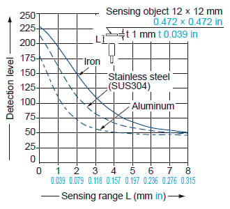
Correlation between sensing object size and sensing range
As the sensing object size becomes smaller than the standard size (iron sheet 12 × 12 × t 1 mm0.472 × 0.472 × t 0.039 in), the sensing range shortens as shown in the left figure.
Correlation between monitor output and sensing range
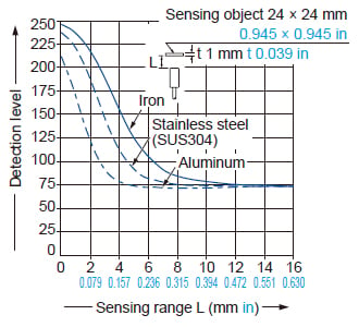
GX-318MK-□
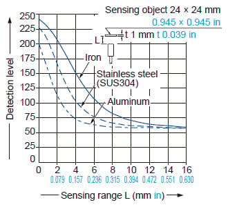
Correlation between sensing object size and sensing range
As the sensing object size becomes smaller than the standard size (iron sheet 24 × 24 × t 1 mm0.945 × 0.945 × t 0.039 in), the sensing range shortens as shown in the left figure.
Correlation between monitor output and sensing range
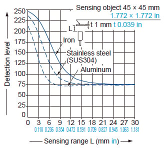
GX-330MK-□
Correlation between sensing object size and sensing range
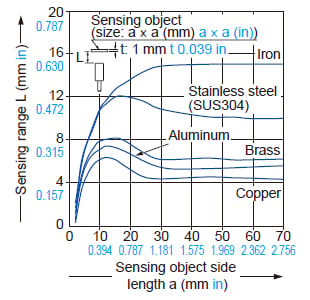
As the sensing object size becomes smaller than the standard size (iron sheet 45 × 45 × t 1 mm1.772 × 1.772 × t 0.039 in), the sensing range shortens as shown in the left figure.
Correlation between monitor output and sensing range
GX-308ML-□
Correlation between sensing object size and sensing range
As the sensing object size becomes smaller than the standard size (iron sheet 8 × 8 × t 1 mm0.315 × 0.315 × t 0.039 in), the sensing range shortens as shown in the left figure.
Correlation between monitor output and sensing range
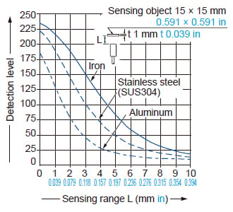
GX-312ML-□
Correlation between sensing object size and sensing range
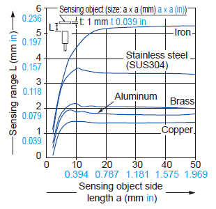
As the sensing object size becomes smaller than the standard size (iron sheet 15 × 15 × t 1 mm0.591 × 0.591 × t 0.039 in), the sensing range shortens as shown in the left figure.
Correlation between monitor output and sensing range
GX-318ML-□
Correlation between sensing object size and sensing range
As the sensing object size becomes smaller than the standard size (iron sheet 30 × 30 × t 1 mm1.181 × 1.181 × t 0.039 in), the sensing range shortens as shown in the left figure.
Correlation between monitor output and sensing range
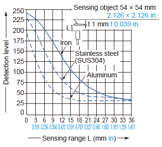
GX-330ML-□
Correlation between sensing object size and sensing range
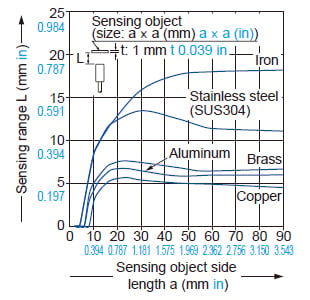
As the sensing object size becomes smaller than the standard size (iron sheet 54 × 54 × t 1 mm2.126 × 2.126 × t 0.039 in), the sensing range shortens as shown in the left figure.
Correlation between monitor output and sensing range
GX-308MLK-□
Correlation between sensing object size and sensing range
As the sensing object size becomes smaller than the standard size (iron sheet 12 × 12 × t 1 mm0.472 × 0.472 × t 0.039 in), the sensing range shortens as shown in the left figure.
Correlation between monitor output and sensing range
GX-312MLK-□
Correlation between sensing object size and sensing range
As the sensing object size becomes smaller than the standard size (iron sheet 24 × 24 × t 1 mm0.945 × 0.945 × t 0.039 in), the sensing range shortens as shown in the left figure.
Correlation between monitor output and sensing range
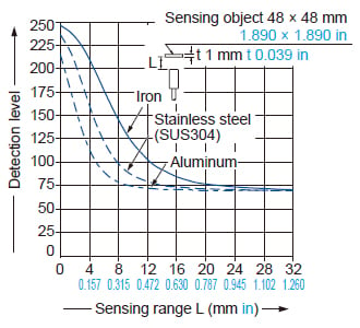
GX-318MLK-□
Correlation between sensing object size and sensing range
As the sensing object size becomes smaller than the standard size (iron sheet 48 × 48 × t 1 mm1.890 × 1.890 × t 0.039 in), the sensing range shortens as shown in the left figure.
Correlation between monitor output and sensing range
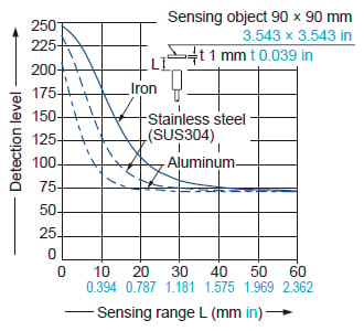
GX-330MLK-□
Correlation between sensing object size and sensing range
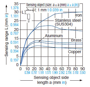
As the sensing object size becomes smaller than the standard size (iron sheet 90 × 90 × t 1 mm3.543 × 3.543 × t 0.039 in), the sensing range shortens as shown in the left figure.
Correlation between monitor output and sensing range
Mounting
- The tightening torque should be under the value given below.
Installation using set screw
- Do not tighten the product mounting nuts with excessive force.
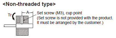
| Model No. | Tightening torque | Set screw location A (mm in) |
|---|---|---|
| GX-303S | 0.2N・m | 13 to 21 0.512 to 0.827 |
| GX-304S | 8 to 21 0.315 to 0.827 | |
| GX-305S | 0.4N・m |
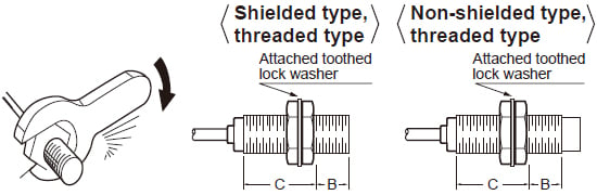
Installation using nut
- Do not tighten the nut with excessive force. Be sure to install the toothed locked washer.
- In the case of the M8 threaded type, the allowable strength differs depending on the distance from the tip of the head. The following table shows the allowable tightening strengths for section B and section C shown in the diagram. (Section B starts from the tip of the head and its dimension is indicated in the table. Section C includes the nut on the head side. Therefore, if the nut extends into section B even slightly, the strength of section B is applicable.)
- The following allowable tightening strengths are applicable when the washer is installed.
| Model No. (Shielded type) | B | C | |
|---|---|---|---|
| Dimension (mm in) | Tightening torque | Tightening torque | |
| GX-305M | - | 1N・m | |
| GX-308M(K) | 9 0.354 | 9N・m | 12N・m |
| GX-312M(K) | - | 30N・m | |
| GX-318M(K) | - | 70N・m | |
| GX-330M(K) | - | 180N・m | |
| Model No. (Non-shielded type) | B | C | |
|---|---|---|---|
| Dimension (mm in) | Tightening torque | Tightening torque | |
| GX-308ML(K) | 3 0.118 | 9N・m | 12N・m |
| GX-312ML(K) | - | 30N・m | |
| GX-318ML(K) | - | 70N・m | |
| GX-330ML(K) | - | 180N・m | |
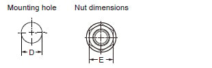
| 型式名 | D(mm in) | E(mm in) |
|---|---|---|
| GX-303S | ø3.3+0.50 ø0.130+0.01970 | - |
| GX-304S | ø4.2+0.50 ø0.165+0.01970 | - |
| GX-305S | ø5.7+0.50 ø0.224+0.01970 | - |
| GX-305M | ø5.5+0.50 ø0.217+0.01970 | - |
| GX-308M(K) GX-308ML(K) | ø8.5+0.50 ø0.335+0.01970 | 13 0.512 |
| GX-312M(K) GX-312ML(K) | ø12.5+0.50 ø0.492+0.01970 | 17 0.669 |
| GX-318M(K) GX-318ML(K) | ø18.5+0.50 ø0.728+0.01970 | 24 0.945 |
| GX-330M(K) GX-330ML(K) | ø30.5+0.50 ø1.201+0.01970 | 36 1.417 |
Bending radius of lead-out cable section
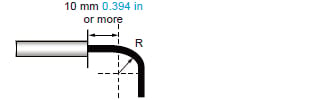
| Model No. | Bending radius R |
|---|---|
| GX-303S | 7 mm 0.276 in or more |
| GX-304S | 9 mm 0.354 in or more |
| GX-305S | |
| GX-305M |
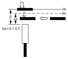
Installing small-diameter sensor
- Please use the sensor after confirming the installation distance by following (a) and (b) with an actual detection object when you install.
(a) The detection distance receives the influence by the material of the detection object, thickness, shape, and the size. So, the detection object is brought close to the front side of the sensor and detection distance (S) is measured. For the effect of the material, see the graph, "Correlation between sensing object size and sensing range".
(b) Please decide installation distance (Sa) with S × 70% or less after measuring sensing distance(S).
- Please use the sensor after confirming the installation distance by following (a) and (b) with an actual detection object when you install.
- Please install the sensor to come within the range of (Sa) when the detection object moves from vertical direction.
- Please install the sensor to pass within the range of (Sa) when the detection object moves from horizontal direction.
- When using the sensor, refer to the "Standard sensing object" specified in the specifications and the graph, "Correlation between sensing object size and sensing range".
Distance from surrounding metal
- As metal around the sensor may affect the sensing performance, pay attention to the following points.
Influence of surrounding metal
- The surrounding metal will affect the sensing performance. Keep the minimum distance specified in the table below.
- When mounting the sensor using a nut, use the nut and washer provided with the product.
- The type of the provided nut varies in different models. See the external dimensions diagrams for the detail of the shape.
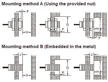
(Unit:mm in)
| Model No. (Shielded type) | Mounting method A | Mounting method B | |||||||
|---|---|---|---|---|---|---|---|---|---|
| F | G | H | I | J | G | K | H | I | |
| GX-303S | - | - | - | - | 0 | ø3 ø0.118 | 0 | 3 0.118 | 8 0.315 |
| GX-304S | - | - | - | - | 0 | ø4 ø0.157 | 0 | 5 0.197 | 10 0.394 |
| GX-305S | - | - | - | - | 0 | ø5.4 ø0.213 | 0 | 3 0.118 | 8 0.315 |
| GX-305M | 0 | ø5 ø0.197 | 5 0.197 | 10 0.394 | 0 | ø5 ø0.197 | 0 | 5 0.197 | 10 0.394 |
| GX-308M | 0 | ø8 ø0.315 | 4.5 0.177 | 12 0.472 | 0 | ø8 ø0.315 | 0 | 4.5 0.177 | 12 0.472 |
| GX-312M | 0 | ø12 ø0.472 | 8 0.315 | 18 0.709 | 0 | ø12 ø0.472 | 0 | 8 0.315 | 18 0.709 |
| GX-318M | 0 | ø18 ø0.709 | 20 0.787 | 27 1.063 | 0 | ø18 ø0.709 | 0 | 20 0.787 | 27 1.063 |
| GX-330M | 0 | ø30 ø1.181 | 40 1.575 | 45 1.772 | 0 | ø30 ø1.181 | 0 | 40 1.575 | 45 1.772 |
| GX-308MK | 0 | ø8 ø0.315 | 4.5 0.177 | 12 0.472 | 0 | ø8 ø0.315 | 0 | 4.5 0.177 | 12 0.472 |
| GX-312MK | 0 | ø18 ø0.709 | 12 0.472 | 18 0.709 | 2.4 0.094 | ø18 ø0.709 | 2.4 0.094 | 12 0.472 | 18 0.709 |
| GX-318MK | 0 | ø27 ø1.063 | 24 0.945 | 27 1.063 | 3.6 0.142 | ø27 ø1.063 | 3.6 0.142 | 24 0.945 | 27 1.063 |
| GX-330MK | 0 | ø45 ø1.772 | 45 1.772 | 45 1.772 | 6 0.236 | ø45 ø1.772 | 6 0.236 | 45 1.772 | 45 1.772 |
| Model No. (Non-shielded type) | Mounting method A | Mounting method B | |||||||
|---|---|---|---|---|---|---|---|---|---|
| F | G | H | I | J | G | K | H | I | |
| GX-308ML | 6 0.236 | ø24 ø0.945 | 8 0.315 | 24 0.945 | 6 0.236 | ø24 ø0.945 | 6 0.236 | 8 0.315 | 24 0.945 |
| GX-312ML | 11 0.433 | ø40 ø1.575 | 20 0.787 | 36 1.417 | 15 0.591 | ø40 ø1.575 | 15 0.591 | 20 0.787 | 36 1.417 |
| GX-318ML | 18 0.709 | ø55 ø2.165 | 40 1.575 | 54 2.126 | 22 0.866 | ø55 ø2.165 | 22 0.866 | 40 1.575 | 54 2.126 |
| GX-330ML | 25 0.984 | ø90 ø3.543 | 70 2.756 | 90 3.543 | 30 1.181 | ø90 ø3.543 | 30 1.181 | 70 2.756 | 90 3.543 |
| GX-308MLK | 9 0.354 | ø24 ø0.945 | 8 0.315 | 24 0.945 | 12 0.472 | ø24 ø0.945 | 12 0.472 | 8 0.315 | 24 0.945 |
| GX-312MLK | 11 0.433 | ø40 ø1.575 | 20 0.787 | 40 1.575 | 15 0.591 | ø40 ø1.575 | 15 0.591 | 20 0.787 | 40 1.575 |
| GX-318MLK | 21 0.827 | ø70 ø2.756 | 48 1.890 | 70 2.756 | 25 0.984 | ø70 ø2.756 | 25 0.984 | 48 1.890 | 70 2.756 |
| GX-330MLK | 40 1.575 | ø120 ø4.724 | 90 3.543 | 120 4.724 | 45 1.772 | ø120 ø4.724 | 45 1.772 | 90 3.543 | 120 4.724 |
Mutual interference
- When two or more sensors are installed in parallel or face to face, keep the minimum separation distance specified below to avoid mutual interference.
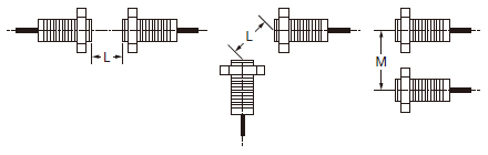
| Model No. (Shielded type) | L (mm in) | M (mm in) |
|---|---|---|
| GX-303S | 20 0.787 | 15 0.591 |
| GX-304S | 20 0.787 | 15 0.591 |
| GX-305S | 20 0.787 | 15 0.591 |
| GX-305M | 20 0.787 | 15 0.591 |
| GX-308M(K) | 20 0.787 | 15 0.591 |
| GX-312M(K) | 30 1.181 | 20 0.787 |
| GX-318M | 50 1.969 | 35 1.378 |
| GX-318MK | 60 2.362 | 35 1.378 |
| GX-330M | 100 3.937 | 70 2.756 |
| GX-330MK | 110 4.331 | 90 3.543 |
| Model No. (Non-shielded type) | L (mm in) | M (mm in) |
|---|---|---|
| GX-308ML(K) | 80 3.150 | 60 2.362 |
| GX-312ML(K) | 120 4.724 | 100 3.937 |
| GX-318ML | 200 7.874 | 110 4.331 |
| GX-318MLK | 200 7.874 | 120 4.724 |
| GX-330ML | 300 11.811 | 200 7.874 |
| GX-330MLK | 350 13.780 | 300 11.811 |
Timing chart
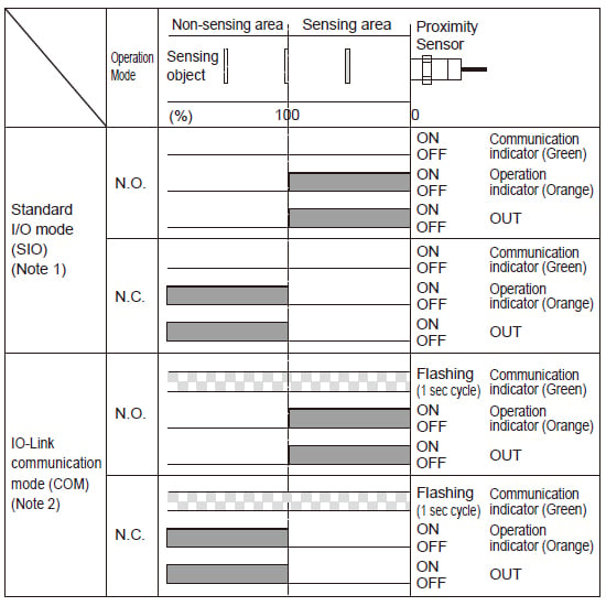
Notes:
1)When sensors that are not compatible with IO-Link are used or when IO-Link compatible models are used as ordinary sensors, they operate in the standard I/O mode (SIO mode).
2)The operation mode can be changed by the IO-Link communications. The timer function of the output can be set up by the IO-Link communications.
Others
- This product has been developed / produced for industrial use only.
- Do not install the product in the following locations. Doing so may result in product failure or malfunction.
∙ Outdoor locations directly subject to sunlight, rain, snow, water droplets, or oil.
∙ Locations subject to atmospheres with chemical vapors, in particular solvents and acids.
∙ Locations subject to corrosive gases. - The product may malfunction if used near ultrasonic cleaning equipment, high-frequency equipment, transceivers, cellular phones, inverters, or other devices that generate a high-frequency electric field.
- Laying the product wiring in the same conduit or duct as high-voltage wires or power lines may result in incorrect operation and damage due to induction. Wire the product using a separate conduit or independent conduit.
- The following conditions shall be observed if you use the product under an environment using cutting oil that may affect product’s life and/or performance.
∙ Usage in oil or water is prohibited. - Impact on the product life may differ depending on the oil you use. Before using the cutting oil, make sure that it should not cause deterioration or degradation of sealing components.
- Never use thinner or other solvents. Otherwise, the product surface may be dissolved.
- When turning ON the power by influence of temperature environment, an output mis-pulse sometimes occurs.
After the product has passed for 300 ms after turning ON, please use in the stable state. If the sensing object is located near the sensor’s sensing surface, an output mis-pulse may be generated for 300 ms or longer at the time of power-on.
Be sure to check the product for proper operation under actual operating condition before using. - The product is adjusted with a high degree of accuracy, so do not use in the environment with sudden temperature change.
- Do not attempt to disassemble, repair, or modify the product.
- Do not use a voltage that exceeds the rated operating voltage range. Applying a voltage that is higher than the operating voltage range may result in damage or burnout.
- Be sure that the power supply polarity and other wiring is correct. Incorrect wiring may cause explosion or burnout.
- If the power supply is connected directly without a load, the internal elements may explode or burn. Be sure to insert a load when connecting the power supply.
- Please use gloves to protect yourself from injury caused by screw.
- For the connector type and pigtailed type, check the specifications of the connector cable to be used. Please do not use it under conditions that exceed the range of its specifications of both the product and the connector cable.
- Please make sure there is no foreign matter in connector part before connecting the connector cable to the connector type and pigtailed type.
- In the IO-Link mode, the cable between the IO-Link master and sensor must have a length of 20 m 65.617 ft or less.