IO-Link Master Unit
Download
-
Basic Information
-
Order guide
-
Option
-
Specifications
-
Dimensions
-
Cautions For Use
Basic Information

Receive sensor information on a gigabit network!
Contact Us
Features

Smart collection of on-site sensor information
Collecting on-site sensor-level information is essential to making the manufacturing floor “visible” and IoT enabled.
Panasonic Industry provides an information collection solution that is easy, low-cost, and maintains information quality.
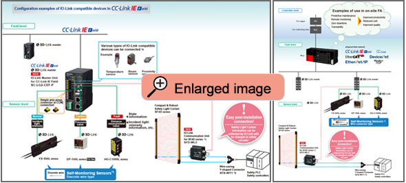
Using Panasonic Industry's self-monitoring sensors and IO-Link master, incident light intensity, pressure values, and distance measurement values can be sent as digital data with certitude to a host controller.
The sensors diagnose their own state and inform you of the result, making it easy to identify the cause of problems.
By reducing the amount of data collected, you can alleviate the labor spent organizing and analyzing data.

IO-Link Master Unit [SC-LG2-CEF-P]

CC-Link IE Field compatible
Can be used as an intelligent device station.
Up to 8 IO-Link compatible devices and IO-Link non-compatible devices (PNP output) can be connected
As an IO-Link master, the unit supports up to 8 connection channels.
Simple wire-press connector (e-CON) enables easy connection
Available as an option (sold separately).

IO-Link device settings can be set at once from the host tool
Settings can be configured at once from the host tool (SC-LG-CEF Configuration Tool) via a Mitsubishi Electric Corporation PLC.

Device monitor screen
Equipped with a device monitor screen for convenient confirmation and a language selection function
SC-LG-CEF Configuration Tool is a software application program for Windows® that can acquire measurement data from the IO-Link Master Unit for CC-Link IE Field SC-LG2-CEF-P and devices connected to it, as well as set and read various parameters.
* Windows is a registered trademark or trademark of Microsoft Corporation in the U.S. and/or other countries.
Note: 1) When using SC-LG-CEF Configuration Tool, use the following models.
・MELSEC-Q Series QJ71GF11-T2
・MELSEC-L Series LJ71GF11-T2
・MELSEC iQ-R Series RJ71EN71
・MELSEC iQ-R Series RJ71GF11-T2
The SC-LG-CEF Configuration Tool cannot be used with models other than those listed above.
SC-LG-CEF Configuration Tool
"SC-LG-CEF Configuration Tool"is available for download.
* To download, you need to enter your customer information.
>>Go to Data download.
Order guide
IO-link master unit
Simple wire-press connector (e-CON) is not included with the IO-Link master unit. Please purchase separately.
| Type | Model No. | Description |
|---|---|---|
| IO-Link master unit for CC-Link IE Field
| SC-LG2-CEF-P | By connecting this to an IO-Link compatible device, you can acquire measurement data and set and acquire parameters from CC-Link IE Field communication. You can also connect this to an IO-Link non-compatible device (PNP output) that has digital input / output functions (ON/OFF signal). You can acquire the input state of the ON/OFF signal of the IO-Link non-compatible device from CC-Link IE Field communication, and output the ON/OFF signal to the IO-Link non-compatible device. |
IO-Link compatible devices
For details on each sensor, refer to our website.
- Digital Fiber Sensor FX-550L (Discrete wire type)
- Dual Display Digital Pressure Sensor [For Gas] DP-100L (Discrete wire type)
- CMOS Type Micro Laser Distance Sensor HG-C1000L (Discrete wire type)
- Cylindrical Inductive Proximity Sensor [Amplifier Built-in / DC 3-wire Type] GX-300 (M8/M12/M18/M30 Threaded, Normally open type)
Option
| Type | Appearance | Model No. | Description |
|---|---|---|---|
| Simple wire-press connector (e-CON) |
| CN-EP2 | • Applicable wire: 0.1 to 0.5 mm2 (AWG27 to 20) • Wire diameter without jacket: ø1.0 to ø1.15 mm ø0.039 to ø0.045 in • Plug housing color: Yellow [5 pcs. per set] |
| CN-EP3 | • Applicable wire: 0.1 to 0.5 mm2 (AWG27 to 20) • Wire diameter without jacket: ø0.6 to ø0.9 mm ø0.024 to ø0.035 in • Plug housing color: Orange [5 pcs. per set] |
IO-Link communication unit for SF4D series
SFD-WL3
For details, refer to "Compact & Robust Safety Light Curtain [Type 4 PLe SIL3] SF4D" page.

Recommended simple wirepress connector (e-CON)
TE Connectivity Japan G.K.
Model: 1473562-4
Note: Contact the manufacturer for details of the recommended products.
Recommended power connector
PHOENIX CONTACT
Product code: Equivalent to MC1.5/5-ST-3.5AU
Note: Contact the manufacturer for details of the recommended products.
Specifications
| Model No. | SC-LG2-CEF-P | |||
|---|---|---|---|---|
| Applicable regulations | CE Marking (EMC Regulations, RoHS Regulations), UKCA Marking (EMC Regulations, RoHS Regulations) | |||
| Supply voltage | 24 V DC+10-15 %, Ripple P-P 10 % or less | |||
| CC-Link IE Field specifications | Current consumption | 200 mA or less | ||
| Communication method | CC-Link IE Field | |||
| Remote station type | Intelligent device station | |||
| Network number setting | 1 to 239 (decimal) [1 to EF (hex)] (0 and 240 or more: Error) | |||
| Cyclic transmission[Maximum number of link points per station] | RX/RY: Maximum 112 points (112 bits) / Maximum 112 points (112 bits) RWr/RWw: Maximum 132 points (132 words) / Maximum 132 points (132 words) | |||
| Transient transmission | For server function only, message size: 2 kbytes (maximum) | |||
| Number of ports | 1000BASE-T Ethernet port (RJ45) × 2 | |||
| Station number setting | 1 to 120 (decimal)(0 and 121 or more: Error) | |||
| Communication speed | 1 Gbps | |||
| Communication cable | Category 5e or higher Ethernet cables that satisfy the 1000BASE-T standard (Double shielded twisted pair cable or straight cable)(Note 1) | |||
| Transmission line type | Line type, star type (line/star mixed type also possible), ring type | |||
| Maximum distance between stations | 100 m 328.084 ft | |||
| Maximum number of stations that can be connected | 121 (1 master station, 120 slave stations) | |||
| Maximum number of stages of cascade connection | 20 | |||
| IO-Link specifications | Current consumption | 150 mA or less (excluding the current consumption of connected IO-Link devices) | ||
| Allowable passing current | 3 A or less (Note 2) | |||
| Communication method | IO-Link V1.0 / V1.1 | |||
| Number of ports | e-CON compliant connector port for IO-Link × 8 | |||
| Communication speed | COM1 (4.8 kbps), COM2 (38.4 kbps), COM3 (230.4 kbps) Automatically set by IO-Link device | |||
| Current supplied to device (L+, L-) | Maximum 200 mA per port (Note 2) | |||
| Digital I/O (C/Q) (Note 2)(Note 3) | IO-Link mode | Compliance with the IO-Link standard | ||
| SIO mode | During input setting | PNP input (Sink current: Max. 15 mA) | ||
| During output setting | Push-pull output (Drive capacity: Max.100 mA) | |||
| Digital input (DI) (Note 2)(Note 3) | PNP input (Sink current: Max. 15 mA) | |||
| Communication cable | Unshielded | |||
| Maximum cable length | 20 m 65.617 ft | |||
| IO-Link connector | e-CON compliant connector (4-pin type)(Note 4) | |||
| Environmental resistance | Ambient temperature | -10 to +55 ℃ +14 to +131 ℉ (No dew condensation or icing allowed), Storage: -20 to +70 ℃ -4 to +158 ℉ | ||
| Ambient humidity | 35 to 85 % RH, Storage: 35 to 85 % RH | |||
| Voltage withstandability | 1,000 V AC for one min. between all supply terminals connected together and enclosure | |||
| Insulation resistance | 20 MΩ or more with 250 V DC megger between all supply terminals connected together and enclosure | |||
| Vibration resistance | 10 to 150 Hz frequency, 0.75 mm 0.03 in double amplitude (10 to 58 Hz), maximum acceleration 49 m/s2, (58 to 150 Hz) in X, Y, and Z directions for two hours each | |||
| Shock resistance | 98 m/s2 (10 G approx.) in X, Y, and Z directions three times each | |||
| Grounding method | Power supply connector is equipped with a frame ground (F.G.) RJ45 connector shield: Directly connected to ground terminal Internal circuit: C coupling, Casing: Floating type | |||
| Limit to the number of flash memory save operations | 100,000 (Note 5) | |||
| Material | Case: Polycarbonate | |||
| Weight | Net weight: 210 g approx., Gross weight: 270 g approx. | |||
| Accessory | Power supply connector: 1 pc. | |||
Notes:
1) Use a cable recommended by CC-Link Partner Association.
2) Take care that the total consumption current of connected devices and the unit on the IO-Link side does not exceed the allowable passing current.
Power to devices (L+, L-), digital I/O (C/Q), and digital input (DI) are supplied from IO-Link (+V, -V) on the power supply connector.
3) Operation settings for digital I/O (C/Q) and digital input (DI) must be configured with CC-Link IE Field.
If operation settings are not configured, they will not operate.
4) For the connectors for connecting devices to this product, purchase simple wire-press connector (e-CON) CN-EP2 (5 pcs. set) or CN-EP3 (5 pcs. set) or the recommended product.
5) This product saves settings in internal flash memory.
Dimensions
Unit: mm inSC-LG2-CEF-P
IO-Link master unit for CC-Link IE Field

Cautions For Use
- Never use this product as a sensing device for personnel protection.
- In case of using sensing devices for personnel protection, use products which meet laws and standards, such as OSHA, ANSI or IEC etc., for personnel protection applicable in each region or country.
User’s Manuals
"SC-LG2-CEF-P User's Manual" and "SC-LG-CEF Configuration Tool User's Manual" are available. These can be downloaded from our website.
* "SC-LG-CEF Configuration Tool User’s Manual" is included with "SC-LG-CEF Configuration Tool".


