------------------------------ Tab1 showing ------------------------------
Basic Information
The Industry’s Highest-Class*
Measurement Accuracy Is Now Yours.
* Among thru-beam type digital sensors, as of September 2023 in-company survey


-
November 2020
New functions will be added to thru-beam type digital displacement sensor HG-T series- Invalidates sudden changes in measurements (Tab cancel function)
- User-specified edge detection mode
- Hold state output (external output)
- Measured value reversal function
-
Communication Unit for Digital Displacement sensor SC-HG1
 Please check "Communication Unit for Digital Displacement sensor SC-HG1" which can connect digital displacement sensor controller as well.
Features
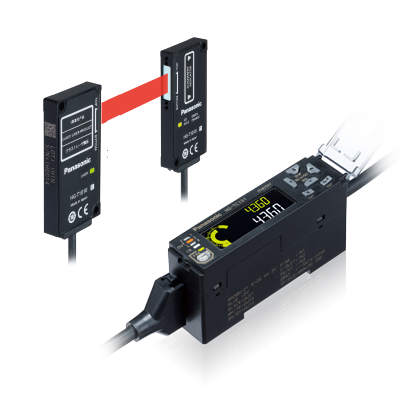
Sensor that diagnoses its own state. Featuring a self-monitoring function! 
Self-monitoring function released by using the digital displacement sensor communication unit SC-HG1 in combination with digital displacement sensor HG-S series and HG-T series.
>>HG-S / HG-T self-monitoring function
>>Communication Unit for Digital Displacement Sensors SC-HG1

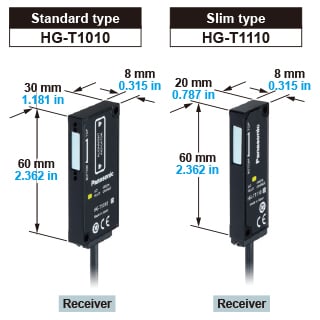
Ultra-slim
The ultra-slim unit with a thickness of 8 mm 0.315 in allows easy installation in a limited space such as the inside of equipment.

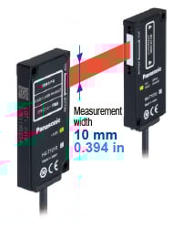
Wide-angle measurement
The belt-shaped laser beam with a measurement width of 10 mm 0.394 in is used for measurement of dimensions and positions.
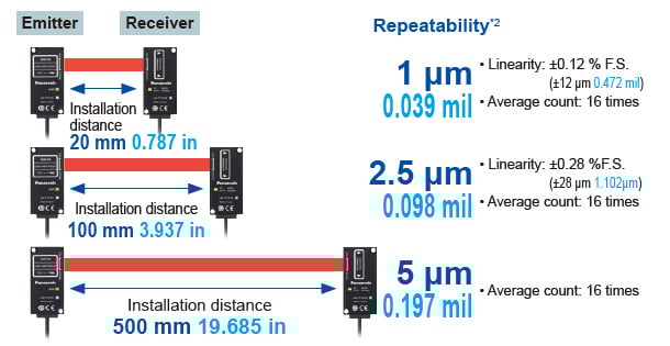
Industry’s highest*1 measurement accuracy
The HG-T series boasts repeatability*2 of 1 μm 0.039 mil and offers the highest*1 measurement accuracy in the industry.
●Sampling cycle setting can be selected from two options.
Standard: 1 ms, High speed: 0.5 ms.
●Average count setting can be selected from 11 options.
1 time, 2 times, 4 times, 8 times, 16 times, 32 times, 64 times, 128 times, 256 times, 512 times, 1,024 times
*1 As of September 2023, in-company survey
*2 This is the P-P value of digital measurement value with half shading at the middle position of the installation distance.
Two types of sensor heads are available.
Two types of sensor heads, one with a standard type receiver and the other with a slim type receiver, are available.
Side view attachment is available (optional). [HG-T1010]
Side view attachment (optional) is available for the standard type sensor head HG-T1010. This attachment can bend the laser beam at a right angle to allow flexible installation of the sensor head.
![Side view attachment is available (optional). [HG-T1010]](https://tp.industry.panasonic.com/hubfs/pid-corp/products/fasys/measurement/measurement/hg-t/images/pic06.jpg)
*Two side view attachment units are required when using the attachment on both emitter and receiver.
*The slim type sensor head HG-T1110 cannot be mounted with the side view attachment.
*Be sure to confirm proper detection using actual equipment in advance when using the attachment.
Lithium-ion battery winding section
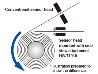
Use of the side view attachment enables the installation of the sensor head closer to the winding section than when a conventional sensor head is used, thus contributing to the improvement of winding accuracy.
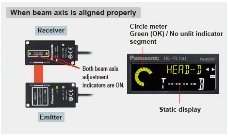
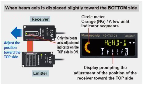
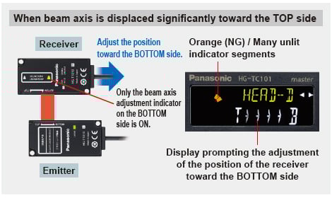
Beam axis adjustment assist function
The standard type sensor head HG-T1010 indicates the direction of receiver displacement relative to the emitter on the controller's display screen and with the beam axis adjustment indicators on the receiver in an easy-to-understand fashion.
* The slim type sensor head HG-T1110 displays the displacement information only on the
controller's display section.
Automatic emitter / receiver cable recognition
The HG-T series automatically recognizes the positional relationship of the emitter and receiver connected to the sensor head connection cable at the time the controller is turned ON. This function eliminates the need for identifying the correct cables to connect to the emitter and receiver. Wiring can be completed by simply attaching the connectors to the emitter and receiver.
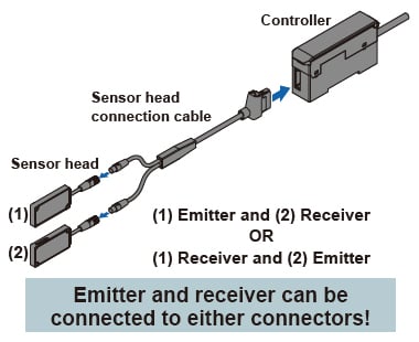
* The sensor head connection cable is branched into two cables on the sensor head connecting side, but the two cables can be connected interchangeably to the emitter and receiver.
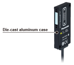
Die-cast aluminum case
The sensor head case is made of light and strong die-cast aluminum. It minimizes measurement fluctuations due to temperature effects. The die-cast aluminum case does not easily become distorted in shape by tightening of mounting screws as compared to a resin case. It is highly resistant to deterioration due to ageing. This robust case helps prevent deviations of beam axis alignment.
IP67 protection
The HG-T series features a protection structure of IP67(IEC) so it can be used in a place where the product may be exposed to water or large amounts of dust.
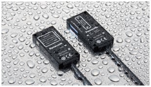
*Note that if the beam emitting / receiving surfaces of the sensor head are adhered with water or dust, correct measurements become inaccurate.*The sensor head is watertight, but the connectors are not structurally resistant to dust, water or corrosion. Therefore, the HG-T series cannot be submerged in water or placed under falling water for measurement operation. Be sure to use the product in an appropriate environment.

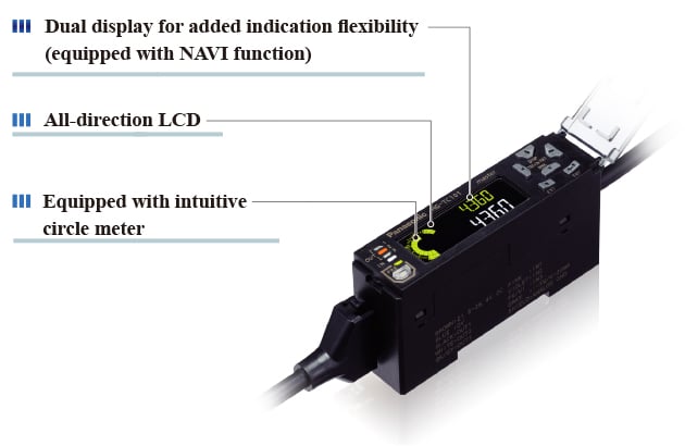
Dual display for added indication flexibility (equipped with NAVI function)
The 2-line digital display simultaneously shows head measurement (measured value) and judgment value (calculated value).
All-direction LCD
The high-contrast LCD provides sharp and clear indications and wide viewing angle.
Equipped with intuitive circle meter
Values between allowable maximum and minimum values are indicated in green. Values outside of the allowable range are indicated in orange. This provides at-a-glance understanding of the margin to the tolerance limits.

Six types of detection modes
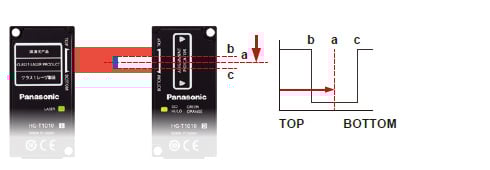
User-specified edge detection mode
Two points can be arbitrarily specified from multiple edges of the measurement object to be used for measurement, and the distance between the two points is measured.
* This change will be applied from production in November 2020.
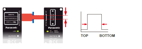
Industry's First!*
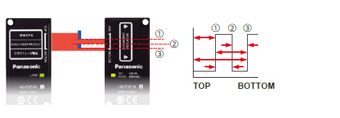
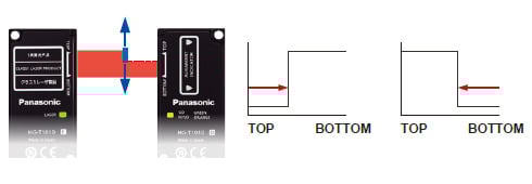
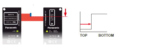
Auto edge detection mode
Edge detection can be started from either the TOP or BOTTOM without registering the detection direction. This eliminates the need for checking the detection direction.
* As of January 2019, according to in-company survey
Edge detection mode
External form / width detection mode
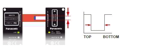
Inside diameter / gap detection mode
Central position detection mode
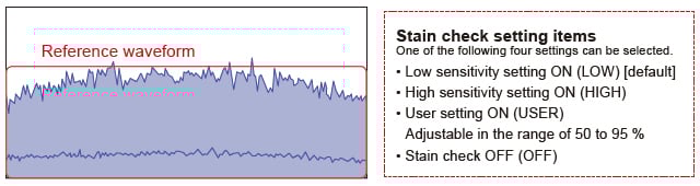
Monitoring of effects caused by stains
Notifies when the detection performance decreases due to accumulated stains.
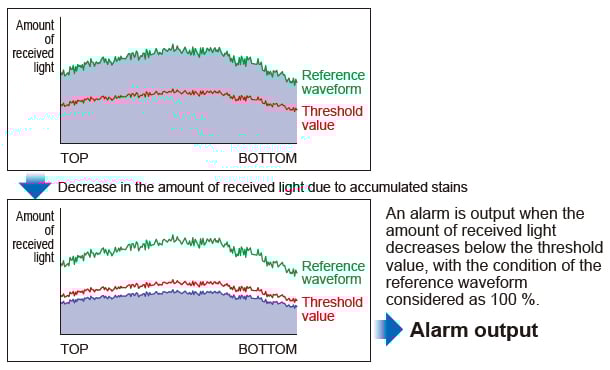
Checks the degree of contamination based on the amount of light of the reference waveform (considered as 100 %).
*The reference waveform can be confirmed by using a combination of the “HG-T Configuration Tool” USB-based PC setting software and USB communication unit SC-HG1-USB or RS-485 communication unit SC-HG1-485. For details, refer to "Software">>Go to "Software" page
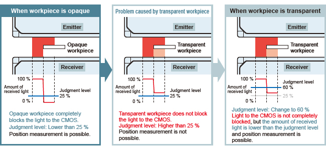
Stable measurement of even transparent workpieces
The judgment level can be adjusted according to the degree of transparency.
Elimination of effects caused by fine foreign matters
The judgment filter value can be adjusted for the prevention of erroneous detections due to fine foreign matters.
The judgment filter value can be set to a desired value between 3 and 50.
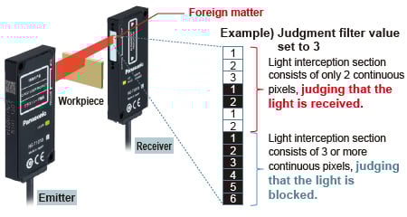
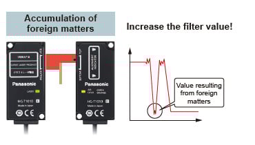
Increasing the filter value ignores values resulting from foreign matters.
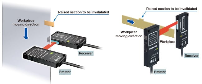
Invalidates sudden changes in measurements
If there is a sudden change in the edge position of the work piece, the change is invalidated and the judgement value is stabilized.
* This change will be applied from production in November 2020.

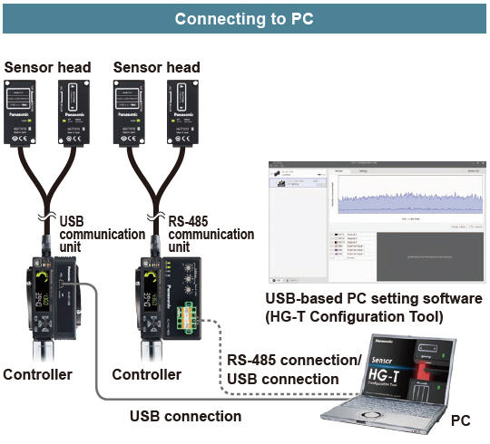
The USB communication unit provides convenient functions that facilitate the setting of the HG-T series while observing the waveform of received light by operating the dedicated USB-based PC setting software. The USB-based PC setting software can be downloaded free from our website.

*1 When connected to the communication unit for digital displacement sensor, up to 14 slave units can be connected per master unit.
*2 Dependent on PC environment.
USB-based PC setting software
HG-T Configuration Tool
For details, refer to "Software" page.
>>Go to Software
------------------------------ Tab2 showing ------------------------------


Shaft diameter measurement


------------------------------ Tab3 showing ------------------------------

Receiver: 8 × 30 × 60 mm 0.315 × 1.181 × 2.362 in

Receiver: 8 × 20 × 60 mm (0.315 × 0.787 × 2.362 in)
| Type | Measurement width | Installation distance | Repeatability (Note 1) | Laser class | Model No. | |
|---|---|---|---|---|---|---|
| Measurement width 10 mm 0.394 in | Standard type | 10 mm 0.394 in | 0 to 500 mm 0 to 19.685 in (Note 3) | 1 μm 0.039 mil [Installation distance: 20 mm 0.787 in] 2.5 μm 0.098 mil [Installation distance: 100 mm 3.937 in] 5 μm 0.197 mil [Installation distance: 500 mm 19.685 in] | Class 1 [IEC / EN / JIS / GB / KS / FDA (Note 2)] | HG-T1010 |
| Slim type | HG-T1110 | |||||
Notes:
1) This is the P-P value of digital measurement value with half shading at the middle position of the installation distance.
2) This product complies with the FDA regulations (FDA 21 CFR 1040.10 and 1040.11) in accordance with FDA Laser Notice No. 56, except for complying with IEC 60825-1 Ed. 3.
3) When side view attachment HG-TSV10 is attached, 0 to 100 mm 0 to 3.937 in (typical)
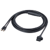
Sensor head connection cables
| Type | Appearance | Model No. | Cable length | Description |
|---|---|---|---|---|
| Sensor head connection cables |
| CN-HT-C2 | 2 m 6.562 ft | This cable is used to connect the sensor head to the controller. The cable is branched into two cables on the sensor head connecting side, but the two cables can be connected interchangeably to the emitter and receiver. |
| CN-HT-C5 | 5 m 16.404 ft | |||
| CN-HT-C10 | 10 m 32.808 ft | |||
| CN-HT-C20 | 20 m 65.617 ft |
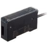
Controllers
| Type | Appearance | Model No. | Output | Maximum number of connectable controllers | |
|---|---|---|---|---|---|
| Master unit | High performance type |
| HG-TC101 | NPN open-collector transistor | Up to 15 slave units can be connected per master unit (Note) |
| HG-TC101-P | PNP open-collector transistor | ||||
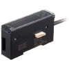
| Slave units | High performance type |
| HG-TC111 | NPN open-collector transistor | |
| HG-TC111-P | PNP open-collector transistor | ||||
| Wire-saving type |
| HG-TC113 | - | ||
Note:
When connected to a communication unit for digital displacement sensor, up to 14 slave units can be connected per master unit.
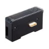
USB communication unit
| Type | Appearance | Model No. | Description |
|---|---|---|---|
| USB communication unit (Note 1) |
| SC-HG1-USB | When used together with the "HG-T Configuration Tool" USB-based PC setting software, current values and settings in the HG-T series can be confirmed or changed on the PC screen. * The USB-based PC setting software, "HG-T Configuration Tool," can be downloaded free from our website. • Communication specification: USB 2.0 Full Speed (Note 2) • Communication protocol: Proprietary protocol • USB port: USB Mini-B (1 port) • Number of connectable units Controller: Up to 15 units (1 master unit, 14 slave units) per SC-HG1-USB unit |
Notes:
1) The USB communication unit cannot be used with contact-type digital displacement sensors HG-S series.
2) Dependent on PC environment.
Communication units for digital displacement sensors
Please check each product page for communication units for Digital Displacement Sensors.
>>CC-Link IE Field / CC-Link Communication Unit
>>Communication Unit for Digital Displacement Sensors SC-HG1(for EtherCAT / RS-485)
End plates
| Type | Appearance | Model No. | Description |
|---|---|---|---|
| End plates |
| MS-DIN-E [2 pcs. per set] | Always use this when connecting controllers and a digital displacement sensor communication unit. |

System configuration
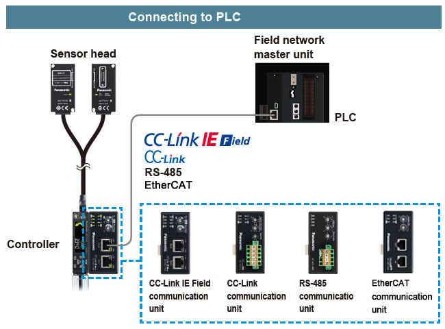
Our product lineup includes communication units compatible with a variety of field networks such as CC-Link, CC-Link IE Field and EtherCAT. They can link with a production system and enable the incorporation and utilization of IoT.
*USB communication unit and RS-485 communication unit cannot be used simultaneously.*To connect RS-485 communication unit via USB, the customer must arrange a USB2.0→RS-485 converter.
------------------------------ Tab4 showing ------------------------------
Option
| Type | Appearance | Model No. | Description |
|---|---|---|---|
| Side view attachment |
| HG-TSV10 | Designed for exclusive use with the HG-T1010 standard type sensor head. This attachment can bend the laser beam at a right angle, thus allowing flexible installation of the sensor head. Two M2 (length 4 mm 0.157 in) screws with washers are attached. * Two pieces of attachment are required when using the attachment on both emitter and receiver. * Be sure to confirm proper detection using actual equipment in advance when using the attachment. |

------------------------------ Tab5 showing ------------------------------
Specifications
Sensor heads
| Type | Measurement width 10 mm 0.394 in / Standard type | Measurement width 10 mm 0.394 in / Slim type | |
|---|---|---|---|
| Model No. | HG-T1010 | HG-T1110 | |
| Applicable regulations | CE Marking (EMC Directive, RoHS Directive), UKCA Marking (EMC Regulations, RoHS Regulations), FDA regulations | ||
| Compatible controller | HG-TC101 (-P), HG-TC111 (-P), HG-TC113 | ||
| Position detection method | CMOS-based | ||
| Installation distance | 0 to 500 mm 0 to 19.685 in [When side view attachment HG-TSV10 is attached, 0 to 100 mm 0 to 3.937 in (typical)] | ||
| Measurement width | 10 mm 0.394 in | ||
| Light source | Red semiconductor laser: Class 1 [IEC / EN / JIS / GB / KS / FDA (Note 2)] Maximum output: 0.3 mW, Peak emission wavelength: 655 nm | ||
| Repeatability (Note 3) | 1 μm 0.039 mil (Installation distance: 20 mm 0.787 in) 2.5 μm 0.098 mil (Installation distance: 100 mm 3.937 in) 5 μm 0.197 mil (Installation distance: 500 mm 19.685 in) | ||
| Linearity (Note 4) | ±0.12 % F.S. (Installation distance: 20 mm 0.787 in) ±0.28 % F.S. (Installation distance: 100 mm 3.937 in) | ||
| Minimum sensing object (Note 5) | ø0.5 mm ø0.020 in (Installation distance: 500 mm 19.685 in) | ||
| Temperature characteristics (Note 6) | ±0.03 % F.S./℃ | ||
| Operation indicator | Emitter | Laser radiation indicator (Green) | |
| Receiver | Beam axis adjustment indicator (Orange / Green), Judgment output indicator (Orange / Green) | Judgment output indicator (Orange / Green) | |
| Pollution degree | 2 | ||
| Operating altitude | 2,000 m 6,561.68 ft or less (Note 7) | ||
| Environmental resistance | Protection | IP67 (IEC) (Excluding connectors) | |
| Ambient temperature | -10 to +45 ℃ +14 to +113 ℉ (No dew condensation or icing allowed), Storage: -20 to +60 ℃ -4 to +140 ℉ | ||
| Ambient humidity | 35 to 85 % RH, Storage: 35 to 85 % RH | ||
| Ambient illuminance | Incandescent light: 5,000 lx or less at the light-receiving face (Note 8) | ||
| Insulation resistance | 20 MΩ or higher, using 250 V DC megger (between all terminals and case) | ||
| Vibration resistance | 10 to 55 Hz frequency, 1.5 mm 0.059 in double amplitude in X, Y and Z directions for two hours each | ||
| Shock resistance | 196 m/s2 acceleration in X, Y and Z directions three times each | ||
| Grounding method | Capacitor grounding | ||
| Material | Case: Die-cast aluminum, Light emitting and light receiving surfaces: Glass | ||
| Cable | 0.2 m 0.656 ft 4-core shielded cable with round connectors | ||
| Net weight | Emitter: 30 g approx., Receiver: 30 g approx. | Emitter: 30 g approx., Receiver: 25 g approx. | |
Notes:
1) Specification values are based on the digital measurement values obtained by the sensor head and controller HG-TC□. Where measurement conditions have not been specified precisely, the conditions used were as follows: ambient temperature = +20 ℃ +68 ℉, controller’s average count setting 16 times, measurement target = nontransparent knife edge, installation distance = 100 mm 3.937 in, positional condition of measurement target = Half shading at the middle position of installation distance.
2) This product complies with the FDA regulations (FDA 21 CFR 1040.10 and 1040.11) in accordance with FDA Laser Notice No. 56, except for complying with IEC 60825-1 Ed. 3.
3) This is the P-P value of digital measurement value with half shading at the middle position of the installation distance.
4) Indicates an error with the ideal straight line of digital measured values.
5) When the light is blocked at the center position of 500 mm 19.685 in installation distance.
6) When the light is half-blocked at the center position of 100 mm 3.937 in installation distance.
7) Do not use or store in an environment that has been pressurized to an air pressure higher than the atmospheric pressure at 0 m.
8) When the sampling cycle of the controller is set to "standard sampling".
Controller
| Type | Master unit | Slave unit | ||
|---|---|---|---|---|
| High performance type | High performance type | Wire-saving type | ||
| Model No. | NPN output | HG-TC101 | HG-TC111 | HG-TC113 |
| PNP output | HG-TC101-P | HG-TC111-P | ||
| Applicable regulations | CE Marking (EMC Directive, RoHS Directive), UKCA Marking (EMC Regulations, RoHS Regulations) | |||
| Compatible sensor head | HG-T1010、HG-T1110 | |||
| Number of connectable units | Up to 15 slave units can be connected to a master unit. (Note 2) | |||
| Supply voltage | 24 V DC ±10 %, including ripple 0.5 V (P-P) | |||
| Current consumption (Note 3) | 100 mA or less (when sensor head is connected) | |||
| Analog outputs (Switching type) (Note 4) | Analog voltage output | • Voltage output range: 1 to 5 V/F.S. (default value) • Linearity: ±0.05 % F.S. • Output when alarm occurs: 5.2 V • Output impedance: 100 Ω max. | - | |
| Analog current output | • Current output range: 4 to 20 mA/F.S. (default value) • Linearity: ±0.25 % F.S. • Output when alarm occurs: 0 mA • Load impedance: 250 Ω max. | |||
| Control outputs (Output 1, Output 2, Output 3) | <NPN output type> NPN open-collector transistor • Maximum sink current: 50 mA (Note 5) • Applied voltage: 30 V DC or less (between output and 0 V) • Residual voltage: 1.5 V or less (at 50 mA sink current) • Leakage current: 0.1 mA or less <PNP output type> PNP open-collector transistor • Maximum source current: 50 mA (Note 5) • Applied voltage: 30 V DC or less (between output and +V) • Residual voltage: 1.5 V or less (at 50 mA source current) • Leakage current: 0.1 mA or less | - | ||
| Short-circuit protection | Incorporated (automatic reset type) | |||
| Judgment output | N.O. / N.C. switching type | |||
| Alarm output | Open when alarm occurs | |||
| External output switching | Output 1, Output 2, and Output 3 can be switched to 3-value, 2-value, Logic, and Logic 2. | - | ||
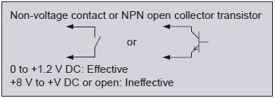
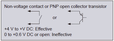
| External inputs (Input 1, Input 2, Input 3) | <NPN output type> Non-contact input or NPN open-collector transistor • Input conditions Invalid: +8 V to +V DC or open Valid: 0 to +1.2 V DC • Input impedance: 10 kΩ approx. <PNP output type> Non-contact input or PNP open-collector transistor • Input conditions Invalid: 0 to +0.6 V DC or open Valid: +4 V to +V DC • Input impedance: 10 kΩ approx. | - | ||
| Input time | • Trigger input: 2 ms or more (ON) • Laser emission stop input, preset input, reset input, bank input A/B(Note 6): 20 ms or more (ON) | |||
| External input switching | Input 1, Input 2, and Input 3 can be switched to “Preset / Reset / Trigger”, “Bank Input A / Bank Input B / Select (Preset, Reset, Trigger)”, or “Laser emission stop”. | - | ||
| Sampling cycle | 1 ms (standard sampling) / 0.5 ms (high-speed sampling) | |||
| Average count (response time) (Note 6) | 1 time (2 ms), 2 times (3 ms), 4 times (5 ms), 8 times (9 ms), 16 times (17 ms), 32 times (33 ms), 64 times (65 ms), 128 times (129 ms), 256 times (257 ms), 512 times (513 ms), and 1,024 times (1,025 ms) switching type | |||
| Display resolution | 1 μm 0.039 mil | |||
| Display range | -199.999 to 199.999 mm -7.874 to 7.874 in | |||
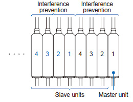
| Interference prevention function | Incorporated (Note 7) | - | ||
| Pollution degree | 2 | |||
| Operating altitude | 2,000 m 6561.68 ft or less (Note 8) | |||
| Environmental resistance | Protection | IP40(IEC) | ||
| Ambient temperature | -10 to +50 ℃ +14 to +122 ℉ (No dew condensation or icing allowed) (Note 5), Storage: -20 to +60 ℃ -4 to +140 ℉ | |||
| Ambient humidity | 35 to 85 % RH, Storage: 35 to 85 % RH | |||
| Voltage withstandability | 1,000 V AC for one minute between all supply terminals connected together and enclosure | |||
| Insulation resistance | 20 MΩ, or more, with 250 V DC megger between all supply terminals connected together and enclosure | |||
| Vibration resistance | 10 to 150 Hz frequency, 0.75 mm 0.030 in double amplitude (10 to 58 Hz), Maximum acceleration 49 m/s2 (58 to 150 Hz) in X, Y and Z directions for two hours each | |||
| Shock resistance | 98m/s2 acceleration (10 G approx.) in X, Y and Z directions five times each | |||
| Material | Case: Polycarbonate, Cover: Polycarbonate, Switches: Polyacetal | |||
| Cable | 0.2 mm2 2-core (brown and blue lead wires) / 0.15 mm2 7-core composite cable, 2 m 6.562 ft long | 0.15 mm2 7-core composite cable, 2 m 6.562 ft long | - | |
| Net weight | 140 g approx. | 140 g approx. | 60 g approx. | |
Notes:
1) Where measurement conditions have not been specified precisely, the conditions used were as follows: supply voltage +24 V DC, ambient temperature +20 ℃ +68 ℉.
2) When connected to a communication unit for digital displacement sensor, up to 14 slave units can be connected per master unit.
3) Current consumption does not include analog current output.
4) Linearity is a value calculated from digitally measured values at F.S. = 16 mA for current output or F.S. = 4 V for voltage output.
5) When slave units are connected to the master unit, the maximum sink current / source current of control output and ambient temperature vary depending on the number of connected slave units as shown below.
| Number of connected slave units | Maximum sink current and source current of control output | Ambient temperature | |
|---|---|---|---|
| When communication unit is connected | |||
| 1 to 7 units | 1 to 6 units | 20 mA | -10 to +45 ℃ +14 to +113 ℉ |
| 8 to 15 units | 7 to 14 units | 10 mA | |
6) Average count (response time) is for when the sampling cycle is set to 1 ms (standard sampling). Response times differ when the sampling cycle is set to 0.5 ms (high-speed sampling).
7) This function operates for each set of 4 connected controllers.
8) Do not use or store in an environment that has been pressurized to an air pressure higher than the atmospheric pressure at 0 m.
HG-T series' self-monitoring function
| Status | Response parameter | Measures | Controller HG-TC□ | |
|---|---|---|---|---|
| Error code (Note 1) | Measurement alarm (Note 1) | |||
| Notification | Sensor head unconnected | Status check | E200 | — |
| Connected sensor head incompatible | Status check | E230 | — | |
| Connected unit count check error | Status check | E160 (For master units only) | — | |
| NPN / PNP output type mixture error | Status check | E100 (For master units only) | — | |
| Calculated unlit count error | Status check | E110 (For master units only) | — | |
| Copy executionerror (Slave unit problem) | Status check | E170 (For master units only) | — | |
| Detection capability limit (obtained edge information) (Note 2) | Sensing object check | — | Measurement alarm 1 | |
| The amount of entering light is too much due to the influences of ambient light, etc. (Note 2) | Status check | — | Measurement alarm 1 | |
| The amount of entering light decreases due to stain on the detection surface, beam axis misalignment, etc. | Sensing object check | — | Measurement alarm 2 | |
| The specified measurement direction differs from the insertion direction of the detected object. | Status check / Sensing object check | — | Measurement alarm 2 | |
| Caution | Controller cumulative run time exceeded (87,600 hours) | Controller replacement | — | — |
| Sensor head cumulative run time exceeded (87,600 hours) | Sensor head replacement | — | — | |
| Controller memory saving count exceeded (1,000,000 times) | Controller replacement | — | — | |
| Sensor head memory saving count exceeded (for receivers only, 1,000,000 times) | Sensor head replacement | — | — | |
| Fault | Controller memory function damaged | Controller replacement | E600 | — |
| E610 | ||||
| E620 | ||||
| Sensor head memory function damaged | Sensor head replacement | E630(For receivers only) E640(For emitters only) | — | |
| Output section short-circuit error | Status check / Replacement | E700 | — | |
| Detection circuit damaged | Sensor head replacement | E240 | — | |
| System error | Controller replacement | E900 | — | |
| E910 | ||||
| E911 | ||||
| E912 | ||||
| E920 | ||||
Notes:
1) Error codes and alarms are displayed on HG-TC□ controllers.
2) If "Alarm condition selection (ALM.CND)" is set to "Hold last value (HOLD)", Measurement alarm 1 is not notified.
Communication units for digital displacement sensors
| Designation | USB communication unit | |
|---|---|---|
| Model No. | SC-HG1-USB | |
| Applicable regulations | CE Marking (EMC Directive, RoHS Directive), UKCA Marking (EMC Regulations, RoHS Regulations) | |
| Compatible controllers | HG-TC□ | |
| Maximum number of connectable controllers | Maximum of 15 controllers (one master, 14 slaves) per SC‑HG1‑USB unit | |
| Supply voltage (Note 2) | 24 V DC ±10 %, Ripple (P-P) 10 % or less (Within specified power supply voltage range) | |
| Current consumption | 50 mA or less | |
| Communication method | USB 2.0 Full Speed (Note 3) | |
| Communication protocol | Our dedicated protocol | |
| USB port | USB Mini-B (1 port) (Note 4) | |
| Pollution degree | 2 | |
| Operating altitude | 2,000 m 6561.680 ft or less (Note 5) | |
| Environmental resistance | Protection | IP40 (IEC) |
| Ambient temperature | -10 to +45 ℃ +14 to +113 ℉ (No dew condensation or icing allowed), Storage: -20 to +60 ℃ -4 to +140 ℉ | |
| Ambient humidity | 35 to 85 % RH, Storage: 35 to 85 % RH | |
| Voltage withstandability | 1,000 V AC for one min. between all supply terminals connected together and enclosure | |
| Insulation resistance | 20 MΩ or more, with 250 V DC megger | |
| Vibration resistance | 10 to 150 Hz frequency, 0.75 mm 0.030 in double amplitude (10 to 58 Hz), Maximum acceleration 49 m/s2 (58 to 150 Hz) in X, Y and Z directions for two hours each | |
| Shock resistance | 98 m/s2 acceleration (10 G approx.) in X, Y and Z directions five times each | |
| Material | Enclosure: Polycarbonate | |
| Weight | Net weight: 35 g approx., Gross weight: 95 g approx | |
Notes:
1) Where measurement conditions have not been specified precisely, the conditions used were an ambient temperature of +20 ℃ +68 ℉.
2) Power is supplied from a connected controller / master unit.
3) Dependent on PC environment.
4) USB 2.0 (Mini-B) cable for the connection of a PC is not provided with the product.
Please purchase a USB 2.0 (Mini-B) cable.
5) Do not use or store in an environment that has been pressurized to an air pressure higher than the atmospheric pressure at 0 m.
Please check each product page for other communication units.
>>CC-Link IE Field / CC-Link Communication Unit
>>Communication Unit for Digital Displacement Sensors SC-HG1
------------------------------ Tab6 showing ------------------------------
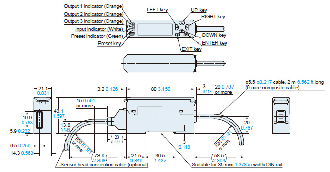
Dimensions
- Unit: mm in
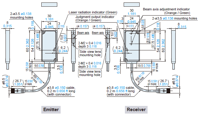
HG-T1010
Sensor head (Standard type)
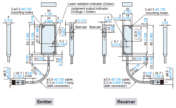
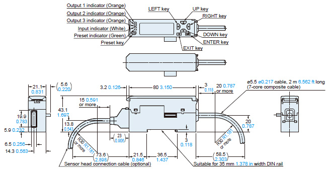
HG-T1110
Sensor head (Slim type)
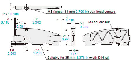
HG-TSV10
Side view attachment (Optional)
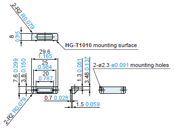
Two M2 (length 4 mm0.157 in) screws with washers are attached.
Assembly dimensions
The diagram shows the attachment mounted on the receiver of the standard type sensor head HG-T1010.
Can be installed in either direction.
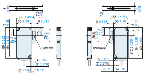
Notes:1)The attachment cannot be installed to the slim type sensor head HG-T1110.2)Be sure to confirm proper detection using actual equipment in advance when using the attachment.
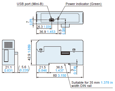
HG-TC101
HG-TC101-P
Controller (Master unit)
HG-TC111
HG-TC111-P
Controller (Slave unit)
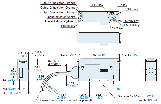
HG-TC113
Controller (Slave unit)
CN-HT-C□
Sensor head connection cable
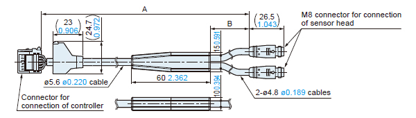
| Model | A | B |
|---|---|---|
| CN-HT-C2 | 2,000 78.740 | 500 19.685 |
| CN-HT-C5 | 5,000 196.850 | 500 19.685 |
| CN-HT-C10 | 10,000 393.701 | 1,000 39.370 |
| CN-HT-C20 | 20,000 787.402 | 1,000 39.370 |
SC-HG1-USB
USB communication unit
Communication unit
Please check each dimensions page for communication units for Digital Displacement Sensors.
>>CC-Link IE Field / CC-Link Communication unit Dimensions
>>Communication Unit for Digital Displacement sensor SC-HG1 Dimensions
MS-DIN-E
End plate (Optional)
Material: Polycarbonate
------------------------------ Tab7 showing ------------------------------


------------------------------ Tab8 showing ------------------------------
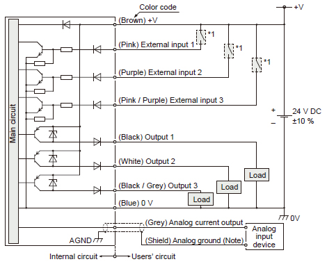
I/O Circuit and Wiring diagrams
NPN output type
HG-TC101 / Master unit
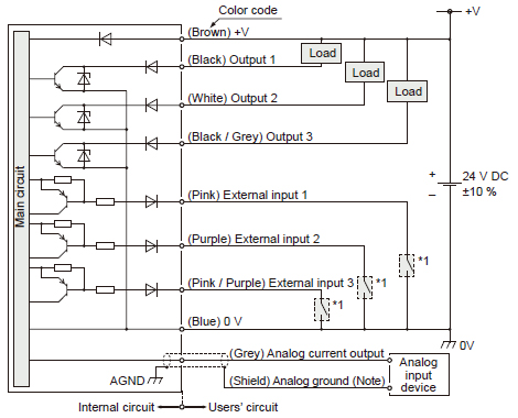
HG-TC111 / Slave unit
* 1
Note: Use shielded wire for the analog output.
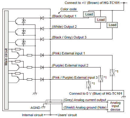
PNP output type
HG-TC101-P / Master unit
HG-TC111-P / Slave unit
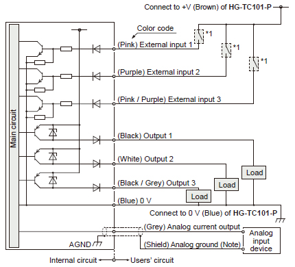
* 1
Note: Use shielded wire for the analog output.
------------------------------ Tab9 showing ------------------------------
- This product is a class 1 laser product according to IEC/EN/JIS/GB/KS standards and FDA regulations *.
- Avoid observing beams in a dark surrounding environment.
- Do not look at beams using an optical device such as an optical telephoto system.
- The following label is affixed to the emitter of this product. Handle the product according to the instruction given on the label.

This product complies with the FDA regulations (FDA 21 CFR 1040.10 and 1040.11) in accordance with FDA Laser Notice No. 56, except for complying with IEC 60825-1 Ed. 3.
Safety standards for laser beam products
IEC : IEC 60825-1:2014 EN : EN 60825-1:2014/A11:2021 JIS : JIS C 6802:2014 GB : GB 7247.1-2012 KS : KS C IEC 60825-1:2014 FDA : PART 1040.10, 1040.11(Laser Notice No.56 applied)These standards classifies laser products according to the level of hazard and provide the safety measures for respective classes. Based on the above standards, the HG-T series is classified as a Class 1 laser product.
| Classification | Description |
|---|---|
| Class 1 | Lasers that are safe under reasonably foreseeable conditions of operation, including the use of optical instruments for intrabeam viewing. |
Note: When an unexpected failure occurs, dangerous radiation may be generated. Therefore, pay special attention to safety.
- For the purpose of preventing any injury which may occur to the user by the use of the laser product in advance, the following standards have been established by the IEC Standards, EN Standards, JIS Standards, GB Standards, KS Standards and FDA Regulations.
Safe use of laser products
- For the purpose of preventing users from suffering injuries by laser products, each standard stipulates (Safety of laser products).Kindly check the standards before use.
With regards to the connected use of HG-S and HG-T
Please refer to the page below when using HG-S controllers and HG-T controllers connected.
>>With regards to the connected use of HG-S and HG-T
![]()
[Sensor head] Mounting
・The light emitting and receiving surfaces of the sensor head must be free of water, oil, fingerprints, and other substances that refract light as well as dust, grit, and other objects that intercept light.
・Do not allow ambient light such as sunlight to directly hit the light receiving section of the sensor head. In particular, if precision is required, use this product by mounting a douser (or similar material) on the sensor head.
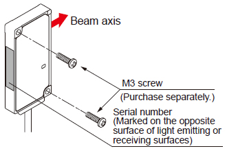
・A serial number is marked on each opposite surface of the light emitting and receiving surfaces of the sensor head. Use a pair of emitter and receiver that have the same serial number.
- For the installation of sensor heads, use M3 screws and tighten to the torque of 0.5 N·m. M3 screws are not provided with the product.
[Controller] Mounting
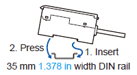
Mounting
1. Insert the rear of the mounting part into the DIN rail.
2. While pressing down on the rear of the mounting part, insert the front of the mounting part into the DIN rail.
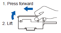
Removal method
1. Grasp the product and push forward.
2. Lift the front to remove.
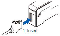
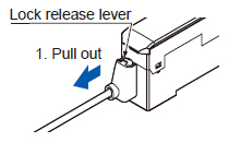
Attaching the sensor head connection cable
Mounting
1. Insert the sensor head connection cable into the connector for the sensor head connection cable on the controller.
Removal method
1. Grasp the controller, and while pressing on the lock release lever on the connector of the sensor head connection cable, pull toward you to disconnect.
Note:
If you attempt to disconnect the cable by pulling it without pressing the lock release lever, cable wire breakage and connector damage may occur.
[Controller] Connection
・Always shut off the power before connecting a slave unit to or disconnecting a slave unit from the master unit. Risk of controller damage if you attempt connection with the power on.
・Insert the male connector firmly into the female connector. Risk of controller damage if not completely connected.
・When connecting slave units to a master unit, connect only NPN output types, or only PNP output types.
Dissimilar output types cannot be connected together.
・To connect units, the units must be mounted on a DIN rail. Attach end plates MS-DIN-E (optional) so as to enclose the connected units at the ends.
- If the HG‑TC□ controller is used together with the HG‑SC□ controller for contact-type digital displacement sensor HG-S series, make sure to use the HG-SC□ controller manufactured in or after February, 2019.
Furthermore, connect the slaves units of the same series to the side closer to the master unit and the slave units of the other series to the far side.
[Common] Wiring
・The product is designed to fulfill the specifications when combined with the HG-T□ sensor head and HG-TC□ controller. If the product is used in combination with other products, it not only fails to meet the specifications but also generates a malfunction in some cases.
・For the controller DC power supply, only use a power supply that is isolated by means of an isolation transformer or otherwise.
・Risk of short-circuiting and damage to the controller or power supply if a transformer such as an auto transformer is used. Risk of short-circuiting and damage to the controller or power supply if incorrectly mounted or connected.
- Make sure that the power supply is off while performing wiring or expansion work.
- After you have completed wiring work, check the wiring carefully before switching on the power.
- Do not run the wires together with high-voltage lines or power lines or put them in the same raceway. This can cause malfunction due to induction.
- Verify that the supply voltage variation is within the rating.
- If power is supplied from a commercial switching regulator, ensure that the frame ground (F.G.) terminal of the power supply is connected to an actual ground.
- Make sure that stress by forcible bend or pulling is not applied directly to the sensor cable joint.
[Common] Others
- This device has been developed / produced for industrial use only.
- Do not use this product outside the range of the specifications. Risk of an accident and product damage. There is also a risk of a noticeable reduction of service life.
- Do not use during the initial transient time after the power supply is switched on.
- To ensure performance, use the product at least 30 minutes (warm-up time) after the power is turned ON.
- This product (controller and sensor head receiver) uses an EEPROM. The EEPROM has a service life of one million setting operations.
- This product is suitable for indoor use only.
- Avoid dust, dirt, and steam.
- Take care that the product does not come in direct contact with organic solvents such as thinner.
- Take care that the product does not come in direct contact with strong acid or alkaline.
- Take care that the product does not come in direct contact with oil or grease.
- Do not use in an environment containing inflammable or explosive gases.
- Performance may not be satisfactory in a strong electromagnetic field.
- The sensor head is watertight, but the connector is not dustproof, waterproofing, or corrosion-resistant due to its structural reasons, so measurements cannot be taken under the water or in the rain. Pay attention to the environment where the product is used.
- This product is a precision device. Do not drop or otherwise subject to shock. Risk of product damage.
- Never attempt to disassemble, repair, or modify the product.