Basic Information
Connect Fiber Sensors and Displacement
Sensors to CC-Link IE Field for High-Speed Control


Features
Introducing the industry's first* communication units compatible with CC-Link IE Field
* As of March 2017, in-company survey

Visualize collected sensor data to launch IoT initiatives!
Conditions surrounding the manufacturing industry are rapidly changing as production processes are advancing dramatically based on keywords such as IoT and Industry 4.0. To respond to the IoT trend, "visualization" is the first step to take. Panasonic Industry offers sensors and communication units that achieve the acquisition and visualization of sensor data.
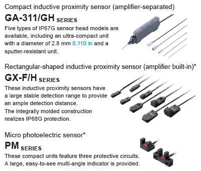
Connection of various sensors to the network
Each SC-GU3 series unit can be connected with up to 16 sensors*.
* Up to 12 units when the system is configured with FX-500 / LS-500 series

* CC-Link IE Field and CC-Link are trademarks of Mitsubishi Electric Corporation, and are controlled by the CC-Link Partner Association.
Transmission of digital (numerical) data from pressure sensors, fiber sensors, laser sensors, displacement sensors, and the like to the network
Setting of sensor threshold values and operation / confirmation of current values can be performed on the network. This eliminates the need to directly operating individual sensor units.

Transmission of ON/OFF data of proximity sensors and micro photoelectric sensors to the network
The ON/OFF data of sensors can be centrally managed on the network. Should an abnormality occur, the problem cause can be easily identified and located.
* SC-E1 1-channel connector input extension unit or SC-E81 / SC-E82 8-channel connector input extension unit is also required.
Communication unit for direct connection of sensors to the network!
Use of the communication unit enables the connection of various Panasonic Industry sensors to a CC-Link network for the real-time acquisition of digital data and ON/OFF data. This allows you to change sensor settings via the network and also log data for predictive maintenance purposes.

Connection of displacement sensors to the network
Each SC-HG1 series unit can be connected with up to 15 displacement sensors.

Transmission of digital (numerical) data from digital displacement sensors to the network
The SC-HG1 series achieves programless transmission of high-precision data.
Internal settings of multiple units can also be changed in a batch via the network.

Compatible with self-monitoring function that is ideal for production lines
The HG-S / HG-T series with a self-monitoring function diagnoses its own state and notifies when readjustment of settings / setup is required or when maintenance is needed.
For more details, please refer to the catalogs of the HG-S / HG-T series.
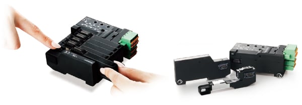
Batch saving of sensor settings at equipment startup!


Easy replacement of a sensor without separating the adjacent sensor amplifier
Sensors are detachable simply by pushing down the lever of cascading connector unit and sliding the sensor amplifier sideways.
* SC-GU3 series
Support for Mitsubishi Electric’s iQ Sensor Solution
The SC-GU3-01 and SC-HG1-C Communication Units for CC-Link are compatible with Mitsubishi Electric's iQ Sensor Solution (iQSS) and can be used in combination with products that support iQSS, for example Mitsubishi Electric's MELSEC series.

Digital sensors connected to SC-GU3-01 / SC-HG1-C can be operated using Mitsubishi Electric’s iQ Works (GX Works) software. The following functionality is supported by using iQ Works to load CSP+ data.
(Note) CSP+: CC-Link family system profile
[1]CC-Link configuration information can be used to easily check the configuration of devices (sensor types: fiber, pressure, cascading configuration, number of units) connected to SC-GU3-01 / SC-HG1-C.
[2]A list of sensor-specific parameter data (write / read) can be acquired and changed.
[3]Allocation of the devices connected to SC-GU3-01 / SC-HG1-C can be displayed by loading CSP+ data.
* The confirmation process of the specifications and user manual for SC-GU3-01 / SC-HG1-C can be significantly reduced.
* You can perform functions such as “easy startup,” “sensor monitoring,” “parameter read/write,” “backup/restore,” and more. Requires Mitsubishi Electric’s GX Works 2 sequencer engineering software Ver. 1.492 or later.

Order guide
SC-GU3-0□
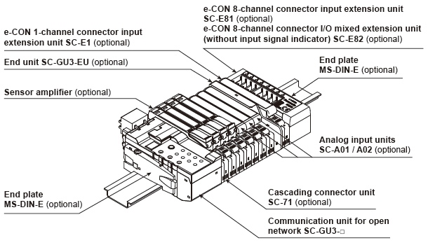
Example of system configuration
When optical communication is used in a system connected with product models not compatible with optical communication, connect the incompatible units after the SC-GU3-EU.
A maximum of 12 units can be connected if the system is connected with a FX-500 / LS-500 series unit.
A maximum of 16 sensor amplifiers can be connected.
Communication units
| Designation | Appearance | Model No. | Descritption |
|---|---|---|---|
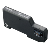
| Communication unit for CC-Link IE Field |
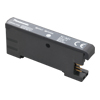
| SC-GU3-04 | This is a communication unit, which can convert the output signal of a sensor amplifier into communication data for CC-Link IE Field. |
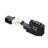
| Communication unit for CC-Link |
| SC-GU3-01 | This is a communication unit, which can convert the output signal of a sensor amplifier into communication data for CC-Link. |


Others
| Designation | Appearance | Model No. | Descritption |
|---|---|---|---|
| End unit |
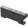
| SC-GU3-EU | This end unit can change and check the settings of sensor amplifiers that allow optical communication and monitor operation status. |
| Cascading connector unit |
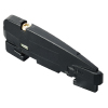
| SC-71 | This one-touch connector is used to connect the following devices to SC-GU3-0□: The FX-500/550/410/300/311 fiber sensor, the LS-500/400 laser sensor, the DPS-400 digital pressure sensor, SC-E1, SC-A01 and SC-A02, etc. |
| e-CON 1-channel connector input extension unit |
| SC-E1 | This extension unit can be connected to commercially available devices (Note) including an NPN output type or DC 2-wire type sensor. Includes power and input signal indicators (for one channel). When using in combination with the SC-GU3 series, use with the SC-71. |
| e-CON 8-channel connector input extension unit |
| SC-E81 | This extension unit can be connected to eight NPN output type devices. Includes power and input signal indicators (for eight channels). |
| e-CON 8-channel connector input extension unit |
| SC-E82 | This extension unit can be connected to eight NPN output type devices. Includes a power indicator. (Does not include an input signal indicator) |
| Analog voltage input unit |
| SC-A01 | This extension unit can be connected to NPN output type devices or analog voltage output type devices. When using in combination with the SC-GU3 series, use with the SC-71. |
| Analog current input unit |
| SC-A02 | This extension unit can be connected to NPN output type devices or analog voltage output type devices. When using in combination with the SC-GU3 series, use with the SC-71. |
| End plate |
| MS-DIN-E | After SC-GU3-0□, a sensor amplifier, an analog input unit or an end unit are connected on a DIN rail, make sure to install the end plates in such a way that they hold the unit in place at both ends. [Two pcs. per set] |

Note:
Conditions of connectable DC 2-wire type input device
・Leak current: 1 mA or less (when the power is OFF), Offset voltage: 3 V or less (when the power is ON)
・Product whose load current range includes 5 to 8 mA
SC-HG1-□
Example of system configuration

| Designation | Appearance | Model No. | Description |
|---|---|---|---|
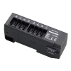
| CC-Link IE Field communication unit for digital displacement sensor |
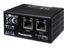
| SC-HG1-CEF | This communication unit converts the output data from digital displacement sensors to data that can be communicated via CC-Link IE Field. |
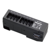
| CC-Link communication unit for digital displacement sensor |
| SC-HG1-C | This communication unit converts the output data from digital displacement sensors to data that can be communicated via CC-Link. |
| End plate |
| MS-DIN-E | After a communication unit and controllers are connected on a DIN rail, make sure to install the end plates in such a way that they hold the unit in place at both ends. [Two pcs. per set] |
Option
For SC-GU3-□
| Designation | Appearance | Model No. | Descritption |
|---|---|---|---|
| Cable with connector on one end |
| CN-M20-C2 | This cable has a connector for linking to the parallel output signal. |

Discontinued products [Order accepted till September, 2024]

Specifications
Refer to "Communication Unit for Open Network SC-GU3" and "Communication Unit for Digital Displacement Sensors SC-HG1" for the specifications.
Models that can be connected to the SC-GU3-0□
(Use in combination with SC-71, with the exception of certain models)
| Communication compatibility | Type | Model No. |
|---|---|---|
| Models that support optical communications | Digital fiber sensors (NPN output type) | FX-501, FX-502 |
| Digital laser sensors (NPN output type) | LS-403, LS-501 | |
| Digital pressure sensors (NPN output type) | DPS-401, DPS-402 | |
| Analog input units | SC-A01, SC-A02 | |
| No optical communications | Digital fiber sensors | FX-551,FX-301(B/G/H) |
| Digital fiber sensors for manual setting | FX-411,FX-412,FX-311 (B/G) | |
| Digital fiber sensors for leak / liquid fiber | FX-301-F,FX-301-F7 | |
| Digital laser sensors | LS-401 | |
| Compact inductive proximity sensors | GA-311 | |
| 1-channel connector input extension unit | SC-E1 ,SC-T1J | |
| 8-channel connector input extension unit | SC-E81 | |
| 8-channel connector input extension unit (without an input signal indicator) | SC-E82 |


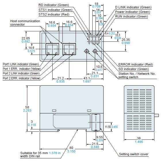
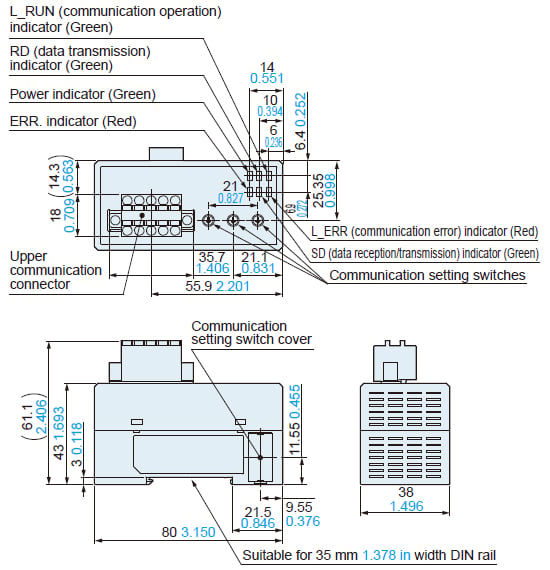
Dimensions
Unit: mm in
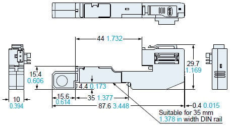
SC-GU3-04
Communication unit for CC-Link IE Field
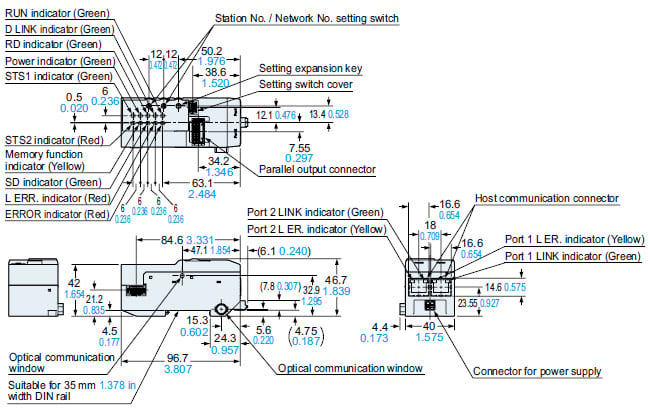
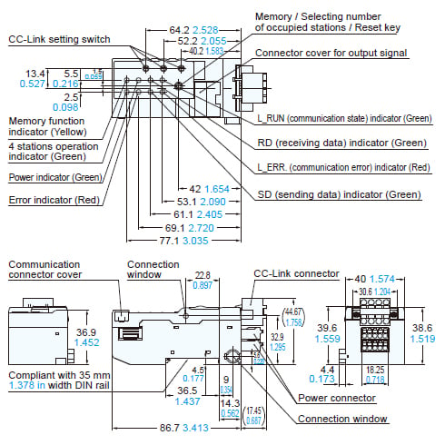
SC-GU3-01
Communication unit for CC-Link
SC-GU3-EU
End unit
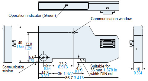
SC-71
Cascading connector unit
SC-E1
e-CON 1-channel connector input extension unit
SC-E81 / SC-E82
e-CON 8-channel connector input extension unit
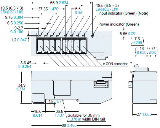
* SC-E82 is not equipped with an input indicator.
SC-A01 / SC-A02
Analog input unit
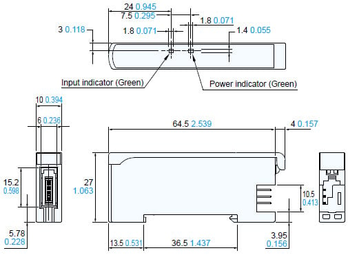
SC-HG1-CEF
Communication unit for CC-Link IE Field
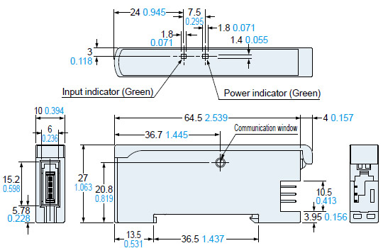
SC-HG1-C
Communication unit for CC-Link
MS-DIN-E
End unit
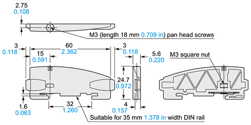
Material:Polycarbonate
Software
Computer software for SC-GU3-04 / SC-GU3-01 compatible with Mitsubishi Electric’s EZSocket
By using the SC-PC1 PC software setting, communication commands can be transmitted via the MELSEC series for the ladderless manipulation of information (including sensor data) for the SC-GU3-04 / SC-GU3-01 units connected to CC-Link.
SC-PC1 : [Order end date] September 30, 2024

* iQ Works, CC-Link, CC-Link IE Field, iQ Sensor Solution and EZSocket are registered trademarks of Mitsubishi Electric Corporation.
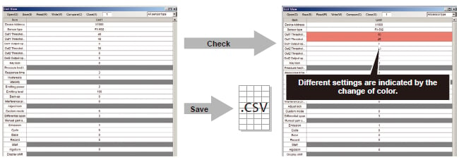
Sensor settings backup
The SC-PC1 software can load sensor settings information. * The loaded data can be saved in the CSV format.
Furthermore, cross-checking with the settings data of sensors connected to the SC-PC1 is possible.
This function is useful when you want to store the sensor settings data before sending out the devices or when you want to check the sensor settings in the event a problem occurs.
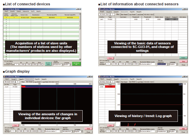
Sample program for the display of data for when using PLC and display device
The sample program enables the monitoring of digital sensors, such as incident light intensity and pressure, as well as the writing of data for the change of sensor settings.
The sample program (display screen, ladder) includes a process for the confirmation of threshold values / displayed values and the basic settings for sensor amplifiers. It facilitates the development of original programs. The display language of the sample program can be switched to Japanese or English.

Sample program for the SC-GU3-01 Communication Unit for CC-Link
Setting screen

*: The screen image is of the GOT1000 series manufactured by Mitsubishi Electric Corporation.
| Display | Sequencer | Free downloads |
|---|---|---|
| GOT1000 series (Mitsubishi Electric Corporation) | Mitsubishi Electric Corporation MELSEC-Q series MELSEC-L series | Available for download from the Mitsubishi Electric and Panasonic Industry websites |
| GOT2000 series (Mitsubishi Electric Corporation) | Mitsubishi Electric Corporation MELSEC iQ-R series | Available for download from the Panasonic Industry website |
With regards to the connected use of HG-S and HG-T
Please refer to the page below when using HG-S controllers and HG-T controllers connected.
>>With regards to the connected use of HG-S and HG-T![]()