Basic Information
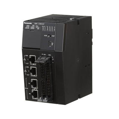
PLC + Motion + Communication 【All-in-one】


UL , CE , Korean KC , UKCA: Marking conformity
Korean KC: PNP type complies from May 2024 production lot.
Features
PLC + Motion + Communication
Integrate PLC and motion
High speed motion control Fastest cycle 500 μs
Multitask control by function aggregation

Motion control
- Positioning / Speed control / Torque control
- Cam synchronization, Gear synchronization, CNC control
Multitask control
- High speed motion control
- Display / Device / Upper communication
- Data processing

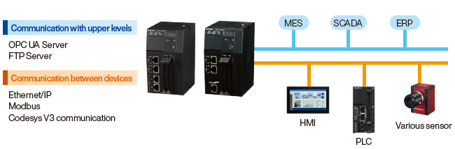
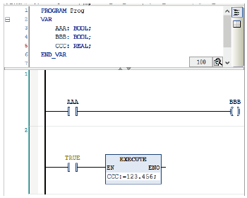
A CODESYS‑based integrated development environment that centralizes and streamlines application development.
Supports LD, ST, FBD, SFC, IL, and CFC languages for flexible programming.
Compliant with international standards IEC 61131‑3 and IEC-61131-10. 
Improves development efficiency through program reuse and asset management.

*It can be downloaded free of charge from our website.
Enhanced communication between the upper level and the device
Supports various network protocols
Motion
Cam synchronous control expanded so that anyone can use it
Extended cam editor [Ver.1.4 Additional Features]
Create cam waveforms more easily by intuitively editing graphs and numerically editing sections.

Supports multiple types of cam waveforms [Ver.1.4 Additional Features]
You can freely draw a cam waveform using a generic cam curve.
Applies to applications using dedicated cam curves.

Function blocks optimized for each application
Floating Trapezoid [Patent pending][Ver.1.4 Additional Features]
It combines the versatility of a trapezoid with the connectivity of a quintic curve. You can create cam waveforms that suppress rapid acceleration and deceleration.


Rotary cutter
In packaging machines and cutting machines, it is possible to perform cutting operations that synchronize the speed of the cutter blade with the feed direction of the product. The cut surface is cleaner than the cutting method with constant circumferential speed.

Expanding CNC synchronous control so that anyone can use it
CNC program editor
You can easily create a program for the first time because you can check the trajectory while writing the program.

Supports various CNC programs
2-axis, 3-axis linear (circular) interpolation
Move from current coordinates to target coordinates by linear (circular) interpolation

Coordinate transformation

Work and tool coordinates are also supported.
Smooth the path, add R to the path

Path connections can be changed to smooth trajectories.
Iterative processing

Possible to repeat by incrementing the counter or by conditional branching.
Change of machining plane, coordinate transformation

Set the plane on which circular interpolation will be performed. 3D processing is also applicable.
Tool diameter compensation

Correction is performed at the specified distance inside and outside the rectangle.
Tool length compensation

Correct the path according to the tool length used.
H-switch function

This function allows you to turn the IO output ON/OFF when the interpolation movement distance reaches a predetermined amount.
Subprograms

Programs can be modularized.
Achieve object-oriented programming
- Divided implementation by POU (program configuration unit)
- Program part, function part (FB, FUN), variable definition part (structure, enumeration, union)
- FB methods and inheritance (equivalent to class concept), interfaces available
- Realization of componentization by library function
Sample image of modularization and structuring
Realization of highly readable programs through modularization and structuring.
Contributes to reducing design man-hours as it is easy to reuse designs.

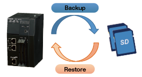
Project data management is possible
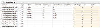
Recipe manager function
- -Management of product type data
- -Backup / restore of retained data
Project management function
- -Operation of the main unit or program (FB)
- -Project backup to SD
- -Project restore from SD
Easily program MQTT clients compatible with PubSub model [Ver.1.4 Additional Features]
By building an asynchronous communication system, it is possible to add or reduce equipment while the site is in operation.

Also supports FTP server, DNS, and SNTP connections.
Compliance with international standards

| Conformed standards | Standard number | |
|---|---|---|
| EU/UK Standards | EMC | EN 61131-2 |
| RoHS | EN IEC 63000 | |
| UL Standards | UL61010-1, UL61010-2-201 | |
| CSA Standards | C22.2 No.61010-1-12, C22.2 No.61010-2-201 | |
| Radio Waves Act (South Korea) (KC) | KS C IEC 61131-2 | |
EMC : Electromagnetic Compatibility
RoHS : Restriction of Hazardous Substances
IEC : International Electrotechnical Commission
EN : Europaischen Norman
UL : Underwriters Laboratories
CSA : Canadian Standards Association
KC : Radio Waves Act (South Korea)
The motion controller is a Class A device (commercial broadcasting communication device) under Radio Waves Act(South Korea).
Please use this product after recognizing the following precautions.

System Configuration

* Realtime Express and RTEX are registered trademarks of Panasonic Holdings Corporation.
Realtime Express is a high-speed and synchronous motion network exclusively developed by our company.
* EtherCAT is a registered trademark of patented technology licensed from Beckhoff Automation GmbH in Germany.
Specifications
- Common Specifications
- GM1 Controller
- Digital input unit
- Digital output unit
- Digital input / output unit
- Analog input unit
- Analog output unit
- Pulse output unit
- Serial Communication Unit
Common Specifications
| Item | Specifications |
|---|---|
| Rated voltage | 24 V DC |
| Operating voltage range | 20.4 to 28.8 V DC |
| Allowable momentary power failure time | 24 V DC 10 ms or less (at Product shipment) |
| Operating ambient temperature | 0 to +55 ℃ |
| Storage ambient temperature | -40 to +70 ℃ |
| Operating ambient humidity | 10 to 95 % RH (at +25 ℃, no condensation or icing) |
| Storage ambient humidity | 10 to 95 % RH (at +25 ℃, no condensation or icing) |
| Dielectric strength (Leakage current: 5 mA) | 500 V AC for one minute (Note 1) |
| Insulation resistance (Test voltage: 500 V DC) | 100 MΩ or more (Note 1) |
| Vibration resistance | Compliant with JIS B 3502, IEC 61131-2 5 to 8.4 Hz, half amplitude 3.5 mm, 8.4 to 150 Hz acceleration 9.8 m/s2 10 sweeps each in X, Y and Z directions (1 octave/min) |
| Shock resistance | Compliant with JIS B 3502, IEC 61131-2 147 m/s2, 3 times each in the X, Y, Z directions |
| Noise resistance | 1000 V [p-p] with pulse widths of 1 μs and 50 ns (using a noise simulator) (Power supply terminal) |
| Atmosphere | Free of corrosive gases No excessive dust |
| European EU Standards | EMC: EN 61131-2 RoHS: EN IEC 63000 |
| Overvoltage category | Category II or less |
| Pollution degree | 2 or less |
(Note 1) Please refer to the unit's specification sheet for details of breakdown voltage and insulation resistance.
List of weights (main units)
| Unit type | Weight (main unit) | |
|---|---|---|
| GM1 Controller RTEX type | AGM1CSRX16T | Approx. 370 g (including the terminal block and end cover) |
| GM1 Controller EtherCAT type | AGM1CSEC16T | Approx. 370 g (including the terminal block and end cover) |
| AGM1CSEC16P | Approx. 370 g (including the terminal block and end cover) | |
| GM1P Controller EtherCAT type | AGM1CEEC008T | Approx. 370 g (including the terminal block and end cover) |
| AGM1CEEC032T | Approx. 370 g (including the terminal block and end cover) | |
| AGM1CEEC064T | Approx. 370 g (including the terminal block and end cover) | |
| AGM1CEEC008P | Approx. 370 g (including the terminal block and end cover) | |
| AGM1CEEC032P | Approx. 370 g (including the terminal block and end cover) | |
| AGM1CEEC064P | Approx. 370 g (including the terminal block and end cover) | |
| GM1 Digital input / output unit | AGM1X64D2 | Approx. 160 g (including the terminal block) |
| AGM1Y64T | Approx. 160 g (including the terminal block) | |
| AGM1Y64P | Approx. 160 g (including the terminal block) | |
| AGM1XY64D2T | Approx. 160 g (including the terminal block) | |
| AGM1XY64D2P | Approx. 160 g (including the terminal block) | |
| GM1 Analog input / output unit | AGM1AD8 | Approx. 150 g (including the terminal block) |
| AGM1DA4 | Approx. 150 g (including the terminal block) | |
| GM1 Pulse output unit | AGM1PG04T | Approx. 160 g (including the terminal block) |
| AGM1PG04L | Approx. 160 g (including the terminal block) | |
| GM1 Serial Communication Unit | AGM1NSCS2 | Approx. 150 g (including the terminal block) |
| AGM1NSCM2 | Approx. 150 g (including the terminal block) | |
| AGM1NSCS1M1 | Approx. 150 g (including the terminal block) | |
List of consumption current
| Unit type | Consumption current | |
|---|---|---|
| GM1 Controller RTEX type | AGM1CSRX16T | 400 mA or less |
| GM1 Controller EtherCAT type | AGM1CSEC16T | 400 mA or less |
| AGM1CSEC16P | 400 mA or less | |
| GM1P Controller EtherCAT type | AGM1CEEC008T | 400 mA or less |
| AGM1CEEC032T | 400 mA or less | |
| AGM1CEEC064T | 400 mA or less | |
| AGM1CEEC008P | 400 mA or less | |
| AGM1CEEC032P | 400 mA or less | |
| AGM1CEEC064P | 400 mA or less | |
| GM1 Digital input / output unit | AGM1X64D2 | 90 mA or less (*1) |
| AGM1Y64T | 160 mA or less (*1) | |
| AGM1Y64P | 160 mA or less (*1) | |
| AGM1XY64D2T | 120 mA or less (*1) | |
| AGM1XY64D2P | 120 mA or less (*1) | |
| GM1 Analog input / output unit | AGM1AD8 | 160 mA or less (*1) |
| AGM1DA4 | 320 mA or less (*1) | |
| GM1 Pulse output unit | AGM1PG04T | 120 mA or less (*1) |
| AGM1PG04L | 120 mA or less (*1) | |
| GM1 Serial Communication Unit | AGM1NSCS2 | 120 mA or less (*1) |
| AGM1NSCM2 | 140 mA or less (*1) | |
| AGM1NSCS1M1 | 130 mA or less (*1) | |
(*1) This is the increase in the current consumption of the controller. (Operating voltage range: 20.4 - 28.8 V)
GM1 Controller
Specifications of the USB Port
| Item | Specifications |
|---|---|
| Standard | USB2.0 Fullspeed |
| Connector shape | USB MiniB type |
Specifications of the COM Port (RS-232C)
| Item | Specifications | |
|---|---|---|
| No. of channels | 1 | |
| Physical layer | RS-232C, three-wire system (non-isolated) | |
| Transmission distance | MAX. 15 m | |
| Communication mode | 1:1 communication | |
| Communication method | Half-duplex transmission | |
| Transmission line | Multicore shielded wire | |
| Baud rate | 9600 / 19200 / 38400 / 57600 / 115200 bps | |
| Communication format | Data length | 7 bit / 8 bit |
| Parity | None, odd, even | |
| Stop bit | 1 bit / 2 bit | |
| Start code | None | |
| End code | None | |
| Connector shape | Removable terminal block (5-pin) | |
■Terminal layout of the COM port
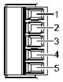
| Terminal no. | Signal name | Function |
|---|---|---|
| 1 | SD | Send data |
| 2 | RD | Receive data |
| 3 | SG | Signal ground |
| 4 | N.C. | - |
| 5 | N.C. | - |
Specifications of the LAN Port
| Item | Specifications | |
|---|---|---|
| Number of ports | 2 | |
| Communication interface | Ethernet 100BASE-TX / 10BASE-T | |
| Baud rate | 100 Mbps / 10 Mbps, automatic negotiation | |
| Max. segment length | 100 m (Note 1) | |
| Max. distance between nodes | 100BASE-TX 2 segments | |
| 10BASE-T 5 segments | ||
| Communication cable | Shielded twisted pair (TIA/EIA-568B CAT5e or higher) | |
| Communication protocol | TCP/IP UDP | |
| No. of simultaneous connections | LAN1 | Maximum 16 units (System connection: 1 unit, user connection: 15 units) |
| LAN2 | Max. 32 units, general-purpose: 16 units A cycle restriction is applied depending on the total number of connections. | |
| Communication method | Full-duplex / half-duplex communication | |
| TCP/IP protocol | TCP/IP compliant (IPV4) | |
| Functions | ・Modifying or holding the network settings (IP, Subnet, Gateway) ・Possible to set the different networks between Ethernet ports. ・Routing between Ethernet ports is not performed. | |
| LED display | LINK | Lit when connection is established with the device on the Ethernet network. |
| ACT | Flashes when some communication is performed such as transmitting commands and responses with the devices with established connections. | |
(Note 1)
The standards cite 100m as the maximum, but noise resistance measures such as attaching a ferrite core may be necessary in some cases, depending on the usage environment. Also, it is recommended to position a hub near the control board, and limit the length within 10m.
Specifications of the RTEX Port
| Item | Specifications |
|---|---|
| Baud rate | 100 Mbps |
| Physical layer | 100BASE-TX full duplex (IEEE 802.3u) |
| Cable | Shielded twisted pair (TIA/EIA-568B CAT5e or higher) |
| Topology | Ring |
| Insulation method | Pulse transformer |
| Connector | 8-pin RJ45 |
| Maximum cable length | Between nodes: 100 m, total length: 200 m |
| Communication cycle | 500 μs to 2 ms |
| Command update period | 500 μs to 4 ms |
| Operation command | Profile position, cyclic position / speed / torque |
| Number of connectable axes | 32 real axes , 20 virtual axes (Total 52 axes) |
Specifications of the EtherCAT Port
| Item | Specifications | |
|---|---|---|
| Baud rate | 100 Mbps | |
| Physical layer | 100BASE-TX full duplex (IEEE 802.3u) | |
| Cable | Shielded twisted pair (TIA/EIA-568B CAT5e or higher) | |
| Topology | Daisy chain (No branching) | |
| Insulation method | Pulse transformer | |
| Connector | 8-pin RJ45 | |
| Transmission distance | Between nodes: Max. 100 m | |
| Communication cycle | 500 μs more | |
| Operation command | Profile position, cyclic position / speed / torque | |
| Number of connectable axes | AGM1CSEC16T | 32 real axes , 20 virtual axes (Total 52 axes) |
| AGM1CSEC16P | 32 real axes , 20 virtual axes (Total 52 axes) | |
| AGM1CEEC008T | 12 real axes | |
| AGM1CEEC032T | 32 real axes | |
| AGM1CEEC064T | 64 real axes | |
| AGM1CEEC008P | 12 real axes | |
| AGM1CEEC032P | 32 real axes | |
| AGM1CEEC064P | 64 real axes | |
Performance Specifications
| Item | Specifications | |
|---|---|---|
| SD (SDHC) memory card | Support media | SD memory card, SDHC memory card Max. 32 GB |
| Supported format standard | Conforms to SD standard. | |
| Operating mode indicator | LED display (Flashes when accessed.) | |
| Detection when the cover is open | Available | |
| Memory capacity | Program | GM1 : 40 MB(Note 1) GM1P : 40 MB |
| Variable (non-hold) | GM1 : 40 MB(Note 1) GM1P : 40 MB | |
| Variable (hold) | 192 kB | |
| Clock / calender | Clock accuracy | 95 seconds max. per month (at 0 ℃) 15 seconds max. per month (at +25 ℃) 130 seconds max. per month (at +55 ℃) |
| Holding time maintained by the internal capacitor when a power failure occurs | 14 days or more (at +25℃) (Note 2) | |
(Note 1) 16 MB for firmware version Ver1.6.0.1 or earlier
(Note 2) The power-ON time of five minutes or longer is required.
High-speed Counter Input Specifications
| Item | Specifications | ||
|---|---|---|---|
| Input A, B, Z signals | |||
| 24 V DC / 12 V DC | 5 V DC | ||
| Open collector connection | Line driver connection | ||
| Insulation method | Optical coupler | ||
| Rated input voltage | 12 V DC to 24 V DC | 5 V DC | Equivalent to AM26LS31 |
| Operating voltage range | 10.8 V DC to 26.4 V DC | 3.5 V DC to 5.5 V DC | |
| Input points per common | Independent common for each point | ||
| Min. ON voltage / Min. ON current | 10 V DC / 4 mA | 3 V DC / 4 mA | |
| Max. OFF voltage / Max. OFF current | 2 V DC / 2 mA | 1 V DC / 0.5 mA | |
| Input impedance | Approx. 3.9 kΩ | Approx. 560 Ω | |
| Operating mode indicator | 6-point LED display | ||
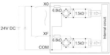
Input Specifications
| Item | Specifications | |
|---|---|---|
| Insulation method | Optical coupler | |
| Rated input voltage | 24 V DC | |
| Rated input current | Approx. 3 mA (at 24 V DC) | |
| Input impedance | Approx. 6.8 kΩ | |
| Operating voltage range | 21.6 to 26.4 V DC | |
| Min. ON voltage / Min. ON current | 19.2 V / 6 mA | |
| Max. OFF voltage / Max. OFF current | 2.4 V / 1 mA | |
| Response time | OFF→ON | 135 μs max. (Possible to change by using the input time constant selection function) |
| ON→OFF | 135 μs max. (Possible to change by using the input time constant selection function) | |
| Input points per common | 16 points/1 common | |
| Operating mode indicator | 16-point LED display (Lit when ON, SW selection) | |
| External connection method | Connector connection (Compliant with the MIL standard, 40P) | |
■Internal circuit diagram of the GM1 Controller input section
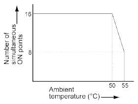
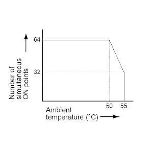
■Limitations on the number of simultaneous input ON points of the GM1 Controller
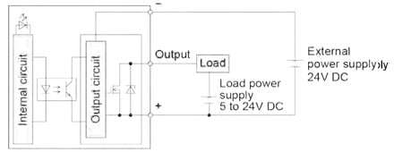
Output Specifications (Sink Type)
| Item | Specifications | |
|---|---|---|
| Insulation method | Optical coupler | |
| Output type | NPN Open collector | |
| Rated load voltage | 5 to 24 V DC | |
| Allowable load voltage range | 4.75 to 26.4 V DC | |
| Max. load current | 0.1 A | |
| Common restrictions | 1.6 A/common | |
| Max. inrush current | 1.0 A | |
| OFF state leakage current | 1 μA or less | |
| ON state max. voltage drop | 0.7 V or less | |
| Response time | OFF→ON | 2 μs or less (at an ambient temperature of 25 ℃) |
| ON→OFF | 5 μs or less (at an ambient temperature of 25 ℃) | |
| External power supply | Voltage | 4.75 to 26.4 V DC |
| Current | 15 mA or less (at 24V DC) | |
| Surge absorber | Zener diode | |
| Short-circuit protection | Provided (to automatically protect every eight points)(Note 1) | |
| Input points per common | 16 points/1 common | |
| Operating mode indicator | 16-point LED display (Lit when ON, SW selection) | |
| External connection method | Connector connection (Compliant with the MIL standard, 40P) | |
(Note 1)When the maximum inrush current is exceeded, eight output points in the same protection block are turned OFF simultaneously.
■Internal circuit diagram of the GM1 Controller Output section
■Limitations on the number of simultaneous output ON points of the GM1 Controller

Output specifications (source type) (EtherCAT-compatible GM1 Controller only)
| Item | Specifications | |
|---|---|---|
| Insulation method | Optical coupler | |
| Output type | PNP open collector | |
| Rated load voltage | 24 V DC | |
| Allowable load voltage range | 21.6 to 26.4 V DC | |
| Max. load current | 0.1 A | |
| Common restrictions | 1.6 A/common | |
| Max. inrush current | 1.0 A | |
| OFF state leakage current | 2 μA or less | |
| ON state max. voltage drop | 0.7 V or less | |
| Response time | OFF→ON | 2 μs or less (at an ambient temperature of 25 ℃) |
| ON→OFF | 5 μs or less (at an ambient temperature of 25 ℃) | |
| External power supply | Voltage | 21.6 to 26.4 V DC |
| Current | 200 mA or less (at 24V DC) | |
| Surge absorber | Zener diode | |
| Short-circuit protection | Provided (to automatically protect every eight points)(Note 1) | |
| Input points per common | 16 points/1 common | |
| Operating mode indicator | 16-point LED display (Lit when ON, SW selection) | |
| External connection method | Connector connection (Compliant with the MIL standard, 40P) | |
(Note 1) When the maximum inrush current is exceeded, eight output points in the same protection block are turned OFF simultaneously.
■Internal circuit diagram of the GM1 Controller Output section
■Limitations on the number of simultaneous output ON points of the GM1 Controller
Digital input unit
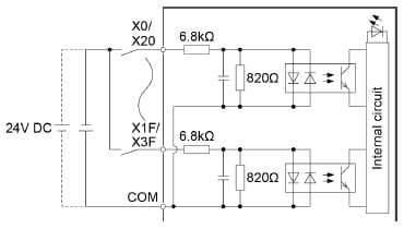
Input Specifications of the Digital input unit
| Item | Specifications | |
|---|---|---|
| Insulation method | Optical coupler | |
| Rated input voltage | 24 V DC | |
| Rated input current | Approx. 3.4 mA (at 24 V DC) | |
| Input impedance | Approx. 6.8 kΩ | |
| Operating voltage range | 20.4 to 26.4 V DC | |
| Min. ON voltage / Min. ON current | 19.2 V / 2.5 mA | |
| Max. OFF voltage / Max. OFF current | 5 V / 1.5 mA | |
| Response time | OFF→ON | 0.2 ms max. (Possible to change by using the input time constant selection function) |
| ON→OFF | 0.2 ms max. (Possible to change by using the input time constant selection function) | |
| Input points per common | 32 points/1 common | |
| Operating mode indicator | Operating mode indicator: 32-point LED display (Lit when ON, SW selection) | |
| External connection method | Connector connection (Compliant with the MIL standard, 40P, two pieces used) | |
■Internal circuit diagram of the Digital input unit
■Limitations on the number of simultaneous input ON points of the Digital input unit
Digital output unit
Output Specifications of the Digital Output Unit (Sink Type)
| Item | Specifications | |
|---|---|---|
| Insulation method | Optical coupler | |
| Output type | NPN Open collector | |
| Rated load voltage | 5 to 24 V DC | |
| Allowable load voltage range | 4.75 to 26.4 V DC | |
| Max. load current | 0.3 A (20.4 to 26.4 V DC), 30 mA (4.75 V DC) | |
| Common restrictions | 3.2 A/common | |
| Max. inrush current | 0.6 A | |
| OFF state leakage current | 1 μA or less | |
| ON state max. voltage drop | 0.5 V or less | |
| Response time | OFF→ON | 0.1 ms or less (Load current: 2 mA or more) |
| ON→OFF | 0.3 ms or less (Load current: 2 mA or more) | |
| External power supply | Voltage | 4.75 to 26.4 V DC |
| Current | 120 mA or less (at 24 V DC) | |
| Surge absorber | Zener diode | |
| Short-circuit protection | None | |
| Input points per common | 32 points/1 common | |
| Operating mode indicator | 32-point LED display (Lit when ON, selection using the display selector switch) | |
| External connection method | Connector connection (Compliant with the MIL standard, 40P, two pieces used) | |
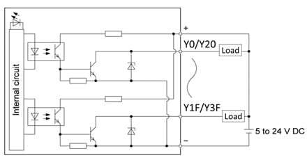
■Internal circuit diagram of the Digital output unit (sink type)
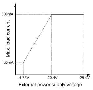
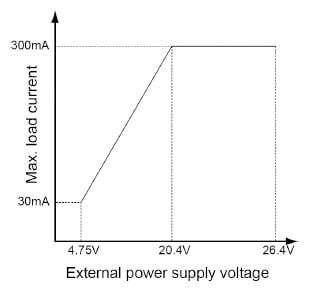
■Limitations on the load current of the Digital output unit (sink type)
The load current is limited as shown in the following figure depending on the voltage of the external power supply.
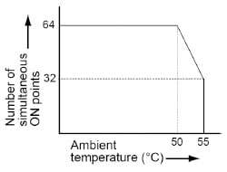
■Limitations on the number of simultaneous output ON points of the Digital output unit (sink type)

Output Specifications of the Digital Output Unit (Source Type)
| Item | Specifications | |
|---|---|---|
| Insulation method | Optical coupler | |
| Output type | PNP Open collector | |
| Rated load voltage | 5 to 24 V DC | |
| Allowable load voltage range | 4.75 to 26.4 V DC | |
| Max. load current | 0.3 A (20.4 to 26.4 V DC), 30 mA (4.75 V DC) | |
| Common restrictions | 3.2 A/common | |
| Max. inrush current | 0.6 A | |
| OFF state leakage current | 1 μA or less | |
| ON state max. voltage drop | 0.5 V or less | |
| Response time | OFF→ON | 0.1 ms or less (Load current: 2 mA or more) |
| ON→OFF | 0.5 ms or less (Load current: 2 mA or more) | |
| External power supply | Voltage | 4.75 to 26.4V DC |
| Current | 140 mA or less (at 24 V DC) | |
| Surge absorber | Zener diode | |
| Short-circuit protection | None | |
| Input points per common | 32 points/1 common | |
| Operating mode indicator | 32-point LED display (Lit when ON, selection using the display selector switch) | |
| External connection method | Connector connection (Compliant with the MIL standard, 40P, two pieces used) | |
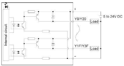
■Internal circuit diagram of the Digital output unit (source type)
■Limitations on the load current of the Digital output unit (source type)
The load current is limited as shown in the following figure depending on the voltage of the external power supply.
■Limitations on the number of simultaneous output ON points of the Digital output unit (source type)
Digital input / output unit
I/O Specifications of the Digital I/O Unit (Sink Type)
| Item | Specifications | ||
|---|---|---|---|
| Input specifications | Insulation method | Optical coupler | |
| Rated input voltage | 24 V DC | ||
| Rated input current | Approx. 3.4 mA (at 24 V DC) | ||
| Input impedance | Approx. 6.8 kΩ | ||
| Operating voltage range | 20.4 to 26.4 V DC | ||
| Min. ON voltage / Min. ON current | 19.2 V / 2.5 mA | ||
| Max. OFF voltage / Max. OFF current | 5 V / 1.5 mA | ||
| Response time | OFF→ON | 0.2 ms max. (Possible to change by using the input time constant selection function) | |
| ON→OFF | 0.2 ms max. (Possible to change by using the input time constant selection function) | ||
| Input points per common | 32 points/1 common | ||
| Output specifications | Insulation method | Optical coupler | |
| Output type | NPN Open collector | ||
| Rated load voltage | 5 to 24 V DC | ||
| Allowable load voltage range | 4.75 to 26.4 V DC | ||
| Max. load current | 0.3 A (20.4 to 26.4 V DC), 30 mA (4.75 V DC) | ||
| Common restrictions | 3.2 A/common | ||
| Max. inrush current | 0.6 A | ||
| OFF state leakage current | 1 μA or less | ||
| ON state max. voltage drop | 0.5 V or less | ||
| Response time | OFF→ON | 0.1 ms or less (Load current: 2 mA or more) | |
| ON→OFF | 0.3 ms or less (Load current: 2 mA or more) | ||
| External power supply | Voltage | 4.75 to 26.4 V DC | |
| Current | 120 mA or less (at 24 V DC) | ||
| Surge absorber | Zener diode | ||
| Short-circuit protection | None | ||
| Input points per common | 32 points/1 common | ||
| Operating mode indicator | 32-point LED display (Lit when ON, selection using the display selector switch) | ||
| External connection method | Connector connection (Compliant with the MIL standard, 40P, two pieces used) | ||
■Internal circuit diagram of the Digital input / output unit (sink type)
Input section (32 points)
Output section (32 points)
■Limitations on the load current of the Digital input / output unit (sink type)
The load current is limited as shown in the following figure depending on the voltage of the external power supply.
■Limitations on the number of simultaneous input ON points (max. number of points: 32) of the Digital input / output unit (sink type)
■Limitations on the number of simultaneous output ON points (max. number of points: 32) of the digital I/O unit (sink type)
I/O Specifications of the Digital I/O Unit (Source Type)
| Item | Specifications | ||
|---|---|---|---|
| Input specification | Insulation method | Optical coupler | |
| Rated input voltage | 24 V DC | ||
| Rated input current | Approx. 3.4 mA (at 24 V DC) | ||
| Input impedance | Approx. 6.8 kΩ | ||
| Operating voltage range | 20.4 to 26.4 V DC | ||
| Min. ON voltage / Min. ON current | 19.2 V / 2.5 mA | ||
| Max. OFF voltage / Max. OFF current | 5 V / 1.5 mA | ||
| Response time | OFF→ON | 0.2 ms max. (Possible to change by using the input time constant selection function) | |
| ON→OFF | 0.2 ms max. (Possible to change by using the input time constant selection function) | ||
| Input points per common | 32 points/1 common | ||
| Output specifications | Insulation method | Optical coupler | |
| Output type | PNP Open collector | ||
| Rated load voltage | 5 to 24 V DC | ||
| Allowable load voltage range | 4.75 to 26.4 V DC | ||
| Max. load current | 0.3 A (20.4 to 26.4 V DC), 30 mA (4.75 V DC) | ||
| Common restrictions | 3.2 A/common | ||
| Max. inrush current | 0.6 A | ||
| OFF state leakage current | 1 μA or less | ||
| ON state max. voltage drop | 0.5 V or less | ||
| Response time | OFF→ON | 0.1 ms or less (Load current: 2 mA or more) | |
| ON→OFF | 0.5 ms or less (Load current: 2 mA or more) | ||
| External power supply | Voltage | 4.75 to 26.4 V | |
| Current | 140 mA or less (at 24 V DC) | ||
| Surge absorber | Zener diode | ||
| Short-circuit protection | None | ||
| Input points per common | 32 points/1 common | ||
| Operating mode indicator | 32-point LED display (Lit when ON, selection using the display selector switch) | ||
| External connection method | Connector connection (Compliant with the MIL standard, 40P, two pieces used) | ||
■Internal circuit diagram of the Digital I/O unit (source type)
Input section (32 points)

Output section (32 points)

■Limitations on the load current of the Digital I/O unit (source type)
The load current is limited as shown in the following figure depending on the voltage of the external power supply.

■Limitations on the number of simultaneous input ON points (max. number of points: 32) of the Digital I/O unit (source type)

■Limitations on the number of simultaneous output ON points (max. number of points: 32) of the Digital I/O unit (source type)

Analog input unit
Input Specifications of the Analog Input Unit
| Item | Specifications | |
|---|---|---|
| No. of input points | 8 ch | |
| Input range (resolution) | Voltage | -10 to +10 V DC (Resolution: 1/64,000) 0 to +10 V DC (Resolution: 1/32,000) -5 to +5 V DC (Resolution: 1/64,000) 0 to +5 V DC (Resolution: 1/32,000) +1 to +5 V DC (Resolution: 1/25,600)(Note 1) |
| Current | 0 to +20 mA (Resolution: 1/32,000) +4 to +20 mA (Resolution: 1/25,600)(Note 1) | |
| Conversion speed | 50 μs/ch | |
| Exceeding the rated range | Possible to output up to the rated value ± 2 % With the 0 to 20 mA range, the lower limit is not supported for exceeding the rated range. (Note 2) | |
| Total accuracy | ±0.2 %F.S. or less (at +25 ℃) ±0.4 %F.S. or less (at 0 to +55 ℃) | |
| Input impedance | Voltage input: Approximately 1 MΩ; current input: Approximately 250 Ω | |
| Absolute max. input | Voltage input: -15 V to +15 V; current input: -30 mA to +30 mA | |
| Insulation method | Between input terminals and internal circuit: Photocoupler and isolated DC/DC converter Between channels: Non-insulated | |
| Execution / Non-execution channel settings | Possible to make non-converted channel settings. | |
| Input range selection | Possible to make settings on a channel-by-channel basis | |
| Average processing | Number of averaging times | Setting range of 2 to 60,000 times |
| Time average | Time setting range of 1 to 1,500 ms | |
| Moving average | Setting range of 2 to 2,000 times | |
| Offset / Gain settings | A desired value within the digital output range can be set for the offset value. Setting range: -3000 to +3000 A desired value within the digital output range can be set for the gain value. Setting range: +9,000 to +11,000 (90 % to 110 %) | |
| Scale conversion settings | A desired value within the digital output range can be set for the scale conversion setting value. Setting range: -32768 to +32767 | |
| Upper limit / lower limit comparison | Output if the value is outside the preset upper limit or lower limit. Setting range: -32768 to +32767 | |
| Max. / Min. hold | Holding max. / min. values sampled | |
| Disconnection detection | Disconnection detection is possible for the following ranges. Possible to select auto or manual resetting ・ 1 to 5 V range (Detection level: 0.7 V or less) ・ 4 to 20 mA range (Detection level: 2.8 mA or less.) | |
(Note 1) The full scale (F.S.) on the accuracy of an analog voltage input range from +1 to +5 V and that of an analog current input range from +4 to +20 mA are 0 to +5 V and 0 to +20 mA, respectively.
(Note 2) When a value exceeding the rated value ±2% is set, the output is rounded to a value equivalent to the rated value ±2%.
Analog output unit
Output Specifications of the Analog Output Unit
| Item | Specifications | |
|---|---|---|
| No. of output points | 4ch | |
| Output range (resolution) (Note 1) | Voltage | -10 to +10 V DC (Resolution: 1/64,000) 0 to +10 V DC (Resolution: 1/32,000) -5 to +5 V DC (Resolution: 1/64,000) 0 to +5 V DC (Resolution: 1/32,000) +1 to +5 V DC (Resolution: 1/25,600) |
| Current | 0 to +20 mA (Resolution: 1/32,000) +4 to +20 mA (Resolution: 1/25,600) | |
| Conversion speed | 50 μs/4 ch | |
| Exceeding the rated range | Possible to output up to the rated value ± 2 % With the 0 to 20 mA range, the lower limit is not supported for exceeding the rated range. (Note 2) | |
| Total accuracy | ±0.2 %F.S. or less (at +25 ℃) ±0.4 %F.S. or less (at 0 to +55 ℃) | |
| Output impedance (voltage output) | 0.5 Ω or less | |
| Maximum output current (voltage output) | 10 mA | |
| Output allowable load resistance (current output) | 500 Ω or less | |
| Insulation method | Between output terminals and internal circuit: Photocoupler and isolated DC/DC converter Between channels: Non-nsulated | |
| Conversion execution / nonexecution channel settings | Possible to make non-converted channel settings. | |
| Clipping function | Upper and lower output limits can be set for digital input values. Setting range: -32,640 to +32,640 | |
| Scale conversion settings | A desired value within the digital input range can be set for the scale conversion setting value. Setting range: -32768 to +32767 | |
| Offset / Gain settings | A desired value within the digital input range can be set for the offset value. Setting range: -3,000 to +3,000 A desired value within the digital input range can be set for the gain value. Setting range: +9,000 to +11,000 (90 % to 110 %) | |
| Analog output hold (in STOP mode) | A desired output value while in STOP mode can be set as a digital value. Setting range: -32640 to +32640 | |
(Note 1) The full scale (F.S.) on the accuracy of an analog voltage output range from +1 to +5 V and that of an analog current output range from +4 to +20 mA are 0 to +5 V and 0 to +20 mA, respectively.
(Note 2) When a value exceeding the rated value ±2% is set, the output is rounded to a value equivalent to the rated value ±2%.
Pulse output unit
Performance Specifications of the Pulse Output Unit
| Item | Specifications | ||
|---|---|---|---|
| Product No. | AGM1PG04T | AGM1PG04L | |
| Output type | Transistor | Line driver | |
| Number of axes controlled | 4 axis, independent | ||
| Position command | Command unit | Pulse unit (for increment or absolute) | |
| Max. pulse count | Signed 32 bits (-2,147,483,648 to +2,147,483,647 pulses) | ||
| Speed command | Command range | 1 pps to 500 kpps (can be set in 1 pps.) | 1 pps to 4 Mpps (can be set in 1 pps.) |
| Acceleration / deceleration command | Acceleration / deceleration method | Linear acceleration / deceleration, S-shaped acceleration / deceleration control | |
| S-shape pattern | Sine curve, Cubic curve (can be select) | ||
| Home return | Home return speed | Speed setting possible (changes return speed and search speed) | |
| Input signal | Home input, near home input, over limit input (+), over limit input (-) | ||
| Output signal | Deviation counter clear signal | ||
| Operation mode | ・ E-point control (Linear and S-shaped acceleration / deceleration) ・ P-point control (Linear and S-shaped acceleration / deceleration) ・ Home return (Home search) ・ JOG operation(Note 1) ・ JOG positioning ・ Pulser input operation(Note 2) Transfer multiplication ratio (x1, x2, x5, x10, x50, x100, x500, x1000) ・ Real-time frequency change function | ||
| Startup time | 0.001 ms / 0.005 ms / 0.02 ms | ||
| Output interface | Output mode | Pulse / Sign, CW / CCW | |
| Feedback counter function (Note 2) | Counting range | Signed 32 bits (-2,147,483,648 to +2,147,483,647 pulses) | |
| Input mode | 2-phase input, direction identification input, individual input (transfer multiple available for each mode) | ||
| Max. counting speed | 4 MHz (2-phase input) 1 MHz (Direction distinction input and individual input) | ||
| Other functions | ・ Built-in over limit input (+) and over limit input (-) ・ Servo ON output incorporated | ||
(Note 1) When Linear acceleration/deceleration operation is selected, the target speed can be changed during an operation.
(Note 2) "Pulser input operation" and "Feedback counter" use the same pulse input terminal. Either function of the two can only be used.
I/O specifications
- The Pulse Output Unit uses two connectors. The signal pins for two axes are assigned to one connector.
- AX1 and 2, and AX3 and 4 connectors have the completely same pin assignments.
Therefore, the same pin number functions the same. - Between the Transistor type and the Line driver type, the output terminal performance is different. However, the specifications of the input terminal and the power supply terminal are the same for both types.
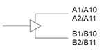
Transistor output type (AGM1PG04T)
| Pin No. | Signal name | Circuit | Specifications | ||
|---|---|---|---|---|---|
| Axis 1 / 3 | Axis 2 / 4 | ||||
| A1 | A10 | Pulse output A: 5 VDC output |
| Output | ・ Output type: Open collector ・ Operating voltage range: 4.75 to 26.4 V DC ・ Max. load current: 15 mA ・ ON state max. voltage drop: 0.6 V |
| B1 | B10 | Pulse output A: Open collector | |||
| A2 | A11 | Pulse output B: 5 VDC output | |||
| B2 | B11 | Pulse output B: Open collector | |||
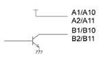
Line driver output type (AGM1PG04L)
| Pin No. | Signal name | Circuit | Specifications | ||
|---|---|---|---|---|---|
| Axis 1 / 3 | Axis 2 / 4 | ||||
| A1 | A10 | Pulse output A: Line driver (+) |
| Output | ・ Line driver output Equivalent to AM26C31 |
| B1 | B10 | Pulse output A: Line driver (-) | |||
| A2 | A11 | Pulse output B: Line driver (+) | |||
| B2 | B11 | Pulse output B: Line driver (-) | |||
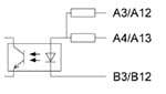
Common
| Pin No. | Signal name | Circuit | Specifications | ||
|---|---|---|---|---|---|
| Axis 1 / 3 | Axis 2 / 4 | ||||
| A3 | A12 | Home input: 24 VDC, SELV and LIM (+) |
| Input | ・ Operating voltage range: 21.6 to 26.4 V DC ・ Min. ON voltage / current: 19.2 V DC / 5.5 mA ・ Max. OFF voltage / current: 2.0 V DC / 2.0 mA ・ Input impedance: Approx. 3.9 kΩ ・ Pulse width: 100 μs or more |
| A4 | A13 | Home input: 5 VDC, SELV and LIM (+) | ・ Operating voltage range: 3.5 to 5.25 V DC (5 V DC, Line driver specifications) ・ Min. ON voltage / current: 3.0 V DC / 4 mA ・ Max. OFF voltage / current: 1.0 V DC / 0.5 mA ・ Input impedance: Approx. 560 Ω ・ Pulse width: 100 μs or more | ||
| B3 | B12 | Home input (-) | |||
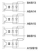
| B4 | B13 | COM [24V DC SELV and LIM (+)] |
| Input | ・ Operating voltage range: 21.6 to 26.4 V DC ・ Min. ON voltage / current: • Near home input (DOG) 19.2 V DC / 5.0 mA • Limit input (+) Limit input (-) Positioning control start input (Timing input) 19.2 V DC / 2.6 mA ・ Max. OFF voltage / current: 2.0 V DC / 1.5 mA ・ Input impedance: • Near home input (DOG) Approx. 3.6 kΩ • Limit input (+) Limit input (-) Positioning control start input (Timing input) Approx. 6.8 kΩ ・ Pulse width: 500 μs or more |
| A5 | A14 | Near home input (DOG) | |||
| A6 | A15 | Limit input (+) | |||
| B6 | B15 | Limit input (-) | |||
| A19 | B19 | Timing input | |||
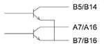
| B5 | B14 | Servo ON output (+) |
| Output | ・ Output type: Open collector ・ Operating voltage range: 4.75 to 26.4 V DC ・ Max. load current: 10 mA ・ ON state max. voltage drop: 1.0 V |
| A7 | A16 | Deviation counter clear (+) | |||
| B7 | B16 | COM | |||
| A8 | A17 | Pulse input A (+) |
| Input | ・ Operating voltage range: 3.5 to 5.25 V DC (5 V DC, Line driver specifications) ・ Min. ON voltage / current: 3.0 V DC / 3.2 mA ・ Max. OFF voltage / current: 1.0 V DC / 0.5 mA ・ Input impedance: Approx. 560 Ω ・ Pulse width: 0.5 μs or more (Each phase Max. 1 MHz) |
| B8 | B17 | Pulse input A (-) | |||
| A9 | A18 | Pulse input B (+) | |||
| B9 | B18 | Pulse input B (-) | |||
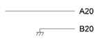
| A20 | External power supply input: 24 VDC, SELV and LIM (+) |
| Power supply | ・ Supplied power range: 21.4 to 26.4 V DC ・ Consumption current: 90 mA or less | |
| B20 | External power supply input: 24 VDC, SELV and LIM (-) | ||||

Serial Communication Unit
Serial Communication Unit Communication Specifications
| Item | Specifications | |||
|---|---|---|---|---|
| Product No. | AGM1NSCS2 | AGM1NSCM2 | AGM1NSCS1M1 | |
| Interface | Connector1 | RS-232C | RS-422A / 485 | RS-232C |
| Connector2 | RS-232C | RS-422A / 485 | RS-422A / 485 | |
| Communication method | RS-232C | Full-duplex / half-duplex | - | Full-duplex / half-duplex |
| RS-422A | - | Full-duplex / half-duplex | Full-duplex / half-duplex | |
| RS-485 | - | Half-duplex | Half-duplex | |
| Transmission distance (Note 1) | RS-232C | Max. 15 m | - | Max. 15 m |
| RS-422A | - | Max. 1,200 m (Note 1) (total extension distance) | Max. 1,200 m (Note 1) (total extension distance) | |
| RS-485 | ||||
| Transmission mode Number of destination units | RS-232C | 1:1 | - | 1:1 |
| RS-422A | - | 1:1 | 1:1 | |
| RS-485 | - | 1:N (N = 32 max.) | 1:N (N = 32 max.) | |
| Protocol | General-purpose communication / Modbus-RTU (master / slave) | |||
| Baud rate | General-purpose communication | 1,200 / 2,400 / 4,800 / 9,600 / 19,200 / 38,400 / 57,600 / 115,200 / 230,400 bps | ||
| Modbus-RTU | 1,200 / 2,400 / 4,800 / 9,600 / 19,200 / 38,400 / 57,600 / 115,200 bps | |||
| Maximum data length | General-purpose communication | 1,024 Byte | ||
| Modbus-RTU | 252 Byte | |||
| Communication format | Data length | 7 bit / 8 bit | ||
| Parity | None, odd, even | |||
| Stop code | 1bit / 2bit | |||
| Start code | None | |||
| End code | None | |||
(Note 1): Check the transmission distance using the actual unit as it may depend on the destination device. The recommended transmission distance is 100 m or less.
■ RS-232C port
● Circuit diagram

● Terminal layout diagram

| Pin No. | Signal name | Specifications |
|---|---|---|
| 1 | SD | Send data |
| 2 | RD | Receive data |
| 3 | RS | Request to send |
| 4 | CS | Clear to send |
| 5 | N.C. | - |
| 6 | N.C. | - |
| 7 | N.C. | - |
| 8 | SG | Signal ground |
■ RS-422A/485 port
● Circuit diagram


● Terminal layout diagram

| Pin No. | Signal name | Specifications | |
|---|---|---|---|
| RS-422A | RS-485 | ||
| 1 | TERMA | Termination resistor connection terminal (Note 1) | Termination resistor connection terminal (Note 1) |
| 2 | TERMB | Termination resistor connection terminal (Note 1) | Termination resistor connection terminal (Note 1) |
| 3 | N.C. | - | - |
| 4 | RD+/SR+ | Receive data (+) | Send and receive data (+) |
| 5 | RD-/SR- | Receive data (-) | Send and receive data (-) |
| 6 | SD+ | Send data (+) | - |
| 7 | SD- | Send data (-) | - |
| 8 | SG | Signal ground | Signal ground |
(Note 1): When the TERMA and TERMB terminals are short-circuited, the termination resistor (120 Ω) is connected in the internal circuit.
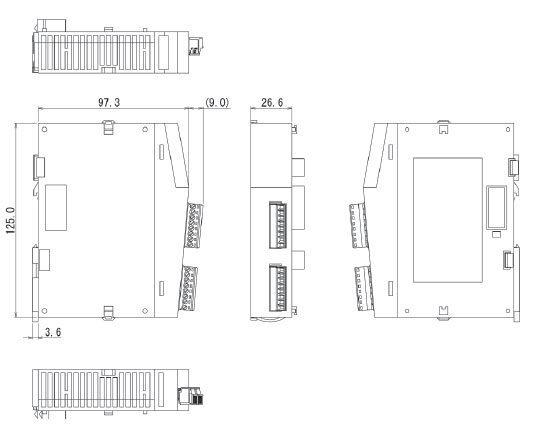
Dimensions
- Unit: mm in
GM1 controller
RTEX type
AGM1CSRX16T
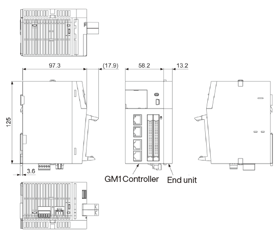
Weight: Approx. 370 g (including the terminal block and end cover)
GM1/GM1P controller
EtherCAT type
AGM1CSEC16T
AGM1CSEC16P
AGM1CEEC008T
AGM1CEEC032T
AGM1CEEC064T
AGM1CEEC008P
AGM1CEEC032P
AGM1CEEC064P
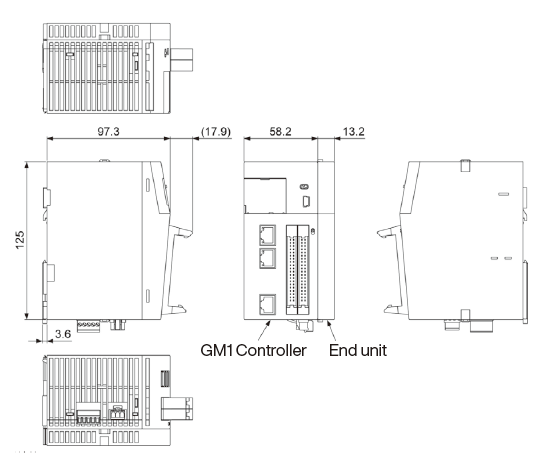
Weight: Approx. 370 g (including the terminal block and end cover)
Digital Input / output unit / Pulse output unit
AGM1X64D2
AGM1Y64T
AGM1Y64P
AGM1XY64D2T
AGM1XY64D2P
AGM1PG04T
AGM1PG04L
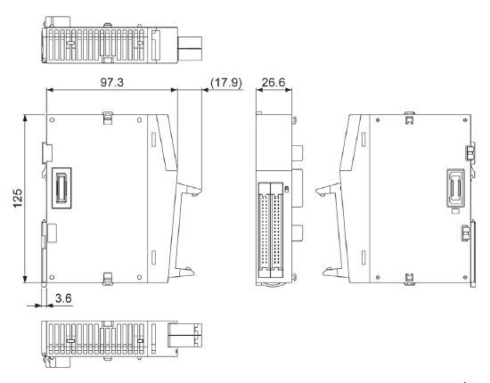
Weight: Approx. 160 g (including the terminal block)
Analog input / output unit
AGM1AD8
AGM1DA4
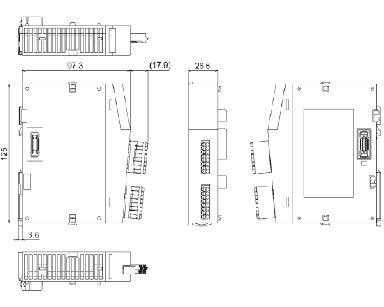
Weight: Approx. 150 g (including the terminal block)
Serial Communication Unit
AGM1NSCS2
AGM1NSCM2
AGM1NSCS1M1
Weight: Approx. 150 g (including the terminal block)