停產資訊
Lineup
Motor Lineup
Low inertia
| Motor | Voltage | Rated output (kW) | Rated rotational speed (Max. speed) (r/min) | Rotary encoder | Enclosure (*1) | Features | |
|---|---|---|---|---|---|---|---|
| 20-bit incremental | 17-bit/ absolute | ||||||
MSMJ | 200 V | 0.2 0.4 | 3000 | ○ | ○ | IP65 | - |
| 0.75 | 3000 (4500) | ||||||
| MSMD | 100 V | 0.05 0.1 | 3000 | ○ | ○ | IP65 | • Leadwire type • Small capacity • Suitable for high speed application • Suitable for all applications |
| 200 V | 0.75 | 3000 | |||||
MSME | 100 V 200 V | 0.05 0.1 0.2 0.4 | 3000 (6000) | ○ | ○ | IP67 | • Small capacity • Suitable for high speed application • Suitable for all applications |
| 200 V | 0.75 | ||||||
MSME | 400 V | 0.75 | 3000 | ○ | ○ | IP65(*2) | • Middle capacity • Suitable for the machines directly coupled with ball screw and high stiffness and high repetitive application |
| 200 V 400 V | 1.0 1.5 2.0 3.0 | ||||||
| 4.0 5.0 | 3000 (4500) | ||||||
Middle inertia
| Motor | Voltage | Rated output (kW) | Rated rotational speed (Max. speed) (r/min) | Rotary encoder | Enclosure (*1) | Features | |
|---|---|---|---|---|---|---|---|
| 20-bit incremental | 17-bit/ absolute | ||||||
MDME | 400 V | 0.4 0.6 | 2000 | ○ | ○ | IP65(*2) | • Middle capacity • Suitable for low stiffness machines with belt driven |
| 200 V 400 V | 1.0 1.5 2.0 3.0 4.0 5.0 | ||||||
| 7.5(*3) | 1500 (3000) | ||||||
| 11.0(*3) 15.0(*3) | 1500 (2000) | ||||||
| MFME (Flat type) (*3)  | 200 V 400 V | 1.5 2.5 4.5 | 2000 (3000) | ○ | ○ | IP67 | • Middle capacity • Flat type and suitable for machines with space limitation |
| MGME (Low speed/ High torque type)  | 200 V 400 V | 0.9 2.0 3.0 4.5(*3) 6.0(*3) | 1000 (2000) | ○ | ○ | IP65(*2) | • Middle capacity • Suitable for low speed and high torque application |
High inertia
| Motor | Voltage | Rated output (kW) | Rated rotational speed (Max. speed) (r/min) | Rotary encoder | Enclosure (*1) | Features | |
|---|---|---|---|---|---|---|---|
| 20-bit incremental | 17-bit/ absolute | ||||||
MHMD | 100 V 200 V | 0.2 | 3000 | ○ | ○ | IP65 | • Leadwire type • Small capacity • Suitable for low stiffness machines with belt driven |
| 200 V | 0.75 | 3000 (4500) | |||||
MHME | 200 V 400 V | 1.0 1.5 | 2000 | ○ | ○ | IP65(*2) | • Middle capacity • Suitable for low stiffness machines with belt driven,and large load moment of inertia |
| 7.5(*3) | 1500 (3000) | ||||||
(*1)Except for output shaft, and connector.
(*2)IP67 motor is also available.
(*3)Only IP67 motor is avilable.
Driver Lineup
| Series | Control method | Interface/ Communication function | Safety Function |
|---|---|---|---|
A5 Series | Position control, Velocity control, Torque control, | Analog/Pulse input, Modbus (RS485 /RS232) | with |
| A5Ⅱ Series | Position control, Velocity control, Torque control, | Analog/Pulse input, Modbus (RS485 /RS232) | with |
A5E Series | Position control | Pulse input | without |
| A5ⅡE Series | Position control, 2DOF settings | Pulse input | without |
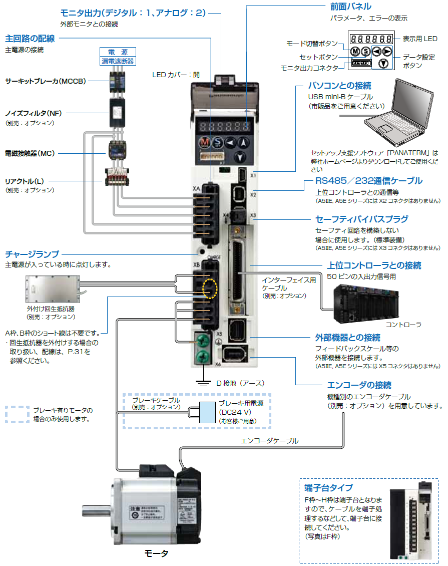
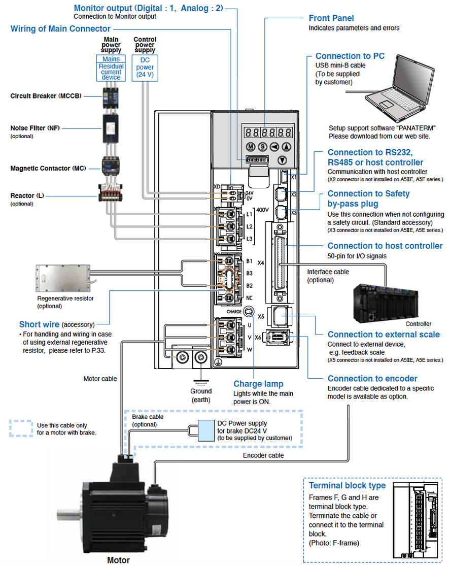
System Configuration
Overall Wiring
[Connector type (100/200 V: A-frame to E-frame)]
Caution
Apply adequate tightening torque to the product mounting screw by taking into consideration strength of the screw and the characteristics of material to which the product is installed. Overtightening can damage the screw and/or material; undertightening can result in loosening.
Example) Steel screw (M5) into steel section: 2.7 N·m to 3.3 N·m.
[Connector type (400 V: D, E-frame)]
Note
Initial setup of rotational direction: positive = CCW and negative = CW. Pay an extra attention.
Driver and List of Applicable Peripheral Equipments
| Driver | Applicable motor | Voltage *1 | Rated output | Required Power (at the rated load) | Circuit breaker (rated current) | Noise filter (Single phase/ 3-phase) | Surge absorber (Single phase/3-phase) | Noise filter for signal | Rated operating current of magnetic (contactor Contact configuration)*2 | Diameter and withstand voltage of main circuit cable | Crimp terminal for main circuit terminal block *4 | Diameter and withstand voltage of control power supply cable | Crimp terminal for control power supply terminal block | Diameter and withstand voltage of motor cable *5 | Diameter and withstand voltage of brake cable |
|---|---|---|---|---|---|---|---|---|---|---|---|---|---|---|---|
| MADH MADK | MSMD MSME MHMD | Single phase, 100 V | 50 W to 100 W | approx. 0.4 kVA | 10 A | DV0P4170 | DV0P4190 | DV0P1460 | 20 A (3P+1a) | 0.75 mm2/ AWG18 600 VAC or more | Connection to exclusive connector | 0.75 mm2/ AWG18 600 VAC or more | Connection to exclusive connector | 0.75 mm2/ AWG18 600 VAC or more | 0.28 mm2 to 0.75 mm2/ AWG22 to AWG18 100 VAC or more |
| Single/ 3-phase, 200 V | 50 W to 200 W | approx. 0.5 kVA | DV0P4170/ DV0PM20042 | DV0P4190/ DV0P1450 | |||||||||||
| MBDH MBDK | MSMD MSME MHMD | Single 100 V | 200 W | approx. 0.5 kVA | DV0P4170 | DV0P4190 | |||||||||
| Single/ 3-phase, 200 V | 400 W | approx. 0.9 kVA | DV0P4170/ DV0PM20042 | DV0P4190/ DV0P1450 | |||||||||||
| MCDH MCDK | MSMD MSME MHMD | Single 100 V | 400 W | approx. 0.9 kVA | DV0PM20042 | DV0P4190 | |||||||||
| Single/ 3-phase, 200 V | 750 W | approx. 1.3 kVA | 15 A | DV0P4190/ DV0P1450 | |||||||||||
| MDDH MDDK | MDME | Single/ 3-phase, 200 V | 1.0 kW | approx. 1.8 kVA | DV0P4220 | 30 A (3P+1a) | 2.0 mm2/ AWG14 600 VAC or more | 2.0 mm2/ AWG14 600 VAC or more | 0.75 mm2/ AWG18 100 VAC or more | ||||||
| MHME | |||||||||||||||
| MGME | 0.9 kW | approx. 1.8 kVA | 20 A | ||||||||||||
| MSME | 1.0 kW | approx. 1.8 kVA | |||||||||||||
| MHME | 1.5 kW | approx. 2.3 kVA | |||||||||||||
| MDME | |||||||||||||||
| MFME | |||||||||||||||
| MSME | |||||||||||||||
| MDME | 3-phase, 400 V | 400 W | approx. 0.9 kVA | 10 A | FN258L-16-07 (Recommended component ) | DV0PM20050 | 20 A (3P+1a) | 0.52 mm2/ AWG20 100 VAC or more | |||||||
| MDME | 600 W | approx. 1.2 kVA | |||||||||||||
| MSME | 750 W | approx. 1.6 kVA | |||||||||||||
| MSME | 1.0 kW | approx. 1.8 kVA | |||||||||||||
| MDME | |||||||||||||||
| MHME | |||||||||||||||
| MGME | 0.9 kW | ||||||||||||||
| MSME | 1.5 kW | approx. 2.3 kVA | |||||||||||||
| MDME | |||||||||||||||
| MFME | |||||||||||||||
| MHME | |||||||||||||||
| MEDH MEDK | MDME | 3-phase, 200 V | 2.0 kW | approx. 3.3 kVA | 30 A | DV0PM20043 | DV0P1450 | DV0P1460 RJ8035 (Recommended component ) *6 | 60 A (3P+1a) | 0.75 mm2/ AWG18 600 VAC or more | |||||
| MSME | |||||||||||||||
| MHME | |||||||||||||||
| MFME | 2.5 kW | approx. 3.8 kVA | |||||||||||||
| MSME | 3-phase, 400 V | 2.0 kW | approx. 3.3 kVA | 15 A | FN258L-16-07 (Recommended component ) | DV0PM20050 | DV0P1460 | 30 A (3P+1a) | 0.52 mm2/ AWG20 100 VAC or more | ||||||
| MDME | |||||||||||||||
| MHME | |||||||||||||||
| MFME | 2.5 kW | approx. 3.8 kVA | |||||||||||||
| MFDH MFDK | MGME | 3-phase, 200 V | 2.0 kW | approx. 3.8 kVA | 50 A | DV0P3410 | DV0P1450 | DV0P1460 RJ8035 (Recommended component ) *6 | 60 A (3P+1a) | 3.5 mm2/ AWG12 600 VAC or more |
Terminal block M5 | 0.75 mm2/ AWG18 600 VAC or more |
Terminal block M5 | 3.5 mm2/ AWG12 600 VAC or more | |
| MDME | 3.0 kW | approx. 4.5 kVA | |||||||||||||
| MHME | |||||||||||||||
| MSME | |||||||||||||||
| MGME | |||||||||||||||
| MDME | 4.0 kW | approx. 6.0 kVA | 100 A (3P+1a) | ||||||||||||
| MHME | |||||||||||||||
| MSME | |||||||||||||||
| MFME | 4.5 kW | approx. 6.8 kVA | |||||||||||||
| MGME | approx. 7.5 kVA | ||||||||||||||
| MDME | 5.0 kW | ||||||||||||||
| MHME | |||||||||||||||
| MSME | |||||||||||||||
| MGME | 3-phase, 400 V | 2.0 kW | approx. 3.8 kVA | 30 A | FN258L-30-07 (Recommended component ) | DV0PM20050 | DV0P1460 | 60 A (3P+1a) |
Terminal block M4 | 0.75 mm2/ AWG18 100 VAC or more |
Terminal block M3 | ||||
| MSME | 3.0 kW | approx. 4.5 kVA | |||||||||||||
| MDME | |||||||||||||||
| MGME | |||||||||||||||
| MHME | |||||||||||||||
| MSME | 4.0 kW | approx. 6.0 kVA | |||||||||||||
| MDME | |||||||||||||||
| MHME | |||||||||||||||
| MFME | 4.5 kW | approx. 6.8 kVA | |||||||||||||
| MGME | approx. 7.5 kVA | ||||||||||||||
| MSME | 5.0 kW | ||||||||||||||
| MDME | |||||||||||||||
| MHME | |||||||||||||||
| MGDH MGDK | MDME | 3-phase, 200 V | 7.5 kW | approx. 11 kVA | 60 A | FS5559-60-34 (Recommended component ) | DV0P1450 | DV0P1460 RJ8095 Recommended ( component ) T400-61D (Recommended component ) *6 | 100 A (3P+1a) | 5.3 mm2/ AWG10 600 VAC or more |
Terminal block M5 | 0.75 mm2/ AWG18 600 VAC or more |
Terminal block M5 | 13.3 mm2/ AWG6 600 VAC or more | |
| MGME | 6.0 kW | approx. 9.0 kVA | |||||||||||||
| MHME | 7.5 kW | approx. 11 kVA | |||||||||||||
| MDME | 3-phase, 400 V | 7.5 kW | approx. 11 kVA | 30 A | FN258-42-07 or FN258-42-33 (Recommended component ) | DV0PM20050 | 60 A (3P+1a) | 0.75 mm2/ AWG18 100 VAC or more | |||||||
| MGME | 6.0 kW | approx. 9.0 kVA | |||||||||||||
| MHME | 7.5 kW | approx. 11 kVA | |||||||||||||
| MHDH MHDK | MDME | 3-phase, 200 V | 11 kW | approx. 17 kVA | 100 A | FS5559-80-34 (Recommended component ) | DV0P1450 | 150 A (3P+1a) | 13.3 mm2/ AWG6 600 VAC or more *3 |
Terminal block M6 | 0.75 mm2/ AWG18 600 VAC or more |
Terminal block M4 | |||
| 15 kW | approx. 22 kVA | 125 A | 21.1 mm2/ AWG4 600 VAC or more | ||||||||||||
| 3-phase, 400 V | 11 kW | approx. 17 kVA | 50 A | FN258-42-07 or FN258-42-33 (Recommended component ) | DV0PM20050 | 100 A (3P+1a) | 0.75 mm2/ AWG18 100 VAC or more | 13.3 mm2/ AWG6 600 VAC or more | |||||||
| 15 kW | approx. 22 kVA | 60 A | 21.1 mm2/ AWG4 600 VAC or more |


*1 Select peripheral equipments for single/3phase common specification according to the power source.
*2 For the external dynamic brake resistor, use the magnetic contactor with the same rating as that for the main circuit.
*3 When use the external regenerative resistor of the option (DV0PM20058, DV0PM20059), use the cable with the same diameter as the main circuit cable.
*4 For the ground screw, use the same crimp terminal as that for the main circuit terminal block.
*5 The diameter of the ground cable and the external dynamic brake resistor cable must be equal to, or larger than that of the motor cable.
The motor cable is a shield cable, which conforms to the EC Directives and UL Standards. (G, H-frame only)
*6 Use thses products to suit an international standard.
●About circuit breaker and magnetic contactor
To comply to EC Directives, install a circuit breaker between the power and the noise filter without fail, and the circuit breaker should conform to IEC Standards and UL recognized (Listed and ![]() marked).
marked).
Suitable for use on a circuit capable of delivering not more than 5000 Arms symmetrical amperes, below the maximum input voltage of the product.
If the short-circuit current of the power supply exceeds this value, install a current limit device (current limiting fuse, current limiting circuit breaker, transformer, etc.) to limit the short-circuit current.
<Remarks>
- Select a circuit breaker and noise filter which match to the capacity of power supply (including a load condition).
● Terminal block and protective earth terminals
- Use a copper conductor cables with temperature rating of 75 ℃ or higher.
- Use the attached exclusive connector for A-frame to E-frame, and maintain the peeled off length of 8 mm to 9 mm.
■Fastening torque list (Terminal block screw/Terminal cover fastening screw)
| Driver | Terminal block screw | Terminal cover fastening screw | |||
|---|---|---|---|---|---|
| Frame | Terminal name | Nominal size | Fastening torque (N・m) | Nominal size | Fastening torque (N・m) |
| F(200 V) | L1, L2, L3, L1C, L2C, B1, B2, B3, NC, U, V, W | M5 | 1.0 to 1.7 | M3 | 0.19 to 0.21 |
| F(400 V) | 24V、0V | M3 | 0.4 to 0.6 | ||
| L1, L2, L3, B1, B2, B3, NC, U, V, W | M4 | 0.7 to 1.0 | |||
| G | L1C, L2C, 24 V, 0 V, DB1, DB2, DB3, DB4, NC | M5 | 1.0 to 1.7 | ||
| L1, L2, L3, B1, B2, NC, U, V, W | M5 | 2.0 to 2.4 | M3 | 0.3 to 0.5 | |
| H | L1C, L2C, 24 V, 0 V, DB1, DB2 | M4 | 0.7 to 1.0 | M5 | 2.0 to 2.5 |
| L1, L2, L3, B1, B2, NC, U, V, W | M6 | 2.2 to 2.5 | |||
■Fastening torque list (Ground terminal screw/Connector to host controller [X4])
| Driver frame | Ground screw | Connector to host controller (X4) | ||
|---|---|---|---|---|
| Nominal size | Fastening torque (N・m) | Nominal size | Fastening torque (N・m) | |
| A to E | M4 | 0.7 to 0.8 | M2.6 | 0.2±0.05 |
| G | M5 | 1.4 to 1.6 | ||
| H | M6 | 2.4 to 2.6 | ||
[Caution]
- Applying fastening torque larger than the maximum value may result in damage to the product.
- Do not turn on power without tightening all terminal block screws properly, otherwise, loose contacts may generate heat (smoking, firing).
[Remarks]
- To check for looseness, conduct periodic inspection of fastening torque once a year.
Dimensions
Dimensions of Motor
For Motors, please refer to each part number detail.
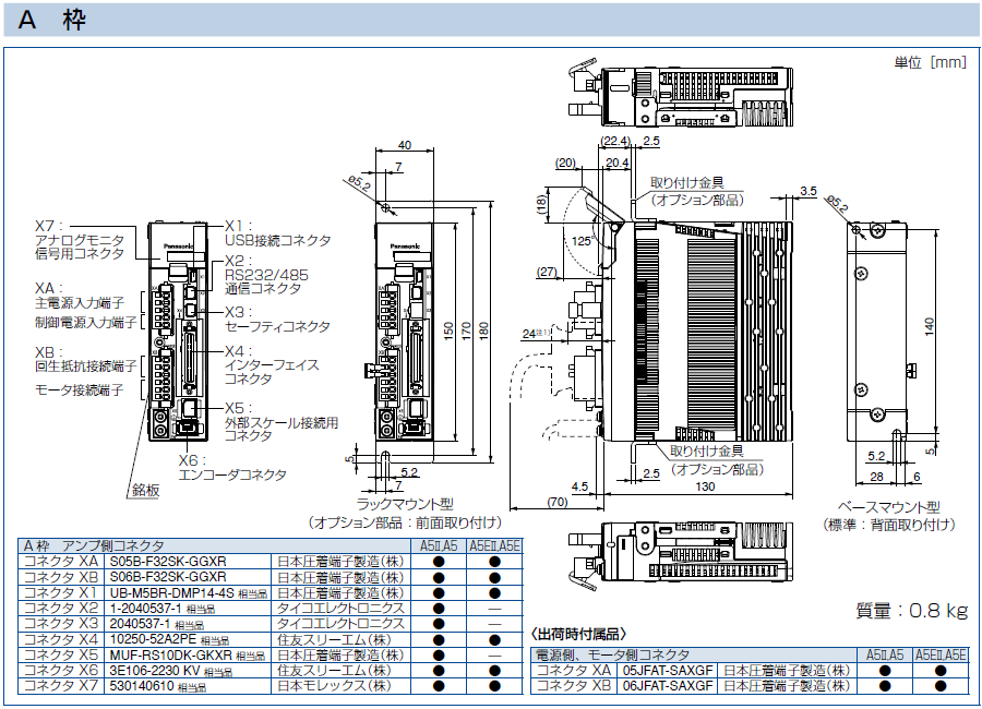
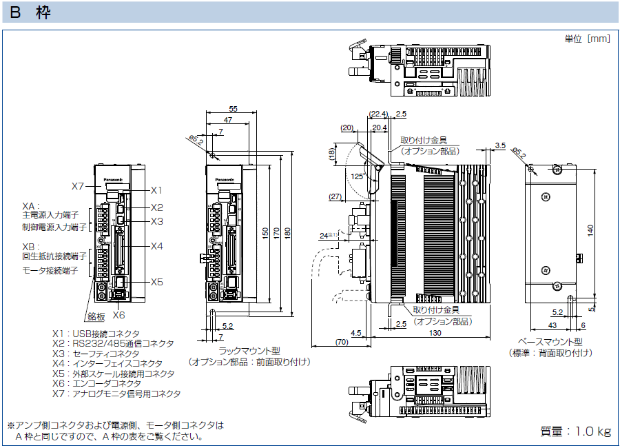
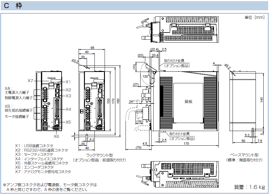
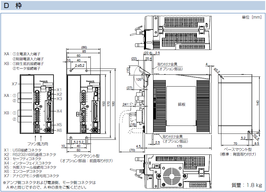
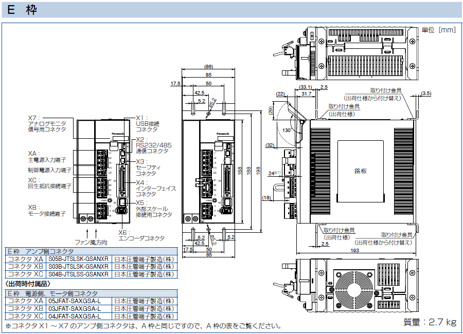
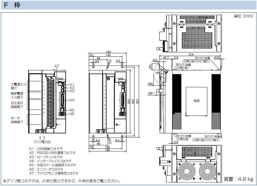
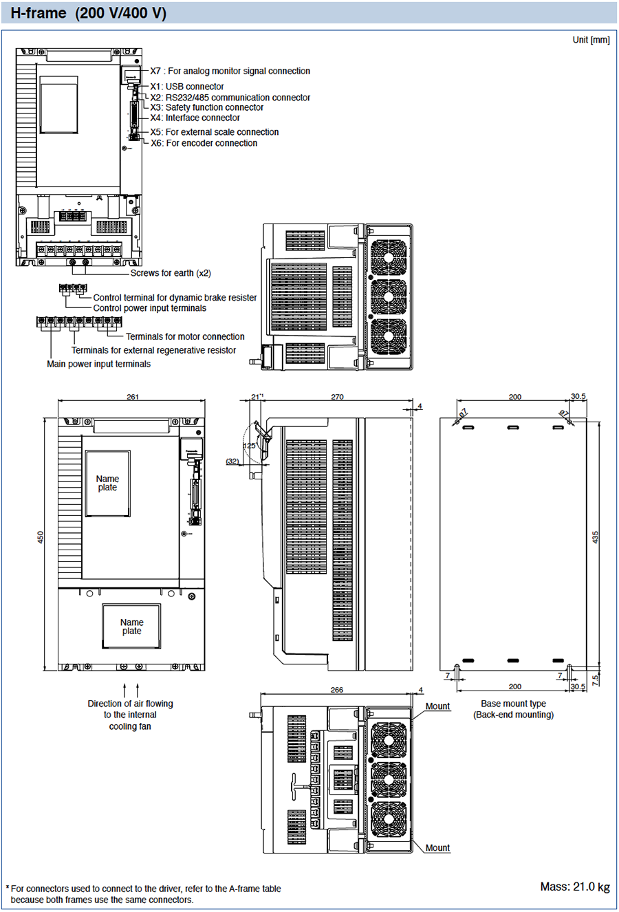
Dimensions of Driver
● The size of A5Ⅱ, A5 series and A5ⅡE, A5E series is same.
*1 The height of the safety by-pass provided plug is one of the 14 mm or 24 mm to connector X3.
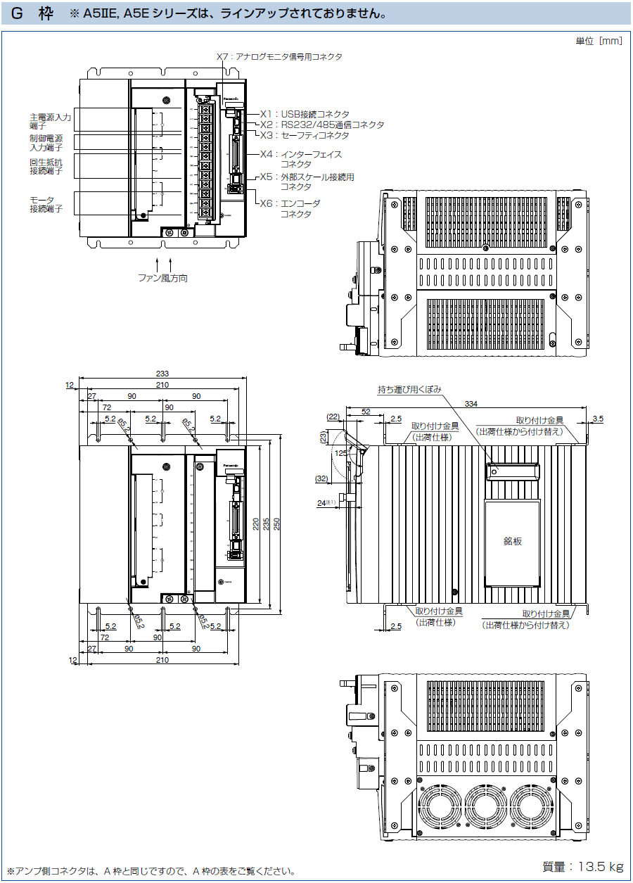
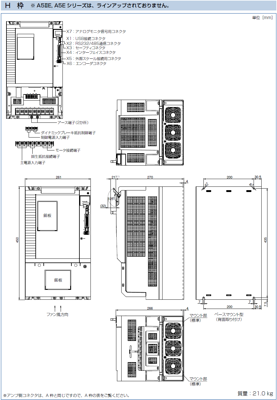
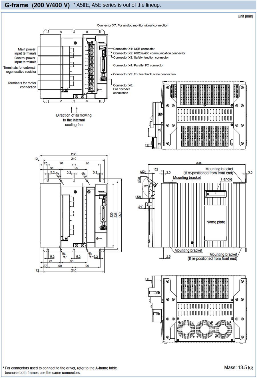
●A5ⅡE, A5E series is out of the lineup.
*1 The height of the safety by-pass provided plug is one of the 11 mm or 21 mm to connector X3.
- 1.Wiring Diagram (Wiring to Connector, XA, XB, XC, XD and Terminal Block)
- 2.Safety Function (Wiring to the Connector, X3)
- 3.Control Circuit Diagram (Wiring to the Connector, X4, X5, X6)
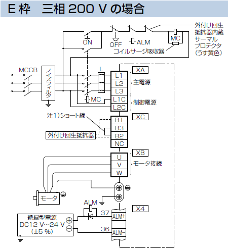
1.Wiring Diagram
Wiring to Connector, XA, XB, XC, XD and Terminal Block

Note.1)
| Frame No. | Short wire (Accessory) | Built-in regenerative resistor | Connection of the connector XB | |
|---|---|---|---|---|
| In case of using an external regenerative resistor. | In case of not using an external regenerative resistor. | |||
| A-frame B-frame | without | without | ・Always open between B2-B3 ・Connect an external regenerative resistor between B1-B2 | ・Always open between B2-B3 |
| C-frame D-frame | with | with | ・Remove the short wire accessory from between B2-B3. ・Connect an external regenerative resistor between B1-B2 | ・Shorted between B2-B3 with an attached short wire |
Note.1)
| Frame No. | Short wire (Accessory) | Built-in regenerative resistor | Connection of the connector XC | |
|---|---|---|---|---|
| In case of using an external regenerative resistor. | In case of not using an external regenerative resistor. | |||
| E-frame | with | with | ・Remove the short wire accessory from between B2-B3. ・Connect an external regenerative resistor between B1-B2 | ・Shorted between B2-B3 with an attached short wire |
Note.1)
| Frame No. | Short bar (Accessory) | Built-in regenerative resistor | Connection of terminal block | |
|---|---|---|---|---|
| In case of using an external regenerative resistor. | In case of not using an external regenerative resistor. | |||
| F-frame | with | with | • Remove the short bar accessory from between B2-B3. • Connect an external regenerative resistor between B1-B2 | • Shorted between B2-B3 with an attached short bar |
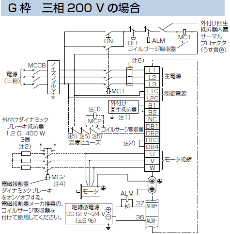
Note.1) About regenerative resistor
| Frame No. | Short bar (Accessory) | Built-in regenerative resistor | Connection of terminal block | |
|---|---|---|---|---|
| In case of using an external regenerative resistor. | In case of not using an external regenerative resistor. | |||
| G-frame | without | without | • Connect an external regenerative resistor between B1-B2 | • Open between B1-B2 |
Note.2) About dynamic brake resistor
| Frame No. | Short bar (Accessory) | Built-in dynamic brake resistor | Connection of terminal block | |
|---|---|---|---|---|
| In case of using an external dynamic brake resistor. | In case of not using an external dynamic brake resistor. | |||
| G-frame | with | with | • Remove attached short bar between DB3-DB4. • Connect external dynamic brake resistor as shown above. | • Shorted with attached short bar between DB3-DB4 • Open between DB1-DB2 |
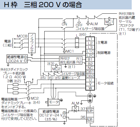
Note.1) About regenerative resistor
| Frame No. | Short bar (Accessory) | Built-in regenerative resistor | Connection of terminal block | |
|---|---|---|---|---|
| In case of using an external regenerative resistor. | In case of not using an external regenerative resistor. | |||
| H-frame | without | without | (External regenerative resistor terminal) • Terminal R1, R2 connect to B1, B2 • Terminal T1, T2 connection as shown above • Terminal 24 V, 0 V connect to DC power supply of DC24 V. • E terminal connect to the ground | • Open between B1-B2 |
Specification of external regenerative resistor, please refer to “Options Components”.
Note.2) About dynamic brake resistor
| Frame No. | Short bar (Accessory) | Built-in dynamic brake resistor | Connection of terminal block | |
|---|---|---|---|---|
| In case of using an external dynamic brake resistor. | In case of not using an external dynamic brake resistor. | |||
| H-frame | without | without | • Connect external dynamic brake resistor as shown above. | • Open between DB1-DB2 |
<common for G & H frame>
Note.3) Magnetic contactor MC2 must be the same rating as the contactor MC1 in the main circuit.
Note.4) Servo may be turned on in the external sequence if the contact deposits: to protect the system, provide the auxiliary contact.
Note.5) Provide an external protective device (e.g. thermal fuse) to monitor the temperature of the external dynamic brake resistor.
Note.6) Reactor should be prepared by the customer.
Note.1) Shielding the circuit is recommended for the purpose of noise reduction.
Note.2)
| Frame No. | Short wire (Accessory) | Built-in regenerative resistor | Connection of the connector XC | |
|---|---|---|---|---|
| In case of using an external regenerative resistor. | In case of not using an external regenerative resistor. | |||
| E-frame | with | with | • Remove the short wire accessory from between B2-B3. • Connect an external regenerative resistor between B1-B2 | • Shorted between B2-B3 with an attached short wire |
Note.1) Shielding the circuit is recommended for the purpose of noise reduction.
Note.2)
| Frame No. | Short bar (Accessory) | Built-in regenerative resistor | Connection of terminal block | |
|---|---|---|---|---|
| In case of using an external regenerative resistor. | In case of not using an external regenerative resistor. | |||
| F-frame | with | with | ・Remove the short wire accessory from between B2-B3. ・Connect an external regenerative resistor between B1-B2 | ・Shorted between B2-B3 with an attached short bar |
Note.1) About regenerative resistor
| Frame No. | Short bar (Accessory) | Built-in regenerative resistor | Connection of terminal block | |
|---|---|---|---|---|
| In case of using an external regenerative resistor. | In case of not using an external regenerative resistor. | |||
| G-frame | without | without | • Connect an external regenerative resistor between B1-B2 | • Open between B1-B2 |
Note.2) About dynamic brake resistor
| Frame No. | Short bar (Accessory) | Built-in dynamic brake resistor | Connection of terminal block | |
|---|---|---|---|---|
| In case of using an external dynamic brake resistor. | In case of not using an external dynamic brake resistor. | |||
| G-frame | with | with | • Remove attached short bar between DB3-DB4. • Connect external dynamic brake resistor as shown above. | • Shorted with attached short bar between DB3-DB4 • Open between DB1-DB2 |
Note.1) About regenerative resistor
| Frame No. | Short bar (Accessory) | Built-in regenerative resistor | Connection of terminal block | |
|---|---|---|---|---|
| In case of using an external regenerative resistor. | In case of not using an external regenerative resistor. | |||
| H-frame | without | without | (External regenerative resistor terminal) • Terminal R1, R2 connect to B1, B2 • Terminal T1, T2 connection as shown above • Terminal 24 V, 0 V connect to DC power supply of DC24 V . • E terminal connect to the ground | • Open between B1-B2 |
Specification of external regenerative resistor, please refer to “Options Components”.
Note.2) About dynamic brake resistor
| Frame No. | Short bar (Accessory) | Built-in dynamic brake resistor | Connection of terminal block | |
|---|---|---|---|---|
| In case of using an external dynamic brake resistor. | In case of not using an external dynamic brake resistor. | |||
| H-frame | without | without | • Connect external dynamic brake resistor as shown above. | • Open between DB1-DB2 |
<common for G & H frame>
Note.3) Shielding the circuit is recommended for the purpose of noise reduction.
Note.4) Magnetic contactor MC2 must be the same rating as the contactor MC1 in the main circuit.
Note.5) Servo may be turned on in the external sequence if the contact deposits: to protect the system, provide the auxiliary contact.
Note.6) Provide an external protective device (e.g. thermal fuse) to monitor the temperature of the external dynamic brake resistor.
Note.7) Reactor should be prepared by the customer.
2.Safety Function
Wiring to the Connector, X3 (Excluding A5ⅡE, A5E Series)
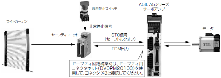
Connecting the host controller can configure a safety circuit that controls the safety functions.
When not constructing the safety circuit, use the supplied safety bypass plug.
Outline Description of Safe Torque Off (STO)
The safe torque off (STO) function is a safety function that shuts the motor current and turns off motor output torque by forcibly turning off the driving signal of the servo driver internal power transistor. For this purpose, the STO uses safety input signal and hardware (circuit).
When STO function operates, the servo driver turns off the servo ready output signal (S-RDY) and enters safety state.
This is an alarm condition and the 7-seg LED on the front panel displays the error code number.
Safety Precautions
- When using the STO function, be sure to perform equipment risk assessment to ensure that the system conforms to the safety requirements.
- Even while the STO function is working, the following potential safety hazards exist. Check safety in risk assessment.
- The motor may move when external force (e.g. gravity force on vertical axis) is exerted on it. Provide an external brake, etc., as necessary to secure the motor. Note that the purpose of motor with brake is holding and it cannot be used for braking application.
- When parameter Pr5.10 Sequence at alarm is set to free run (disable dynamic brake), the motor is free run state and requires longer stop distance even if no external force is applied. Make sure that this does not cause any problem.
- When power transistor, etc., becomes defective, the motor will move to the extent equivalent of 180 electrical angle (max.). Make sure that this does not cause any problem.
- The STO turns off the current to the motor but does not turn off power to the servo driver and does not isolate it. When starting maintenance service on the servo driver, turn off the driver by using a different disconnecting device.
- External device monitor (EDM) output signal is not a safety signal. Do not use it for an application other than failure monitoring.
- Dynamic brake and external brake release signal output are not related to safety function. When designing the system, make sure that the failure of external brake release during STO condition does not result in danger condition.
- When using STO function, connect equipment conforming to the safety standards.
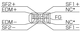
[Connector pin assignment]
(Viewed from cable)
* Do not connect anything to NC.
●System configuration
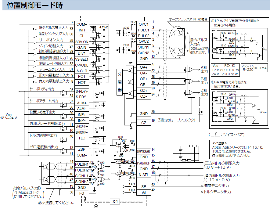
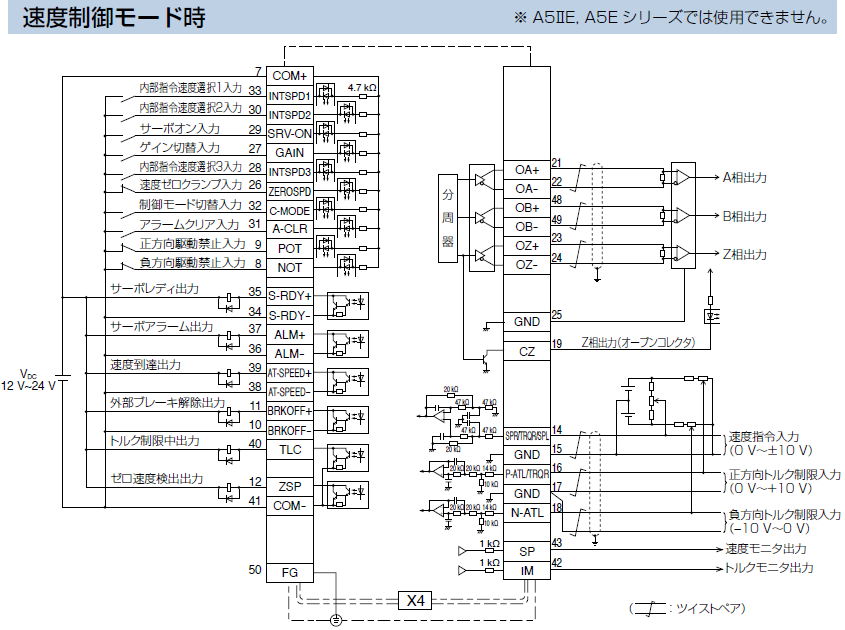
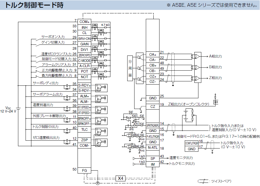
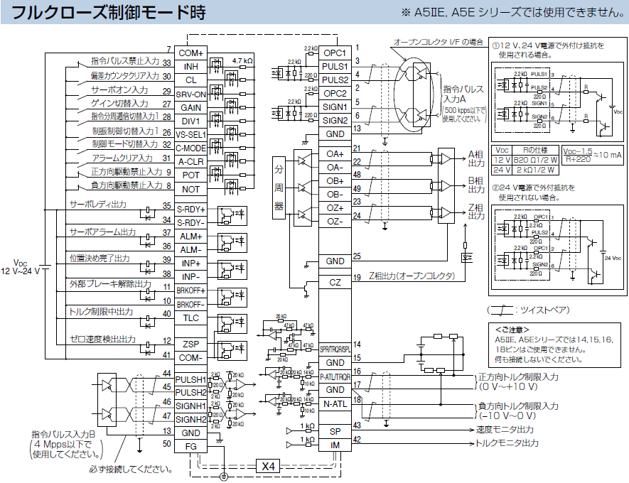
3.Control Circuit Diagram
Wiring to the Connector, X4
Note
Do not connect anythig to PIN No.14,15,16,18.
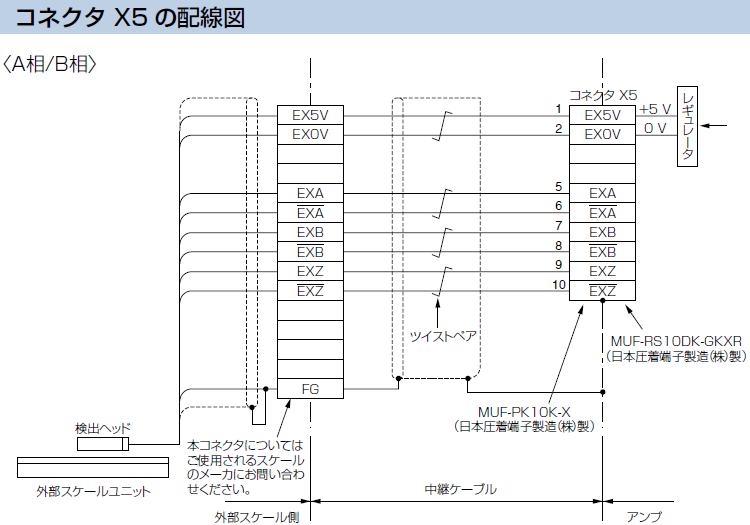
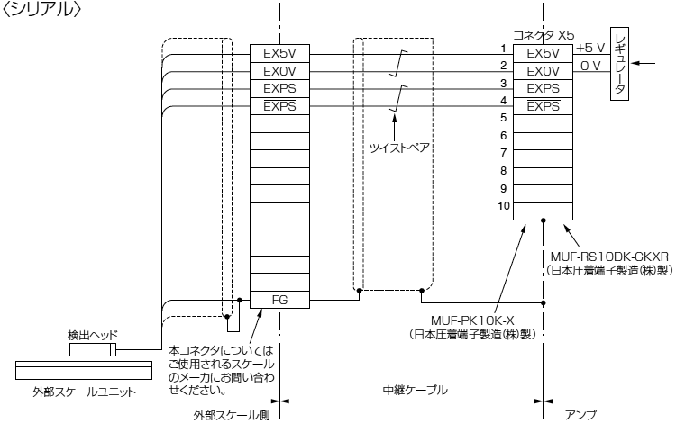
Wiring to the Connector, X5 (Excluding A5ⅡE, A5E series)
Applicable External Scale
The manufacturers applicable external scales for this product are as follows.
- DR. JOHANNES HEIDENHAIN GmbH
- Fagor Automation S.Coop
- Magnescale Co., Ltd.
- Mitutoyo Corporation
- NIDEC INSTRUMENTS CORPORATION
- Renishaw plc
* For the details of the external scale product, contact each company.
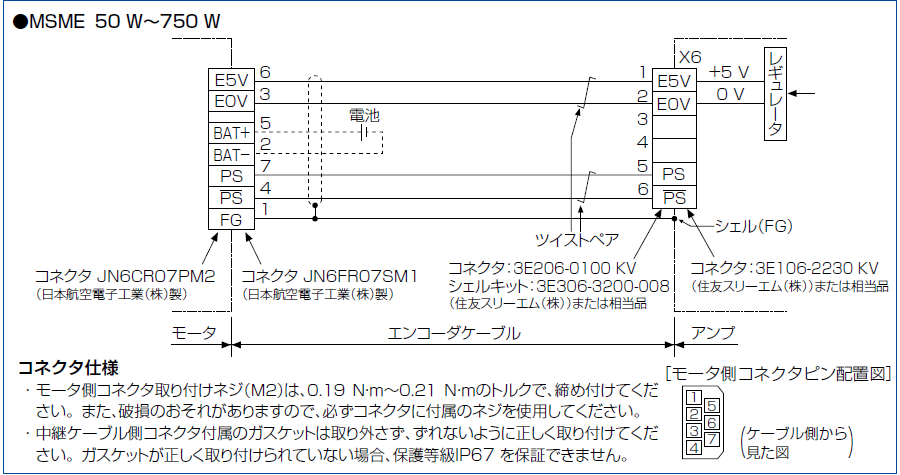
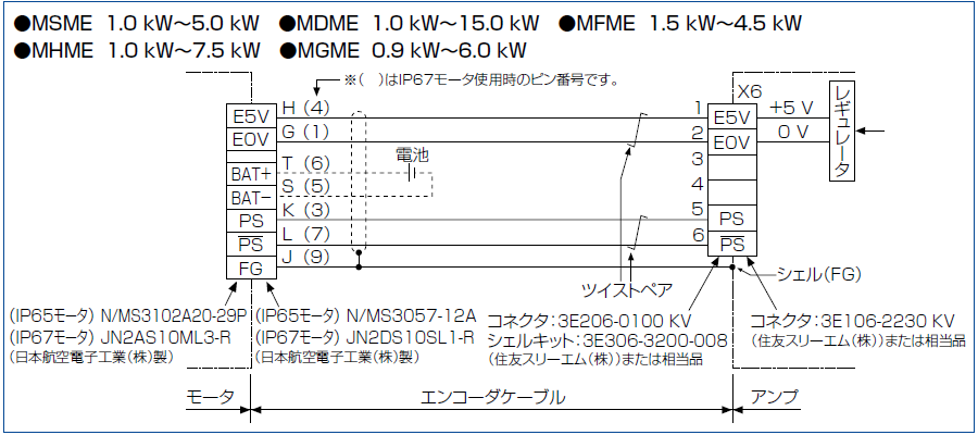
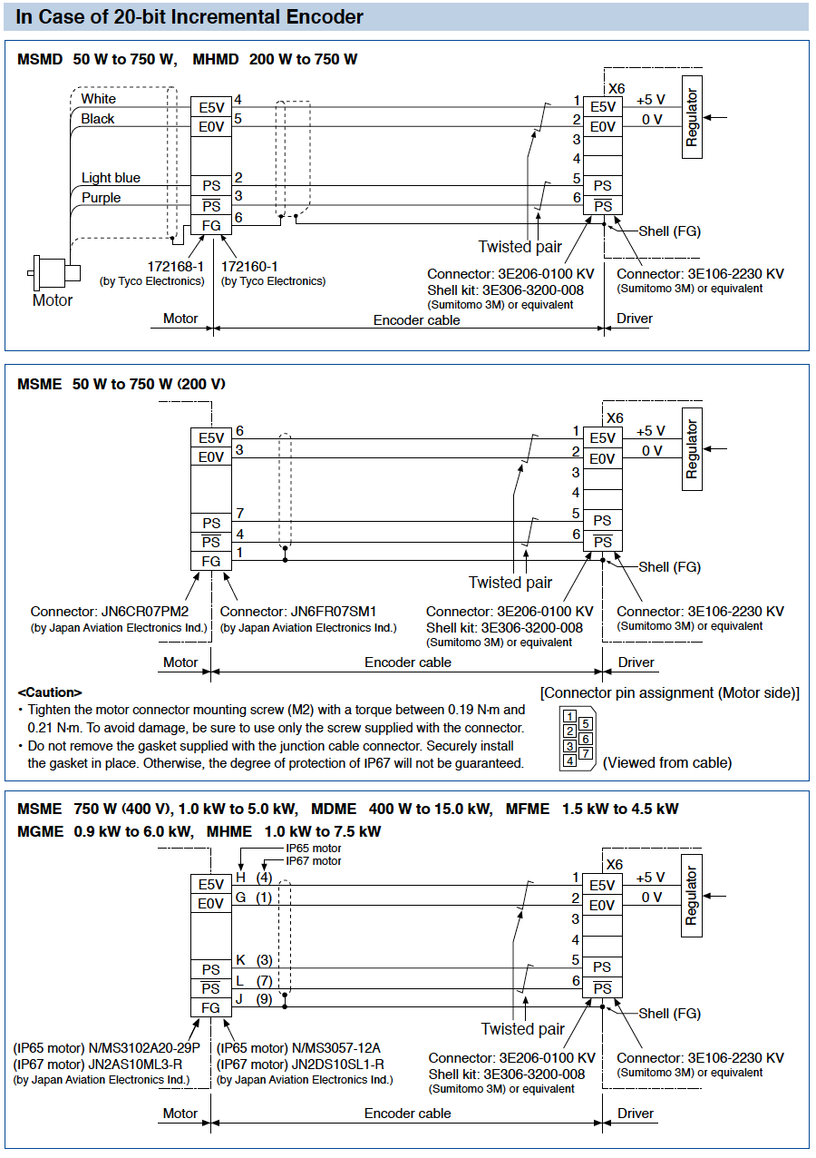
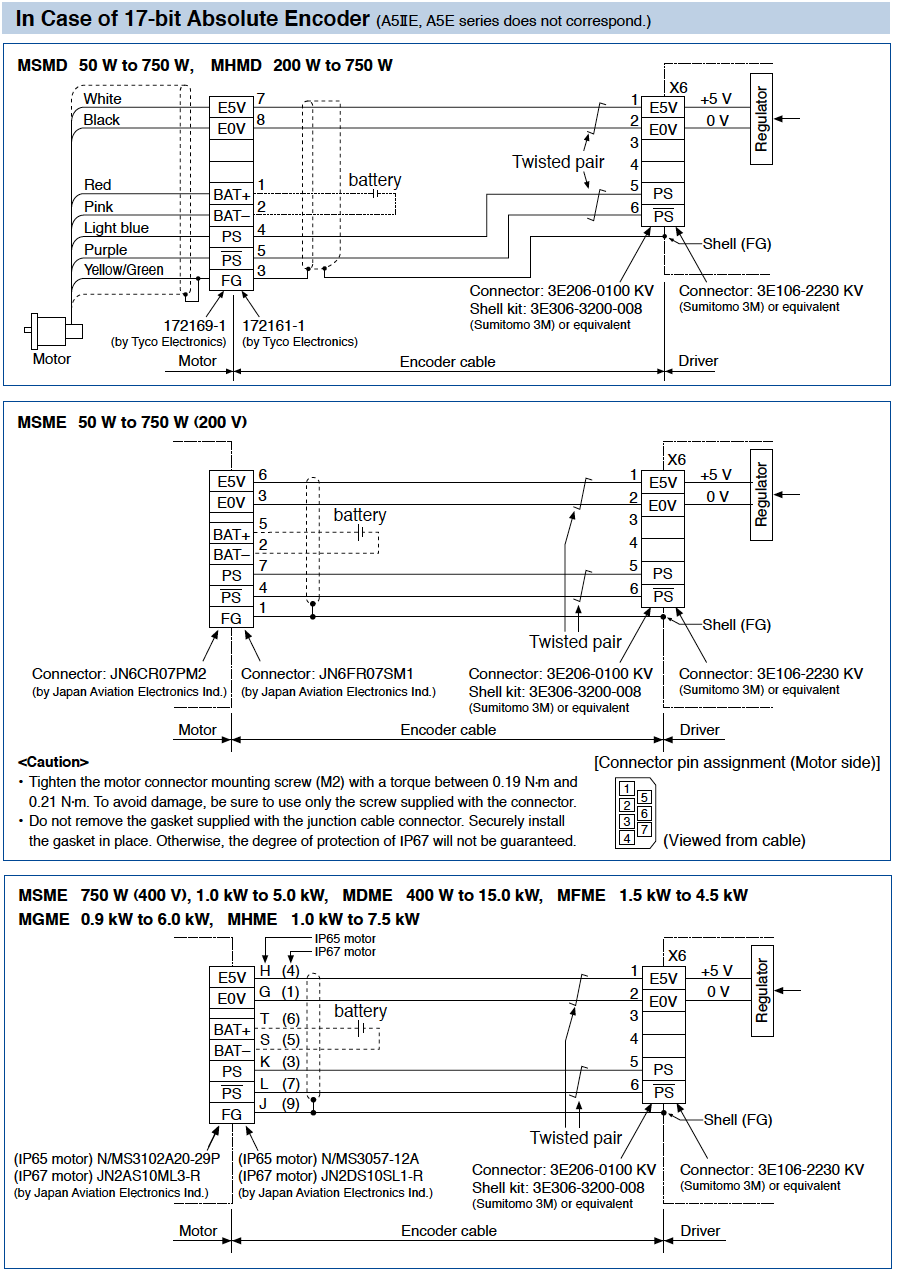
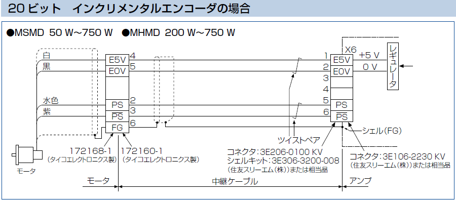
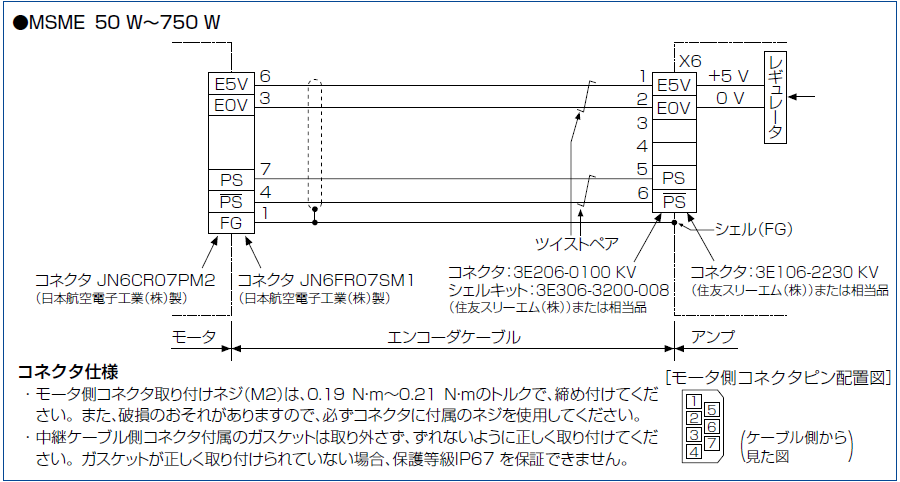
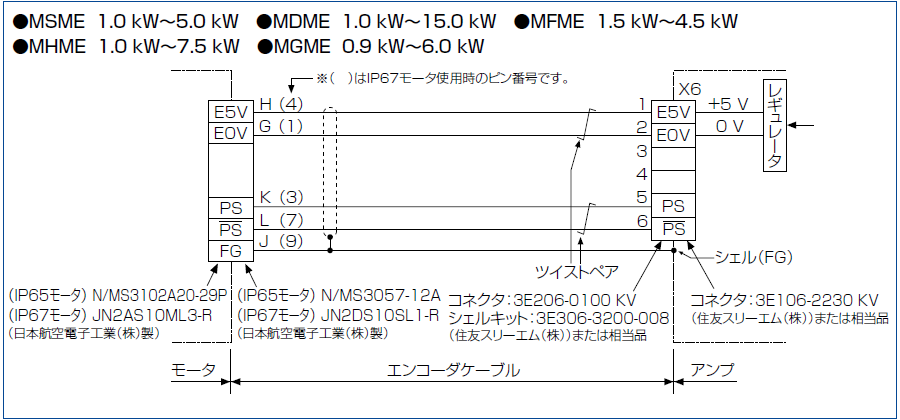
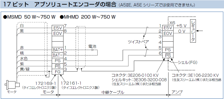
Wiring to the Connector, X6