基本資訊

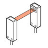
LED collimated beam type which is as accurate as a laser sensor, but much safer


Features
Safe red LED beam
Since a red LED, harmless to the eyes, has been incorporated as the beam source, you are free from strict laser safety regulations.
Moreover, due to the red LED beam source, the measuring spot is visible, which makes positioning of the object simple.

Compact size
Its emitter and receiver are much smaller compared to those of the amplifier built-in type (LA-510). Hence, they can be installed even in a narrow space inside an automatic assembly machine, etc.
Slim type / LA-305

- Emitter:
W18 x H40 x D10 mm
W0.709 x H1.575 x D0.394 in
- Receiver:
W18 x H40 x D10 mm
W0.709 x H1.575 x D0.394 in
Span & shift adjustment
For the analog output, in addition to the span adjustment function, a convenient shift function which enables the analog voltage to be shifted by ±0.5 V has been incorporated.
Example:
To shift the analog voltage from 2.51 V to 3.00 V with a certain amount of beam interruption

Simple beam alignment
Beam alignment is easy by using the target label (accessory). Further, the 3-stage stability indicators on the amplifier indicate the incident beam level at a glance.
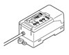
Option
| Designation | Model No. | Description |
|---|---|---|
| Digital panel controller (Note) | CA2-T2 | This is a very small controller which allows two independent threshold level settings. ・Supply voltage: 24 V DC ± 10 % ・Output: NPN open-collector transistor ・No. of inputs: 1 No. (sensor input) ・Input range: 1 to 5 V DC ・Main functions: Threshold value setting function, zero-adjust function, scale setting function, hysteresis setting function, start / hold function, auto-reference function, power supply ON-delay function, etc. |
Note :
If analog voltage output of LA-A1 is shifted, the input range may be exceeded. In that case, use CA2-T5 (input range ±10 V). Refer to the ultra-compact digital panel controller CA2 series.
Digital panel controller
CA2-T2

Order guide
Sensor heads
| Type | Appearance | Sensing range | Sensing width | Minimum sensing object | Model No.(Note) |
|---|---|---|---|---|---|
| Slim |
| 300mm 11.811 in | 5mm 0.197 in | ø0.05mm ø0.002 in opaque oblect | LA-305 |
Note:
The model No. with suffix "P" shown on the label affixed to the product is the emitter, "D" shown on the label is the receiver.
(e.g.) Emitter of LA-305: LA-305P, Receiver of LA-305: LA-305D
Amplifiers
Always use the sensor head and the amplifer together as a set.
| Type | Appearance | Model No. | Output |
|---|---|---|---|
| NPN output |
| LA-A1 | NPN open-collector transistor (Judgment output) Analog voltage ・Output voltage: 1 to 5 V |
Accessories
MS-LA3-2
(Sensor head mounting bracket for LA-305) (Note)
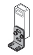
Two M3 (length 15 mm0.591 in) screws with washers are attached.Note: 2 sets are required to mount the emitter and the receiver.
Discontinued products
* Substitute products will not guarantee the specifications of discontinued products.
Please check the specification details from catalog before use.
| Discontinued product | Recommended substitute | ||||
|---|---|---|---|---|---|
| Product number/Part number | Last time buy | Product number/Part number | Product name | Remark | |
| Product number: LA-310 Part number: LA-310 | December 28, 2008 To be discontinued |
| Product number:- Part number:- | Ultra-compact Laser Collimated Beam Sensor HL-T1 | Suggested alternative products may be different under the conditions of use. |
| Product number: LA-A1P Part number: LA-A1P | September 30, 2017 To be discontinued |
| Product number:- Part number:- | - | Sorry, no suggested alternative products. |

Dimensions
- Unit: mm in
LA-305
Sensor head


LA-A1
Amplifier

MS-LA3-2
Sensor head mounting bracket for LA-305 (Accessory for LA-305)

Material:Cold rolled carbon steel (SPCC-P3)(Uni-chrome plated)Two M3 (length 15 mm0.591 in) screws with washers are attached.
Assembly dimensions

Discontinued products
LA-A1P
Amplifier

LA-310
Sensor head

I/O Circuit and Wiring diagrams
LA-A1
NPN output type

Symbols・・・
D1:Reverse supply polarity protection diode
D2:Input protection diode
ZD1, ZD2, ZD3 : Surge absorption zener diode
Tr1, Tr2 : NPN output transistor
Non-voltage contact or NPN open-collector transistor
External synchronization input (Voltage between ES+ and ES– )
Low: 0 to 1 V
High: +V or open
Notes:
1)When ES+ (pink) and ES– (pink/blue) of external synchronization input are connected, both HIGH and LOW comparative outputs are triggered in the mode selected by the external synchronization selection switch.
If the external synchronization function is not used, always short-circuit ES+ and ES– and set the external synchronization selection switch to gate trigger.
2)To use the analog output (gray), choose a device with an input impedance of 1 MΩ, or more, and connect the shield wire of the analog output to 0 V (common input) of the device.
3)Insulate all unused wires individually to avoid miscontact.
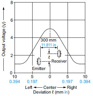
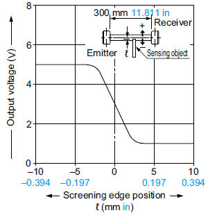
Sensing characteristics
LA-305
Slim type
Correlation between transverse deviation and output voltage
Correlation between interrupted beam width and output voltage
Correlation between ambient temperature and output voltage variation rate
