Discontinued Products
[Note]
The following applicable products and options are available continuously.
Standard components (8-core cable)
Extension cable
| Type | Appearance | Model No. | Description | ||
|---|---|---|---|---|---|
| With connectors on both ends | For emitter |
| SFB-CCJ3E | Length: 3 m 9.843 ft Net weight: 380 g approx. (2 cables) | Used for cable extension or connecting to the SF-C11 and the SF-C14EX control unit. One each for emitter and receiver Connector outer diameter: ø14 mm ø0.551 in max. Connector color: Gray (for emitter), Black (for receiver) Connector outer diameter: ø14 mm ø0.551 in max. |
| SFB-CCJ10E | Length: 10 m 32.808 ft Net weight: 1,200 g approx. (2 cables) | ||||
| For receiver | SFB-CCJ3D | Length: 3 m 9.843 ft Net weight: 190 g approx. (1 cables) | |||
| SFB-CCJ10D | Length: 10 m 32.808 ft Net weight: 1,200 g approx. (2 cables) | ||||

Muting control components (12-core cable, with interference prevention wire)
Extension cable
| Type | Appearance | Model No. | Description | ||
|---|---|---|---|---|---|
| With connector on one end |
| SFB-CC3-MU | Length: 3 m 9.843 ft Net weight: 430 g approx. (2 cables) | Used for connecting to an extension cable or the SF-C13 control unit. 2 cables/set for emitter and receiver Connector outer diameter: ø16 mm ø0.630 in max. | |
| SFB-CC7-MU | Length: 7 m 22.966 ft Net weight: 1,000 g approx. (2 cables) | ||||
| SFB-CC10-MU | Length: 10 m 32.808 ft Net weight: 1,300 g approx. (2 cables) | ||||
| With connectors on both ends | For emitter |
| SFB-CCJ3E-MU | Length: 3 m 9.843 ft Net weight: 190 g approx. (1 cables) | Used for connecting to an extension cable or the SF-C12 control unit. One each for emitter and receiver Connector color: Gray (for emitter), Black (for receiver) Connector outer diameter: ø16 mm ø0.630 in max. |
| SFB-CCJ10E-MU | Length: 10 m 32.808 ft Net weight: 660 g approx. (1 cable) | ||||
| For receiver | SFB-CCJ3D-MU | Length: 3 m 9.843 ft Net weight: 210 g approx. (1 cables) | |||
| SFB-CCJ10D-MU | Length: 10 m 32.808 ft Net weight: 680 g approx. (1 cable) | ||||


| Designation | Model No. | Description |
|---|---|---|
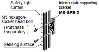
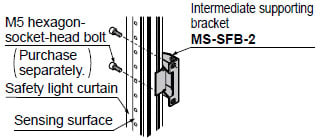
| Intermediate supporting bracket (Note 1) | MS-SFB-2 | Used to mount the safety light curtain in the intermediate position. (2 pcs. per set for emitter and receiver) Mounting is possible behind or at the side of the safety light curtain. |
| Test rod ø14 | SF4B-TR14 | Min. sensing object for regular checking (ø14 mm ø0.551 in), with finger protection type (min. sensing object ø14 mm ø0.551 in) |
| Test rod ø25 | SF4B-TR25 | Min. sensing object for regular checking (ø25 mm ø0.984 in), with hand protection type (min. sensing object ø25 mm ø0.984 in) |
Note : The number of sets required varies depending on the product.
1 set:
SF4B-F□<V2>...... Safety light curtain with 79 to 111 beam channels
SF4B-H□<V2>...... Safety light curtain with 40 to 56 beam channels
SF4B-A□<V2>...... Safety light curtain with 20 to 28 beam channels
2 sets:
SF4B-F127□<V2>
SF4B-H□<V2>...... Safety light curtain with 64 to 80 beam channels
SF4B-A□<V2>...... Safety light curtain with 32 to 40 beam channels
3 sets:
SF4B-H□<V2>....... Safety light curtain with 88 to 96 beam channels
SF4B-A□<V2>....... Safety light curtain with 44 to 48 beam channels
Intermediate supporting bracket
・MS-SFB-2
< In case of rear mounting >
< In case of side mounting >
Control units
| Designation | Appearance | Model No. | Application cable | Description | |
|---|---|---|---|---|---|
| Connector connection type control unit |
| SF-C11 | Bottom cap cable : SFB-CB□ Extension cable : SFB-CCJ□ | Use 8-core cable with connector to connect to the safety light curtain. Compatible with up to Control Category 4. Interference prevention wires and muting function cannot be used. | |
| Slim type control unit |
| SF-C13 | Bottom cap cable : SFB-CCB□(-MU) Extension cable : SFB-CC□(-MU) | Use a discrete wire cable to connect to the safety light curtain. Compatible with up to Control Category 4. Interference prevention wires and muting function can be used. | |


Note : Refer to "Exclusive Control Unit for Safety Light Curtain SF-C10 " for details of the exclusive control units.
Recommended safety relay
SF relay, slim type
SF series
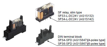
Note:Please contactour sales officefor details on the recommended products.
| Type | With LED indicator | |
|---|---|---|
| Model No. | SFS3-L-DC24V | SFS4-L-DC24V |
| Part No. | AG1S132 | AG1S142 |
| Contact arrangement | 3a1b | 4a2b |
| Rated nominal switching capacity | 6A/250V AC、6A/30V DC | |
| Min. switching capacity | 1mA/5V DC | |
| Coil rating | 15mA/24V DC | 20.8mA/24V DC |
| Rated power consumption | 360mW | 500mW |
| Operation time | 20ms or less | |
| Release time | 20ms or less | |
| Ambient temperature | -40 to +85 ℃ -40 to + 185 ℉ (Humidity: 5 to 85 % RH) | |
| Applicable certifications | UL/c-UL, TÜV, Korea S-mark | |
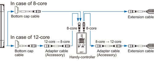
Handy-controller
| Designation | Appearance | Model No. |
|---|---|---|
| Handy-controller |
* Includes 2 adapter cables | SFB-HC |
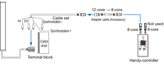
| Cable set for cable type connection |
| SFC-WNC1 |

Note : A handy-controller cannot be used with the SF4B-□-01<V2> and the SF-C14EX-01.
Pigtailed type
Cable type
Y-shaped connector
| Type | Appearance | Model No. | Description | |
|---|---|---|---|---|
| Wire-saving Y-shaped connector |
| SFB-WY1 (Note) | Wire-saving connector for standard components (8-core cable). Cables of emitter and receiver are consolidated into one cable for wire-saving. Wiring has +24 V, 0 V, OSSD 1, OSSD 2, output polarity setting wire (shield). Net weight: 35 g approx. [Power wire and synchronization wire are connected inside the connector. Interlock is disabled (automatic reset).] | |
| Cable with connector on one side |
| WY1-CCN3 (Note) | Cable length: 3 m 9.843 ft Net weight: 200 g approx. (1 cable) | Mating cable for Y-shaped connector Cable color: Gray (with black line) Connector color: Black The min. bending radius: R6 mm R0.236 in |
| WY1-CCN10 (Note) | Cable length: 10 m 32.808 ft Net weight: 620 g approx. (1 cable) | |||

Note : Not compatible with SF4B-□-01<V2>.
By using the Y-shaped connector, the least required wires such as power or safety output are consolidated into one cable. Man-hours taken for wiring is eliminated to the minimum. Construction times as well as wiring mistakes are greatly reduced.
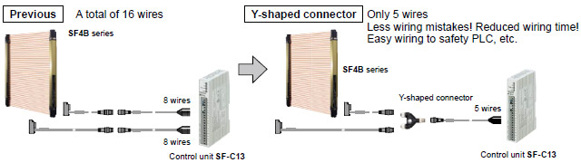
Refer to the instruction manual for more details such as installation of Y-shaped connector, terminal wiring, and wiring example.
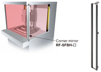
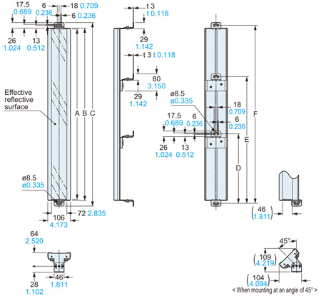
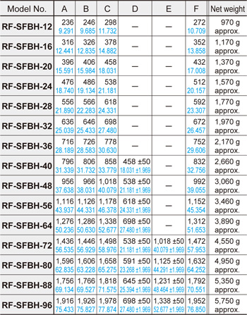
Corner mirror
| Designation | Corner mirror | |||
|---|---|---|---|---|
| Applicable beam channels | Model No. | Effective refl ective surface | ||
| Finger | Hand | Arm / Foot | ||
| 23 | 12 | 6 | RF-SFBH-12 | 236 x 72mm 9.291 x 2.835 in |
| 31 | 16 | 8 | RF-SFBH-16 | 316 x 72mm 12.441 x 2.835 in |
| 39 | 20 | 10 | RF-SFBH-20 | 396 x 72mm 15.591 x 2.835 in |
| 47 | 24 | 12 | RF-SFBH-24 | 476 x 72mm 18.740 x 2.835 in |
| 55 | 28 | 14 | RF-SFBH-28 | 556 x 72mm 21.890 x 2.835 in |
| 63 | 32 | 16 | RF-SFBH-32 | 636 x 72mm 25.039 x 2.835 in |
| 71 | 36 | 18 | RF-SFBH-36 | 716 x 72mm 28.189 x 2.835 in |
| 79 | 40 | 20 | RF-SFBH-40 | 796 x 72mm 31.339 x 2.835 in |
| 95 | 48 | 24 | RF-SFBH-48 | 956 x 72mm 37.638 x 2.835 in |
| 111 | 56 | 28 | RF-SFBH-56 | 1,116 x 72mm 43.937 x 2.835 in |
| 127 | 64 | 32 | RF-SFBH-64 | 1,276 x 72mm 50.236 x 2.835 in |
| - | 72 | 36 | RF-SFBH-72 | 1,436 x 72mm 56.535 x 2.835 in |
| - | 80 | 40 | RF-SFBH-80 | 1,596 x 72mm 62.835 x 2.835 in |
| - | 88 | 44 | RF-SFBH-88 | 1,756 x 72mm 69.134 x 2.835 in |
| - | 96 | 48 | RF-SFBH-96 | 1,916 x 72mm 75.433 x 2.835 in |
RF-SFBH-□
Normally for an L-shaped or U-shaped installation, 2 or 3 sets of safety light curtains are needed. With the use of a corner mirror reflecting the light, one set of safety light curtain is possible for L-shaped or U-shaped installation.
Operating range
| With 1 mirror | Declined to 90 % |
|---|---|
| With 2 mirrors | Declined to 80 % |
Others
| Designation | Model No. | Description |
|---|---|---|
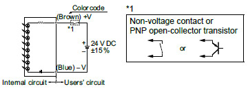
| Large display unit for safety light curtain | SF-IND-2 | With the auxiliary output of the safety light curtain, the operation is easily observable from various directions. Specifi cations ・Supply voltage: 24 V DC ±15 % ・Current consumption: 12 mA or less ・Indicators: Orange LED (8 pcs. used)[Light up when external contact is ON] ・Ambient temperature: –10 to +55 ℃ +14 to +131℉(No dew condensation or icing allowed) ・Material: POM (Enclosure), Polycarbonate (Cover), Cold rolled carbon steel (SPCC) (Bracket) ・Cable: 0.3mm2 2-core cabtyre cable, 3m 9.843 ft long ・Weight: 70 g approx. (including bracket) I/O circuit diagrams <With NPN output type>
<With PNP output type>
|
Dimensions
- Unit: mm in
SF4B-□<V2>
Safety light curtain
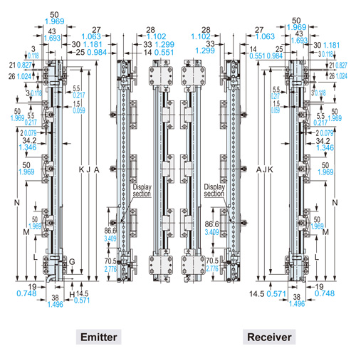
Assembly dimensions
Mounting drawing for the safety light curtains using the standard mounting brackets MS-SFB-1 (optional) and the intermediate supporting brackets.
<Rear mounting>
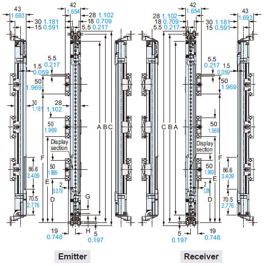
<Side mounting>
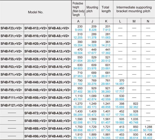
| Model No. | Protective height (Main body length) | Mount- ing pitch | Total length | Intermediate supporting bracket mounting pitch | ||||||
|---|---|---|---|---|---|---|---|---|---|---|
| A | A' (Note 1) | B | C | D | E | F | ||||
| SF4B-F□-01<V2> SF4B-H□-01<V2> | SF4B-A□-01<V2> | |||||||||
| SF4B-F23□ <V2> | SF4B-H12□ <V2> | SF4B-A6□ <V2> | 230 9.055 | 220 8.661 | 200 7.874 | 270 10.630 | 286 11.260 | - | - | - |
| SF4B-F31□ <V2> | SF4B-H16□ <V2> | SF4B-A8□ <V2> | 310 12.205 | 300 11.811 | 280 11.024 | 350 13.780 | 366 14.406 | - | - | - |
| SF4B-F39□ <V2> | SF4B-H20□ <V2> | SF4B-A10□ <V2> | 390 15.354 | 380 14.960 | 360 14.173 | 430 16.929 | 446 17.559 | - | - | - |
| SF4B-F47□ <V2> | SF4B-H24□ <V2> | SF4B-A12□ <V2> | 470 18.504 | 460 18.110 | 440 17.323 | 510 20.079 | 526 20.709 | - | - | - |
| SF4B-F55□ <V2> | SF4B-H28□ <V2> | SF4B-A14□ <V2> | 550 21.654 | 540 21.260 | 520 20.472 | 590 23.228 | 606 23.858 | - | - | - |
| SF4B-F63□ <V2> | SF4B-H32□ <V2> | SF4B-A16□ <V2> | 630 24.803 | 620 24.409 | 600 23.622 | 670 26.378 | 686 27.008 | - | - | - |
| SF4B-F71□ <V2> | SF4B-H36□ <V2> | SF4B-A18□ <V2> | 710 27.953 | 700 27.559 | 680 26.772 | 750 29.528 | 766 30.157 | - | - | - |
| SF4B-F79□ <V2> | SF4B-H40□ <V2> | SF4B-A20□ <V2> | 790 31.102 | 780 30.708 | 760 29.921 | 830 32.677 | 846 33.307 | 390 15.354 | - | - |
| SF4B-F95□ <V2> | SF4B-H48□ <V2> | SF4B-A24□ <V2> | 950 37.402 | 940 37.007 | 920 36.220 | 990 38.976 | 1,006 39.606 | 470 18.504 | - | - |
| SF4B-F111□ <V2> | SF4B-H56□ <V2> | SF4B-A28□ <V2> | 1,110 43.701 | 1,100 43.701 | 1,080 42.520 | 1,150 45.276 | 1,166 45.905 | 550 21.654 | - | - |
| SF4B-F127□ <V2> | SF4B-H64□ <V2> | SF4B-A32□ <V2> | 1,270 50.000 | 1,260 49.606 | 1,240 48.819 | 1,310 51.575 | 1,326 52.505 | 418 16.457 | 842 33.150 | - |
| - | SF4B-H72□ <V2> | SF4B-A36□ <V2> | 1,430 56.299 | 1,420 55.905 | 1,400 55.118 | 1,470 57.874 | 1,486 58.504 | 472 18.583 | 948 37.323 | - |
| - | SF4B-H80□ <V2> | SF4B-A40□ <V2> | 1,590 62.598 | 1,580 62.205 | 1,560 61.417 | 1,630 64.173 | 1,646 64.803 | 525 20.669 | 1,055 41.535 | - |
| - | SF4B-H88□ <V2> | SF4B-A44□ <V2> | 1,750 68.898 | 1,740 68.504 | 1,720 67.716 | 1,790 70.472 | 1,806 71.102 | 433 17.047 | 870 34.252 | 1,380 51.496 |
| - | SF4B-H96□ <V2> | SF4B-A48□ <V2> | 1,910 75.197 | 1,900 74.803 | 1,880 74.016 | 1,950 76.772 | 1,966 77.401 | 473 18.622 | 950 37.402 | 1,428 56.220 |
Note 1: When SF4B-□-01<v2> is used for China press machine as a safety device, the distance between the center of the 1st beam axis and the center of the last beam axis is regarded as protective height A’.
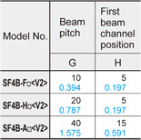
| Model No. | Beam pitch | First beam channel position |
|---|---|---|
| G | H | |
| SF4B-F□<V2> | 10 0.394 | 5 0.197 |
| SF4B-H□<V2> | 20 0.787 | 5 0.197 |
| SF4B-A□<V2> | 40 1.575 | 15 0.591 |
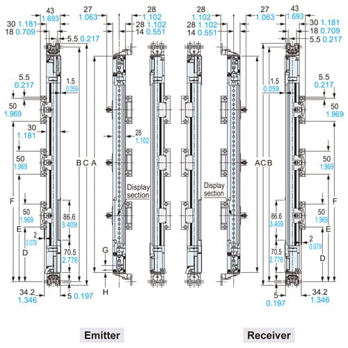
SF4B-□<V2>
Safety light curtain
Assembly dimensions
Mounting drawing for the safety light curtain on which the dead zoneless brackets MS-SFB-3 (optional) and the intermediate supporting brackets are mounted.
<Rear mounting]
<Side mounting>
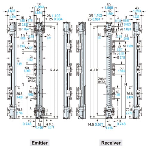
SF4B-□<V2>
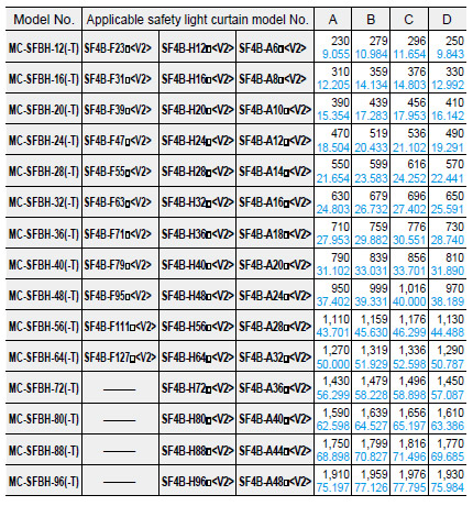
Protection bar set MC-SFBH-□ assembly dimensions
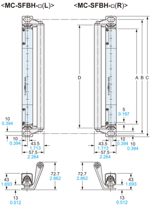
Material:Mounting bracket … Die-cast zinc alloyProtection bar … AluminumTwo brackets (one pc. each of R type and L type), one protection bar[Two pcs. each of M5 (length 16 mm0.630 in)hexagon-socket-head bolts, M5 (length 20 mm0.787 in)hexagon-socket-head bolt are attached.]
Protection bar set for rear / side mounting MC-SFBH-□-T assembly dimensions
[Rear mounting]
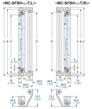
<Side mounting>
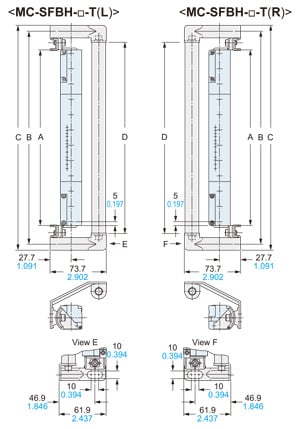
Material:
Mounting bracket … Iron (Trivalent chrome plated)
Protection bar … AluminumTwo brackets (one pc. each of R type and L type), one protection bar
[Two pcs. each of M5 (length 18 mm 0.709 in)hexagon-socket-head bolts, M5 (length 20 mm 0.787 in)hexagon-socket-head bolt are attached.]
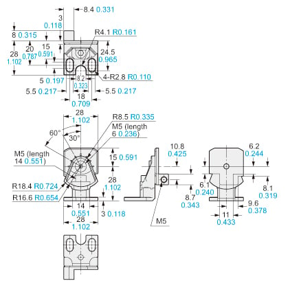
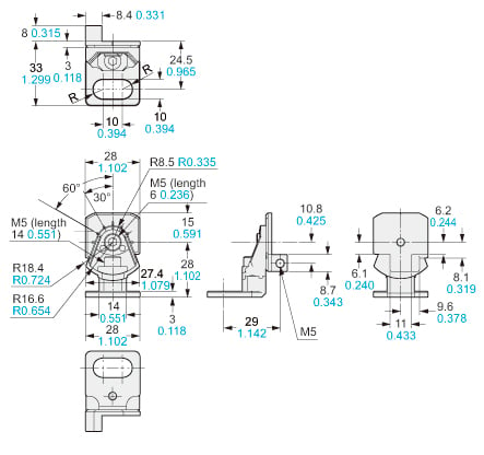
RF-SFBH-□
Corner mirror (Optional)
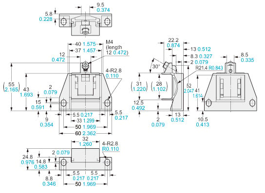
MS-SFB-1
Standard mounting bracket (Optional)
Material:
Die-cast zinc alloy
Four bracket set[Four M5 (length 18 mm 0.709 in) hexagon-socket-head bolts are attached]
MS-SFB-1-T
M8 Mounting bracket (Optional)
Material:
Die-cast zinc alloy
Four bracket set[Four M5 (length 18 mm 0.709 in) hexagon-socket-head bolts are attached.]
MS-SFB-2
Intermediate supporting bracket (Accessory for safety light curtain)
Material:
Die-cast zinc alloy
Note:The intermediate supporting bracket (MS-SFB-2) is enclosed with the following products. The quantity differs depending on the product as shown below:
1 set:
SF4B-F□<V2> … 79 to 111 beam channels
SF4B-H□<V2> … 40 to 56 beam channels
SF4B-A□<V2> … 20 to 28 beam channels
2 sets:
SF4B-F127<V2>SF4B-H□<V2> … 64 to 80 beam channels
SF4B-A□<V2> … 32 to 40 beam channels
3 sets:
SF4B-H□<V2> … 88 to 96 beam channels
SF4B-A□<V2> … 44 to 48 beam channels
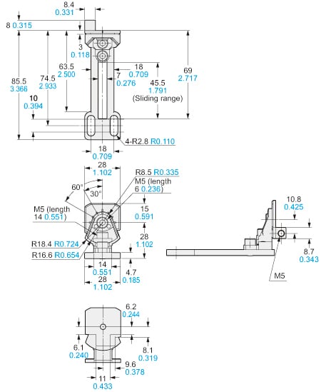
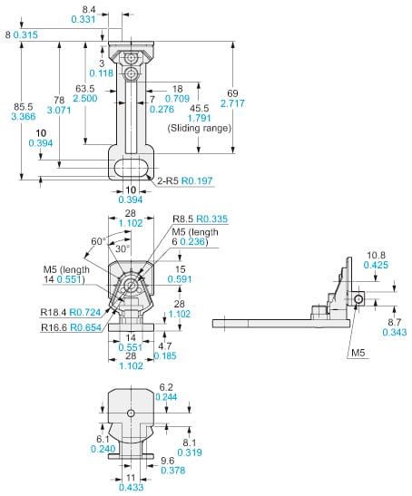
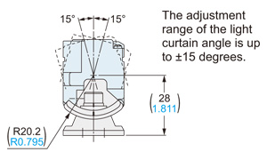
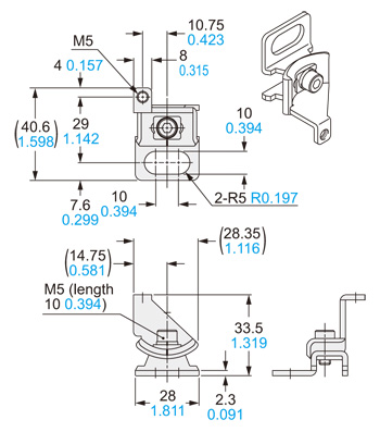
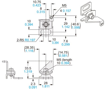
MS-SFB-3
Dead zoneless mounting bracket (Optional)
[Main body]
![MS-SFB-3 [Main body]](https://tp.industry.panasonic.com/hubfs/pid-corp/products/fasys/sensor/safety/sf4b_v2/size_figure/images/pic18.jpg)
Material:
Die-cast zinc alloy
Four bracket set[Four M5 (length 25 mm 0.984 in) hexagon-socket-head bolts and four spacers are attached.]
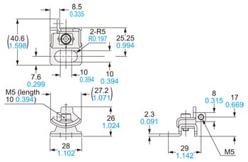
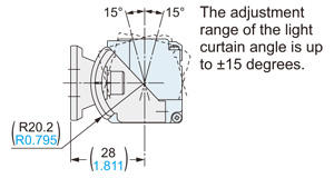
[L-shaped mounting]
![MS-SFB-3 [L-shaped mounting]](https://tp.industry.panasonic.com/hubfs/pid-corp/products/fasys/sensor/safety/sf4b_v2/size_figure/images/pic19.jpg)
[Mounting adjustment range]
The adjustment range of the safety light curtain angle is up to ±15 degrees
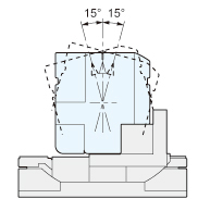
Note:The finger protection type has a beam pitch of 10 mm 0.394 in, which produces a dead zone. Additional measures will be required, such as using a protection cover.
MS-SFB-4
Pitch adapter bracket (Optional)
Material:
Die-cast zinc alloy
Four bracket set[Four M5 (length 18 mm 0.709 in) hexagon-socket-head bolts are attached]
MS-SFB-4-T
M8 pitch adapter bracket (Optional)
Material:
Die-cast zinc alloy
Four bracket set[Four M5 (length 18 mm 0.709 in) hexagon-socket-head bolts are attached]
MS-SFB-7-T MS-SFB-1-T2 (Rear mounting)
M8 rear mounting bracket (Optional) M8 rear / side mounting brackets set (Optional)
Material:
Iron (Trivalent chrome plated)
Four bracket set[Four M5 (length 18 mm 0.709 in) hexagon-socket-head bolts are attached.]
[Mounting adjustment range]
MS-SFB-8-T MS-SFB-1-T2 (Side mounting)
M8 side mounting bracket (Optional) M8 rear / side mounting brackets set (Optional)
[MS-SFB-8-T(R)]
[MS-SFB-8-T(L)]
[Mounting adjustment range]
Material:
Iron (Trivalent chrome plated)
Four bracket(two pcs. each of R type and L type) set
[Four M5 (length 18 mm 0.709 in) hexagon-socket-head bolts are attached.]
SFB-WY1
Y-shaped connector (Optional)
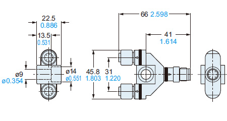
Net weight: 35 g approx.
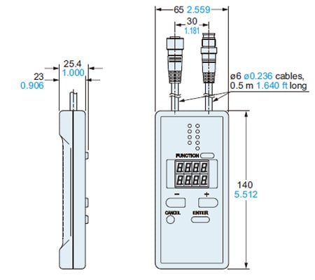
SFB-HC
Handy-controller (Optional)
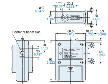
SF-LAT-2N
Laser alignment tool (Optional)
SF-IND-2
Large display unit for safety light curtain (Optional)
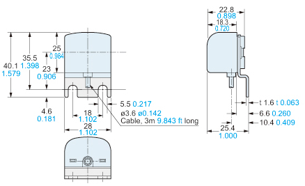
Material:
Bracket: Cold rolled carbon steel (SPCC) (Black chromate)
Enclosure: POM
Cover: Polycarbonate
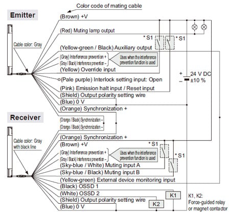
I/O Circuit and Wiring diagrams
I/O circuit diagram
<In case of using I/O circuit for PNP output>
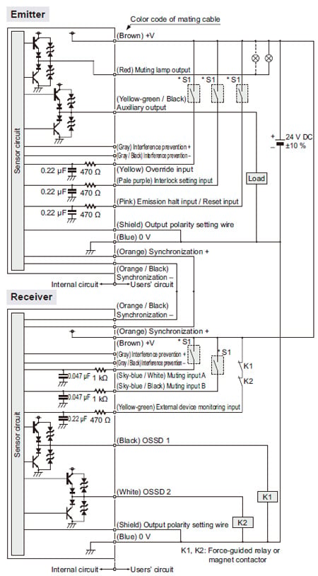
Note: The above diagram is when using a 12-core cable. If an 8-core cable is used, the red, yellow, gray, gray / black, sky-blue / white and sky-blue / black lead wires are absent.
*S1
Switch S1
・Emission halt input / Reset input
For manual reset
Vs to Vs – 2.5 V (sink current 5 mA or less): Emission halt (Note 1)
Open: Emission
For automatic reset
Vs to Vs – 2.5 V (sink current 5 mA or less): Emission (Note 1)
Open: Emission halt
・Interlock setting input, Override input, Muting input A / B,
External device monitoring input
Vs to Vs – 2.5 V (sink current 5 mA or less): Enabled (Note 1)
Open: Disabled
Note: Vs is the applying supply voltage.
<In case of using I/O circuit for NPN output>
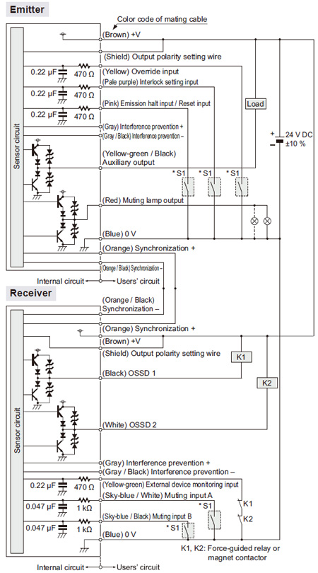
Note: The above diagram is when using a 12-core cable. If an 8-core cable is used, the red, yellow, gray, gray / black, sky-blue / white and sky-blue / black lead wires are absent.
*S1
Switch S1
・Emission halt input / Reset input
For manual reset
0 to +1.5 V (source current 5 mA or less): Emission halt
Open: Emission
For automatic reset
0 to +1.5 V (source current 5 mA or less): Emission
Open: Emission halt
・Interlock setting input, Override input, Muting input A / B,
External device monitor input
0 to +1.5 V (source current 5 mA or less): Enabled
Open: Disabled
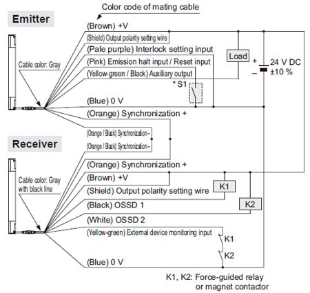
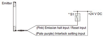
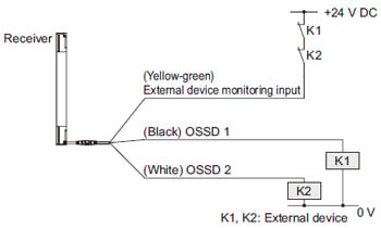
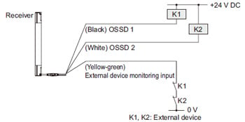
Connection example
Standard components (8-core cable): Interlock function “enabled (manual reset)”, external device monitoring function “enabled”
<In case of using I/O circuit for PNP output>
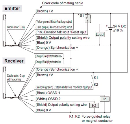
*S1
Switch S1
・Emission halt input / Reset input
For manual reset
Vs to Vs – 2.5 V (sink current 5 mA or less): Emission halt (Note)
Open: Emission
For automatic reset
Vs to Vs – 2.5 V (sink current 5 mA or less): Emission (Note)
Open: Emission halt
Note: Vs is the applying supply voltage.
The diagram at above shows the configuration when using PNP output, interlock function “enabled (manual reset)” and external device monitoring function “enabled”.
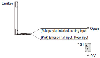
In case of setting the interlock function to “disabled (automatic reset)”
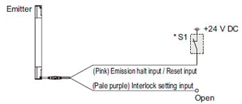
*Refer to the SF4B<V2> instruction manual for details of the interlock function.
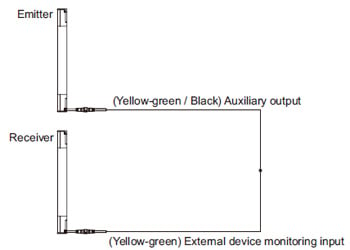
In case of setting the external device monitoring function to “disabled”
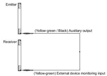
*Refer to the SF4B<V2> instruction manual for details of the external device monitoring function.
<In case of using I/O circuit for NPN output>
*S1
Switch S1
・Emission halt input / Reset input
For manual reset
0 to +1.5 V (source current 5 mA or less): Emission halt
Open: Emission
For automatic reset
0 to +1.5 V (source current 5 mA or less): Emission
Open: Emission halt
The diagram at above shows the configuration when using NPN output, interlock function “enabled (manual reset)” and external device monitoring function “enabled”.
In case of setting the interlock function to “disabled (automatic reset)”
*Refer to the SF4B<V2> instruction manual for details of the interlock function.
In case of setting the external device monitoring function to “disabled”
*Refer to the SF4B<V2>instruction manual for details of the external device monitoring function.
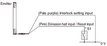
Connection example
Muting control components (12-core cable, with interference prevention wires): Interlock function “disabled (automatic reset)”, external device monitoring function “disabled”
<In case of using I/O circuit for PNP output>
*S1
Switch S1
・Emission halt input / Reset input
For manual reset
Vs to Vs – 2.5 V (sink current 5 mA or less): Emission halt (Note), Open: Emission
For automatic reset
Vs to Vs – 2.5 V (sink current 5 mA or less): Emission (Note), Open: Emission halt
・Override input, Muting input A / B, External device monitoring input
Vs to Vs – 2.5 V (sink current 5 mA or less): Enabled (Note), Open: Disabled
Note:
Vs is the applying supply voltage.
The diagram at above shows the configuration when using PNP output, interlock function “disabled (automatic reset)” and external device monitoring function “disabled”.
In case of setting the interlock function to “enabled (manual reset)”
- When the interlock function is “enabled (manual reset)”, the override function cannot be used.
*Refer to the SF4B<V2> instruction manual for details of the interlock function.
In case of setting the external device monitoring function to “enabled”
*Refer to the SF4B<V2> instruction manual for details of the external device monitoring function.
<In case of using I/O circuit for NPN output>

*S1
Switch S1
・Emission halt input / Reset input
For manual reset
0 to +1.5 V (source current 5 mA or less): Emission halt, Open: Emission
For automatic reset
0 to +1.5 V (source current 5 mA or less): Emission, Open: Emission halt
・Override input, Muting input A / B, External device monitoring input
0 to +1.5 V (source current 5 mA or less): Enabled, Open: Disabled
The diagram at above shows the configuration when using NPN output, interlock function “disabled (automatic reset)” and external device monitoring function “disabled”.
In case of setting the interlock function to “enabled (manual reset)”
- When the interlock function is “enabled (manual reset)”, the override function cannot be used.
*Refer to the SF4B<V2> instruction manual for details of the interlock function.
In case of setting the external device monitoring function to “enabled”
*Refer to the SF4B<V2> instruction manual for details of the external device monitoring function.
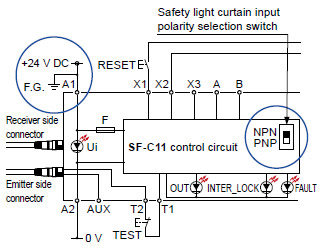
SF-C11
SF4B / SF4B-G series wiring diagram (Control Category 4)
For PNP output (minus ground)
- Set the safety light curtain input polarity selection switch to the PNP side and ground the 0 V line.
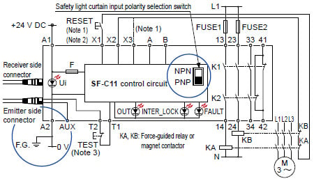
Notes:
1) The above diagram is when using manual reset. If automatic reset is used, disconnect the lead from X2 and connect it to X3. In this case, a reset (RESET) button is not needed.
2) Use a momentary-type switch as the reset (RESET) button.
3) Emission halt occurs when the test (TEST) button is open, and emission occurs when the test (TEST) button is short-circuited. If not using the test (TEST) button, short-circuit T1 and T2.
For NPN output (plus ground)
- In the above diagram, set the safety light curtain input polarity selection switch to the NPN side and ground the + side.
When SF-C11 is connected to the safety light curtain, be sure to use the following mating cable.
SFB-CB□, SFB-CCJ10□
Terminal arrangement diagram
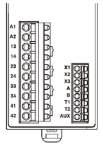
| Terminal | Function |
|---|---|
| A1 | +24 V DC |
| A2 | 0 V |
| 13-14, 23-24, 33-34 | Safety output (NO contact × 3) |
| 41-42 | Auxiliary output (NC contact × 1) |
| X1 | Reset output terminal |
| X2 | Reset input terminal (Manual) |
| X3 | Reset input terminal (Automatic) |
| A | Not used |
| B | |
| T1 | Test output terminal |
| T2 | Test input terminal |
| AUX | Semiconductor auxiliary output |
Pin layout for safety light curtain connectors
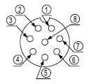
| Connector pin No. | Emitter side connector | Receiver side connector |
|---|---|---|
| ① | Interlock | OSSD 2 |
| ② | +24 V DC | +24 V DC |
| ③ | Emission halt | OSSD 1 |
| ④ | Auxiliary output | EDM (External relay monitor) |
| ⑤ | Synchronization wire + | Synchronization wire + |
| ⑥ | Synchronization wire – | Synchronization wire – |
| ⑦ | 0 V | 0 V |
| ⑧ | Shield wire | Shield wire |
SF-C12
SF4B / SF4B-G series wiring diagram (Control Category 4)
For PNP output (minus ground)
- Set the two safety light curtain input polarity select switches to the PNP side and connect the FG terminal to the 0 V line.
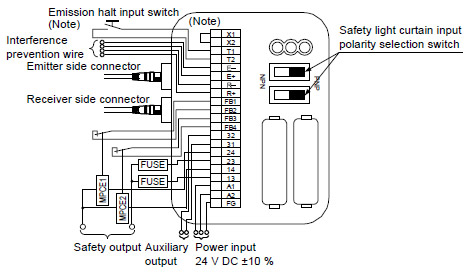
Note: The above diagram is when using manual reset. If automatic reset is used, connect a normally closed type pushbutton switch between T1 and T2 and leave between X1 and X2 open.
For NPN output (plus ground)
- In the above diagram, set the two safety light curtain input polarity selection switches to the NPN side and connect the F.G. terminal to the + side.
When SF-C12 is connected to the safety light curtain, be sure to use the following mating cable.
SFB-CB05-MU, SFB-CCJ10□-MU
Terminal arrangement diagram
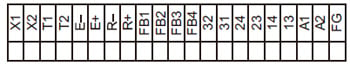
| Terminal | Function |
|---|---|
| FG | Frame ground (F.G.) terminal |
| A2 | 0 V |
| A1 | +24 V DC |
| 13-14, 23-24 | Safety output (NO contact × 2) |
| 31-32 | Auxiliary output (NC contact × 1) |
| FB4 | External relay monitor terminal 2 |
| FB3 | |
| FB2 | External relay monitor terminal 1 |
| FB1 |
| Terminal | Function |
|---|---|
| R+ | Interference prevention wire – (Receiver side) |
| R– | Interference prevention wire + (Receiver side) |
| E+ | Interference prevention wire – (Emitter side) |
| E– | Interference prevention wire + (Emitter side) |
| T2 | Emission halt input terminal |
| T1 | |
| X2 | Automatic reset / manual reset selection terminal Manual reset: X1 – X2 short-circuited |
| X1 |
Pin layout for safety light curtain connectors
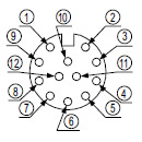
Note: Input and output for pin Nos. ⑪ and ⑫ are not used by this device.
| Connector pin No. | Emitter side connector | Receiver side connector |
|---|---|---|
| ① | Interlock | OSSD 2 |
| ② | +24 V DC | +24 V DC |
| ③ | Emission halt | OSSD 1 |
| ④ | Auxiliary output | EDM (External relay monitor) |
| ⑤ | Synchronization wire + | Synchronization wire + |
| ⑥ | Synchronization wire – | Synchronization wire – |
| ⑦ | 0 V | 0 V |
| ⑧ | Shield wire | Shield wire |
| ⑨ | Interference prevention wire + | Interference prevention wire + |
| ⑩ | Interference prevention wire – | Interference prevention wire – |
| ⑪ | (Override input) | (Muting input 1) |
| ⑫ | (Muting lamp output) | (Muting input 2) |
SF-C13
SF4B / SF4B-G series wiring diagram (Control Category 4)
For PNP output (minus ground)
- Connect the safety light curtain control outputs OSSD 1 and OSSD 2 to S1 and S2 respectively.
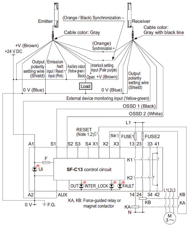
Notes:
1) The above diagram is when using manual reset. If automatic reset is used, disconnect the lead from X2 and connect it to X3. In this case, a reset (RESET) button is not needed.
2) Use a momentary-type switch as the reset (RESET) button.
For NPN output (plus ground)
- Connect the safety light curtain control outputs OSSD 1 and OSSD 2 to S4 and S2 respectively and ground the + side.
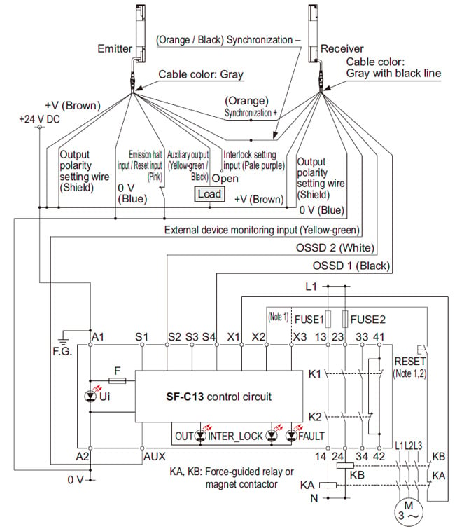
Notes:
1) The above diagram is when using manual reset. If automatic reset is used, disconnect the lead from X2 and connect it to X3. In this case, a reset (RESET) button is not needed.
2) Use a momentary-type switch as the reset (RESET) button.
When SF-C13 is connected to the safety light curtain, be sure to use the following descrete wire mating cable.
SFB-CCB□(-MU), SFB-CC□(-MU)
Terminal arrangement diagram
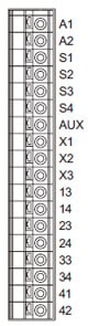
| Terminal | Function |
|---|---|
| A1 | +24 V DC |
| A2 | 0 V |
| S1 to S4 | Safety light curtain control output (OSSD) input terminal |
| AUX | Semiconductor auxiliary output |
| X1 | Reset output terminal |
| X2 | Reset input terminal (Manual) |
| X3 | Reset input terminal (Automatic) |
| 13-14, 23-24, 33-34 | Safety output (NO contact × 3) |
| 41-42 | Auxiliary output (NC contact × 1) |
A terminal block is required for wiring of safety light curtain side.
SF-C14EX(-01)
SF4B / SF4B-G series wiring diagram (Control Category 4)
For PNP output (minus ground)
- Set the output polarity selection switch to the PNP side and ground the 0 V line.
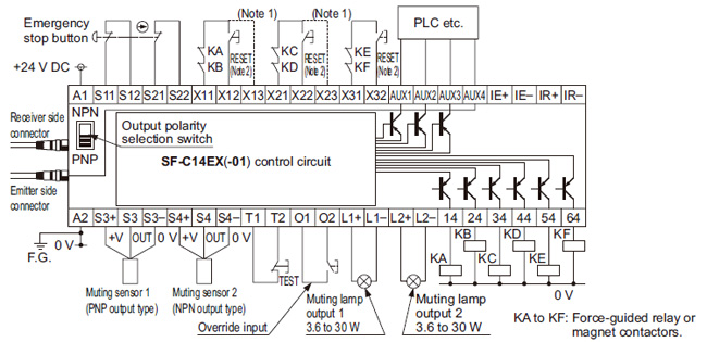
Notes:
1) The above diagram is when using manual reset.If automatic reset is used, disconnect the lead from X12 and connect it to X13,and disconnect the lead from X22 and connect it to X23, as shown by the dotted lines. In this case, a reset (RESET) button is not needed. Terminals X31 to X32 are for manual reset only.
2) Use a momentary-type switch for the reset (RESET) button.
For NPN output (plus ground)
- Set the output polarity selection switch to the NPN side and ground the side of the power supply input.
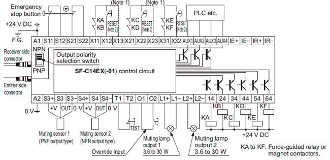
Notes:
1) The left diagram is when using manual reset. If automatic reset is used, disconnect the lead from X12 and connect it to X13, and disconnect the lead from X22 and connect it to X23, as shown by the dotted lines. In this case, a reset (RESET) button is not needed. Terminals X31 to X32 are for manual reset only.
2) Use a momentary-type switch for the reset (RESET) button.
・When SF-C14EX is connected to
the safety safety light curtain, be sure to
use the following mating cable.
SFB-CB□-EX, SFB-CCJ10□
・If the NO (Normally Open) contact
switch is used as a muting sensor,
if wire it as shown in the figure below.
・If the emergency stop button is
not used, short-circuit between the
terminals S11 to S12 and S21 to
S22 directly.
Terminal arrangement diagram
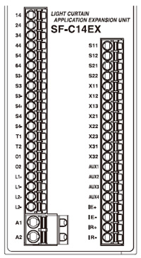
| Terminal | Function | Terminal | Function |
|---|---|---|---|
| 14 | Safety output 1, Beam received / Beam interrupted output of the safety light curtain | S11 | Emergency stop contact input 2 NC input Between S11 and S12 Between S21 and S22 |
| 24 | S12 | ||
| 34 | Safety output 2, safety light curtain output including the muting function | S21 | |
| 44 | S22 | ||
| 54 | Safety output 3 Emergency stop output | X11 | Safety output 1 reset input X11 - X12: Manual reset X11 - X13: Automatic reset |
| 64 | X12 | ||
| S3+ | Muting sensor input 1 (PNP output type) S3+, S3–: Power supply S3: Sensor output | X13 | |
| S3 | X21 | Safety output 2 reset input X21 - X22: Manual reset X21 - X23: Automatic reset | |
| S3– | X22 | ||
| S4+ | Muting sensor input 2(NPN output type) S4+, S4–: Power supply S4: Sensor output | X23 | |
| S4 | X31 | Safety output 3 reset input X31 - X32: Manual reset | |
| S4– | X32 | ||
| T1 | Test input terminal Open: Test mode Short-circuit: Normal operation | AUX1 | Auxiliary output 1, Muting output |
| T2 | AUX2 | Auxiliary output 2, Override output | |
| O1 | Override input terminal Open: Invalid Short-circuit: Valid | AUX3 | Auxiliary output 3, Blown lamp output |
| O2 | AUX4 | Auxiliary output 4, Safety light curtain auxiliary output | |
| L1+ | Muting lamp output 1 | IE+ | Interference prevention terminal, Emitter side + |
| L1– | IE– | Interference prevention terminal, Emitter side – | |
| L2+ | Muting lamp output 2 | IR+ | Interference prevention terminal, Receiver side + |
| L2– | IR– | Interference prevention terminal, Receiver side – | |
| A1 | +24 V DC | - | |
| A2 | 0 V | - | |
Pin layout for safety light curtain connectors
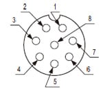
| Connector pin No. | Emitter side connector | Receiver side connector |
|---|---|---|
| ① | Interference prevention wire + | Interference prevention wire + |
| ② | +24 V DC | +24 V DC |
| ③ | Interference prevention wire – | Interference prevention wire – |
| ④ | Auxiliary output | Not used |
| ⑤ | Synchronization wire + | Synchronization wire + |
| ⑥ | Synchronization wire – | Synchronization wire – |
| ⑦ | 0 V | 0 V |
| ⑧ | Shield wire | Shield wire |
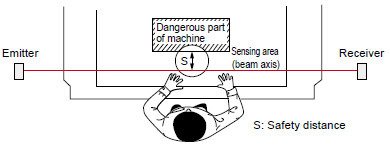
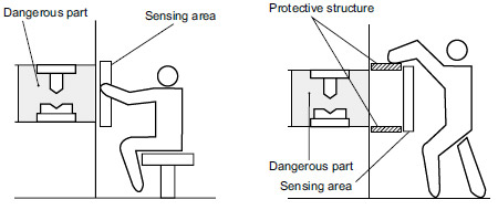
Example of correct sensing area setup
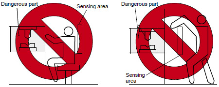
Example of incorrect sensing area setup
Safety distance