Basic Information
Less setup time for safety circuits


CE : Machinery Directive, EMC Directive
UKCA : Machinery Regulations, EMC Regulations
UL : Approved Listing
Features
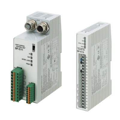
Quick-connection [SF-C11]
Connecting to the safety light curtain is done using plug-in connections, which shorten setup and replacement time.
![Quick-connection [SF-C11]](https://tp.industry.panasonic.com/hubfs/pid-corp/products/fasys/sensor/safety/sf-c10/images/pic05.jpg)
Easy setup requiring no torque control [SF-C11]
A spring method is used for the terminal blocks for connections other than to the safety light curtain. There is no need to control tightening torques for these terminal blocks.
![Easy setup requiring no torque control [SF-C11]](https://tp.industry.panasonic.com/hubfs/pid-corp/products/fasys/sensor/safety/sf-c10/images/pic06.jpg)
Removable terminal blocks reduce maintenance time [SF-C11]
Removable terminal blocks reduce the work required for reconnecting wiring during maintenance.
![Removable terminal blocks reduce maintenance time [SF-C11]](https://tp.industry.panasonic.com/hubfs/pid-corp/products/fasys/sensor/safety/sf-c10/images/pic07.jpg)
Slim design [SF-C13]
22.5 mm 0.886 in thickness, so it can even be inserted into narrow spaces inside panels.
![Slim design [SF-C13]](https://tp.industry.panasonic.com/hubfs/pid-corp/products/fasys/sensor/safety/sf-c10/images/pic09.jpg)
Supports both PNP and NPN polarities [All Models]
A single model can be used for PNP / NPN input switching, reducing the number of parts that are needed to be registered.
![Supports both PNP and NPN polarities [All Models]](https://tp.industry.panasonic.com/hubfs/pid-corp/products/fasys/sensor/safety/sf-c10/images/pic15.jpg)
Order guide
| Designation | Appearance | Model No. | Applicable cable (Note) | Description | |
|---|---|---|---|---|---|
| Connector connection type control unit (Supports presses used in Japan) |  | SF-C11 | <For connecting safety light curtain SF4D series> Bottom cap cable: SFD-CB□ Extension cable: SFB-CCJ□ (M12 connector) | Use 8-core cable with connector to connect to the safety light curtain. Muting function cannot be used. Compatible with up to Control Category 4. Supports presses used in Japan when combined with SF4D-□-01 (shearing machines not supported) | |
| Slim type control unit (Supports presses used in Japan) |  | SF-C13 | <For connecting safety light curtain SF4D series> Bottom cap cable: SFD-CCB□ Extension cable: SFD-CC□ | Use a discrete wire cable to connect to the safety light curtain. Muting function can be used. Compatible with up to Control Category 4. Supports presses used in Japan when combined with SF4D-□-01 (shearing machines not supported) | |
Note: Refer to instruction manual of safety light curtain to be connected.
Specifications
| Model No. | SF-C11 | SF-C13 | |
|---|---|---|---|
| Connectable safety light curtains | SF4D series | Safety light curtain manufactured by Panasonic Industry | |
| Applicable standards | EN 61496-1 (Type 4), EN 55011, EN ISO 13849-1: 2015 (Category 4, PLe), IEC 61496-1 (Type 4), ISO 13849-1: 2015 (Category 4, PLe), JIS B 9704-1 (Type 4), JIS B 9705-1 (Category 4), ANSI/UL 61496-1 (Type 4), UL 1998 (Class 2) | ||
| Applicable regulations and certifications | CE Marking (Machinery Directive, EMC Directive, RoHS Directive), UKCA Marking [Supply of Machinery (Safety) Regulations, EMC Regulations, RoHS Regulations], UL/c-UL Listing certification, TÜV SÜD certification | ||
| Supply voltage / Current consumption | 24 V DC ±10 % Ripple P-P 10 % or less / 100 mA or less (without safety light curtain) | ||
| Fuse rating | Built-in electronic fuse, Triggering current: 0.5 A or more, Reset after power down | ||
| Safety output | NO contact × 3 (13-14, 23-24, 33-34) | ||
| Utilization | AC-15, DC-13 (IEC 60947-5-1) | ||
| Rated operation voltage (Ue) / Rated operation current (le) | 30 V DC / 6 A, 230 V AC / 6 A, resistive load (For inductive load, during contact protection) Min. applicable load: 10 mA (at 24 V DC) (Note 2) | 30 V DC / 4 A, 230 V AC / 4 A, resistive load (For inductive load, during contact protection) Min. applicable load: 10 mA (at 24 V DC) (Note 2) | |
| Contact material / contacts | AgSnO, self cleaning, positively driven | ||
| Contact resistance | 100 mΩ or less (initial value) | ||
| Contact protection fuse rating | 6 A (slow blow) | 4 A (slow blow) | |
| Mechanical lifetime | 10,000,000 times or more (open/close frequency of 180 times/min) (Note 3) | ||
| Electrical lifetime | 100,000 times or more (open/close frequency of 20 times/min, 230 V AC, 3 A, using resistance load) (Note 3) | ||
| Pick-up delay (Auto reset/Manual reset) | 80 ms or less / 90 ms or less | ||
| Response time (Drop-out delay) | 10 ms or less | ||
| Auxiliary output | Safety relay contact (NC contact) ×1 (41-42) (Related to enabling path) | ||
| Rated operation voltage/current | 24 V DC / 2 A, Min. applicable load: 10 mA (at 24 V DC) | ||
| Contact protection fuse rating | 2 A (slow blow) | ||
| Semiconductor auxiliary output (AUX) | <Minus ground (Setting for PNP)> PNP open-collector transistor • Maximum source current: 60 mA • Applied voltage: same as supply voltage (between the auxiliary output and +V) • Residual voltage: 2.3 V or less (at 60 mA source current) • Leakage current: 2 mA or less <Plus ground (Setting for NPN)> NPN open-collector transistor • Maximum sink current: 60 mA • Applied voltage: same as supply voltage (between the auxiliary output and 0V) • Residual voltage: 1.5 V or less (at 60 mA sink current) • Leakage current: 2 mA or less | PNP open‑collector transistor • Maximum source current: 60 mA • Applied voltage: same as supply voltage (between the auxiliary output and +V) • Residual voltage: 2.3 V or less (at 60 mA source current) • Leakage current: 2 mA or less | |
| Output operation | Related to auxiliary output of safety light curtain | ON when the safety light curtain is interrupted | |
| Indicators | Power supply (Ui) | Green LED (lights up when the power is ON) | |
| Safety output [OUT] | Green LED (lights up when safety output is closed) | ||
| Interlock (INTER_LOCK) | Yellow LED (lights up when safety output is opened) | ||
| Fault (FAULT) | Yellow LED (blinks when fault occurs) | ||
| External relay monitor function | Incorporated | ||
| Trailing edge function | Incorporated | ||
| Polarity selection function (Note4) | Incorporated (Sliding switch allows selection of plus/minus ground) Minus ground: Correspond to PNP output safety light curtain Plus ground: Correspond to NPN output safety light curtain | Incorporated (Cable connection allows selection of plus/minus ground) Minus ground: Correspond to PNP output safety light curtain Plus ground: Correspond to NPN output safety light curtain | |
| Excess voltage category / Pollution degree | ll / 2 | ||
| Environmental resistance | Protection | Enclosure: IP40, Terminal: IP20 | |
| Ambient temperature | –10 to +55 ℃ +14 to +131 ℉ (No dew condensation or icing allowed), Storage: –25 to +70 ℃ –13 to +158 ℉ | ||
| Ambient humidity | 30 to 85 % RH, Storage: 30 to 95 % RH | ||
| Vibration resistance | Resistance / malfunction 10 to 55 Hz frequency, 0.35 mm 0.014 in amplitude in X, Y, and Z directions for twenty times each | ||
| B10D (Note 5) | Minimum load: 20,000,000, Maximum load: 400,000 | ||
| Mission time | 20 years | ||
| Connection terminal | Detachable spring-cage terminal | Spring-cage terminal | |
| Enclosure material | ABS | ||
| Weight | Net weight: 320 g approx. | Net weight: 200 g approx. | |
Notes:
1) Where measurement conditions have not been specified precisely, the conditions used were an ambient temperature of +20 ℃ +68 ℉.
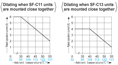
2) If several SF-C11 or SF-C13 units are being used in a line together, leave a space of 5 mm 0.197 in or more between each unit. If the units are touching each other, reduce the rated operating current for safety output in accordance with the ambient operating temperature as shown in the graphs below.
3) The life expectancy of the relay varies depending on the type of load, open / close frequency, ambient conditions and others.
4) Please switch the sliding switch to the PNP side for minus ground and to the NPN side for plus ground.
5) Mean cycle time that 10% of parts reach dangerous failure.
Discontinued products
| Model No. | SF-C12 | |
|---|---|---|
| Connectable safety light curtains | SF4B / SF4B-G series | |
| Applicable standards | EN 61496-1 (Type 4), EN 55011, EN ISO 13849-1 (Category 4, PLe), IEC 61496-1 (Type 4), ISO 13849-1 (Category 4, PLe), JIS B 9704-1 (Type 4), JIS B 9705-1(Category 4), ANSI/UL 61496-1 (Type 4) | |
| Applicable regulations | CE Marking (Machinery Directive, EMC Directive, RoHS Directive) | |
| Control category | ISO 13849-1 (EN ISO 13849-1, JIS B 9705-1) compliance up to Category 4, PLe standards | |
| Supply voltage / Current consumption | 24 V DC ±10 % Ripple P-P 10 % or less / 100 mA or less (without safety light curtain) | |
| Fuse rating | Built-in electronic fuse, Triggering current: 0.5 A or more, Reset after power down | |
| Safety output | NO contact × 2 (13-14, 23-24) | |
| Utilization | AC-15, DC-13 (IEC 60947-5-1) | |
| Rated operation voltage (Ue) / Rated operation current (le) | 24 V DC / 1 A, resistive load (For inductive load, during contact protection) Min. applicable load: 15 mA (at 24 V DC) | |
| Contact material / contacts | AgNiO + 0.2 μm 0.008 mil Au plating, self cleaning, positively driven | |
| Contact resistance | 50 mΩ or less (initial value) | |
| Contact protection fuse rating | 3 A (slow blow) | |
| Mechanical lifetime | 10,000,000 times or more (open/close frequency of 180 times/min) (Note 2) | |
| Electrical lifetime | 100,000 times or more (open/close frequency of 20 times/min, 230 V AC, 3 A, using resistance load) (Note 2) | |
| Pick-up delay (Auto reset/Manual reset) | 30 ms or less / 30 ms or less | |
| Response time | 14 ms or less | |
| Auxiliary output | Safety relay contact (NC contact) × 1 (31-32) (Related to enabling path) | |
| Rated operation voltage/current | 30 V DC / 3 A, Min. applicable load: 15 mA (at 24 V DC) | |
| Contact protection fuse rating | 3 A (slow blow) | |
| Semiconductor auxiliary output (AUX) | - | |
| Output operation | - | |
| Excess voltage category | III | |
| Indicators | Power supply (Ui) | Green LED (lights up when the power is ON) |
| Safety output [OUT (Note 3)] | Green LED (lights up when safety output is closed) | |
| Interlock (INTER_LOCK) | - | |
| Fault (FAULT) | Orange LED (lights up when two safety light curtain input polarity selection switch settings are different) | |
| External relay monitor function | Incorporated (Note 4) | |
| Trailing edge function | Incorporated | |
| Polarity selection function (Note 5) | Incorporated (Sliding switch allows selection of plus/minus ground) Minus ground: Correspond to PNP output safety light curtain Plus ground: Correspond to NPN output safety light curtain | |
| Pollution degree | 2 | |
| Protection | IP65 | |
| Ambient temperature | –10 to +55 ℃ +14 to +131 ℉ (No dew condensation or icing allowed), Storage: –25 to +70 ℃ –13 to +158 ℉ | |
| Ambient humidity | 35 to 85 % RH, Storage: 35 to 85 % RH | |
| Vibration resistance | Resistance 10 to 55 Hz frequency, 0.75 mm 0.030 in amplitude in X, Y, and Z directions for two hours each | |
| Connection terminal | European terminal | |
| Enclosure material | Die-cast aluminum | |
| Weight | Net weight: 1 kg approx. | |
Notes:
1) Where measurement conditions have not been specified precisely, the conditions used were an ambient temperature of +20 ℃ +68 ℉.
2) The life expectancy of the relay varies depending on the type of load, open / close frequency, ambient conditions and others.
3) The operation indicator is marked as "Enabling" on the unit for SF-C12.
4) Terminals for utilizing the functions of the SF4B / SF4B-G series are available.
5) Please switch the sliding switch to the PNP side for minus ground and to the NPN side for plus ground.
| Model No. | SF-C14EX(-01) (Note 2) | |
|---|---|---|
| Connectable safety light curtains | SF4B / SF4B-G series | |
| Applicable standards | IEC 61496-1 (Type 4), EN 55011, EN ISO 13849-1 (Category 4, PLe), IEC 61496 (Type 4), ISO 13849-1 (Category 4, PLe), JIS B 9704-1 (Type 4), JIS B 9705-1 (Category 4, PLe), ANSI/UL 61496-1 (Type 4), UL 1998 (Class 2) | |
| CE marking directive compliance | Machinery Directive, EMC Directive, RoHS Directive | |
| Control category | ISO 13849-1 (EN ISO 13849-1, JIS B 9705-1) compliance up to Category 4, PLe standards | |
| Supply voltage | 24 V DC ±10 % Ripple P-P 10 % or less | |
| Current consumption | 0.2 A or less (Excluding safety light curtain and other external connecting device) | |
| Safety outputs (Safety output 1 Safety output 2 Safety output 3) | PNP open-collector transistor 2 outputs × 3 or NPN open-collector transistor 2 outputs × 3 (selectable using a slider switch) <When PNP output is selected> • Maximum source current: 200 mA • Applied voltage: same as supply voltage (between the safety output and +V) • Residual voltage: 2 V or less (at 200 mA source current) <When NPN output is selected> • Maximum sink current: 200 mA • Applied voltage: same as supply voltage (between the safety output and 0 V) • Residual voltage: 2 V or less (at 200 mA sink current) | |
| Operation mode (Output operation) | Safety output 1: ON when the safety light curtain is in light receiving condition, OFF when the safety light curtain is in light interrupted condition (Note 3) Safety output 2: ON when the safety light curtain is in light receiving condition or the muting function is valid OFF when the safety light curtain is in light interrupted condition and the muting function is invalid (Note 3) Safety output 3: ON when the emergency stop is invalid, OFF when the emergency stop is valid | |
| Protection circuit (Short-circuit protection) | Incorporated | |
| Response time | OFF response: 14 ms or less (Safety output 1 and 2: including the response time of the safety light curtain) ON response: 90 ms or less (auto-reset) / 140 ms or less (manual reset) (Note 4) | |
| Auxiliary outputs [Auxiliary output 1 Auxiliary output 2 Auxiliary output 3 Auxiliary output 4 (Note 5)] | PNP open-collector transistor × 3 or NPN open-collector transistor × 3 (selectable using a slider switch) <When PNP output is selected> • Maximum source current: 60 mA • Applied voltage: same as supply voltage (between the auxiliary output and +V) • Residual voltage: 2 V or less (at 60 mA source current) <When NPN output is selected> • Maximum sink current: 60 mA • Applied voltage: same as supply voltage (between the auxiliary output and 0 V) • Residual voltage: 2 V or less (at 60 mA sink current) | |
| Operation mode (Output operation) | Auxiliary output 1: ON when the muting function is invalid, OFF when the muting function is valid Auxiliary output 2: ON when the override function is invalid, OFF when the override function is valid Auxiliary output 3: ON when the muting lamp is normal, OFF when the muting lamp is error Auxiliary output 4: ON when the safety light curtain is in light interrupted condition, OFF when the safety light curtain is in light receiving condition (Note 5) | |
| Protection circuit (Short-circuit protection) | Incorporated | |
| Muting lamp output | Applicable muting lamp: 24 V DC, 3.6 to 30 W (L1, L2 of each unit) | |
| Protection circuit (Short-circuit protection) | Incorporated | |
| PFHD (Note 6) | 1.66 × 10⁻¹⁰ | |
| MTTFD (Note 6) | 100 years or more | |
| Protection | Enclosure: IP40, Terminal: IP20 | |
| Ambient temperature | –10 to +55 ℃ +14 to +131 ℉ (No dew condensation or icing allowed), Storage: –25 to +70 ℃ –13 to +158 ℉ | |
| Ambient humidity | 30 to 85 % RH, Storage: 30 to 95 % RH | |
| Dielectric strength voltage | 1,000 V AC for one min. between all supply terminals connected together and enclosure | |
| Insulation resistance | 20 MΩ, or more, with 500 V DC megger between all supply terminals connected together and enclosure | |
| Vibration resistance | 10 to 55 Hz frequency, 0.35 mm 0.014 in double amplitude in X, Y and Z directions for two hours each | |
| Shock resistance | 30 G acceleration in X, Y and Z directions three times each | |
| Material | Enclosure: ABS | |
| Connection terminal | Detachable spring-cage terminal | |
| Weight | Net weight: 250 g approx. | |
Notes:
1) Where measurement conditions have not been specified precisely, the conditions used were an ambient temperature of +20 ℃ +68 ℉.
2) The handy-controller SFB-HC (optional) cannot be used with SF-C14EX-01.
3) Both safety output 1 and 2 are OFF when the emergency stop is valid regardless of whether the safety light curtain is in the light receiving or light interrupted condition.
4) The auto-reset cannot be used with safety output 3.
5) The auxiliary output incorporated in the SF4B / SF4B-G series is output.
6) PFHD: Probability of dangerous failure per hour, MTTFD: Mean time to dangerous failure (in years)
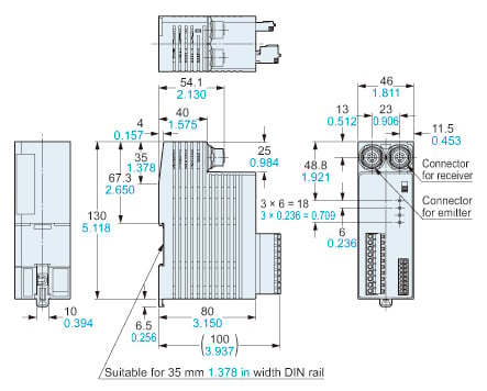
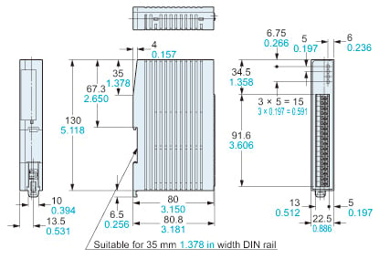
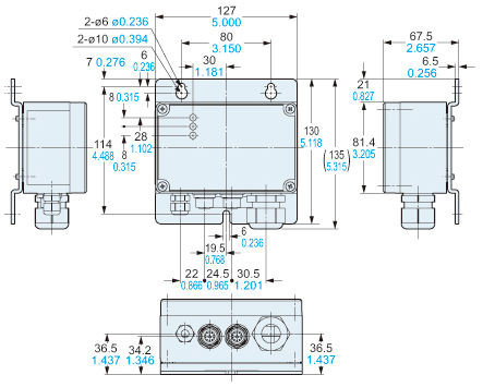
Dimensions
- Unit: mm in
SF-C11
Control unit (Optional)
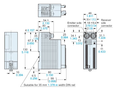
SF-C13
Control unit (Optional)
Discontinued products
SF-C12
Control unit (Optional)
SF-C14EX(-01)
Application expansion unit
I/O Circuit and Wiring diagrams
Terminal arrangement of SF-C11
When connecting the SF-C11 to the safety light curtains, make sure to use the 8-core connection cable with a connector.
Refer to the instruction manual of safety light curtain to be connected for details.
Terminal arrangement diagram
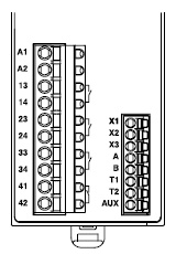
| Terminal | Function |
|---|---|
| A1 | +24 V DC |
| A2 | 0 V |
| 13-14, 23-24, 33-34 | Safety output (NO contact × 3) |
| 41-42 | Auxiliary output (NC contact × 1) |
| X1 | Reset output terminal |
| X2 | Reset input terminal (Manual) |
| X3 | Reset input terminal (Automatic) |
| A | Not used |
| B | |
| T1 | Test output terminal |
| T2 | Test input terminal |
| AUX | Semiconductor auxiliary output |
Pin layout for safety light curtain connectors
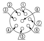
| Connector pin No. | Emitter side connector | Receiver side connector |
|---|---|---|
| ① | Interlock | OSSD 2 |
| ② | +24 V DC | +24 V DC |
| ③ | Emission halt | OSSD 1 |
| ④ | Auxiliary output | EDM (External relay monitor) |
| ⑤ | Synchronization wire + | Synchronization wire + |
| ⑥ | Synchronization wire – | Synchronization wire – |
| ⑦ | 0 V | 0 V |
| ⑧ | Shielded wire | Shielded wire |
Terminal arrangement of SF-C13
When connecting the SF-C13 to the safety light curtains, make sure to use a discrete wire connection cable. Refer to the instruction manual of safety light curtain to be connected for details.
Terminal arrangement diagram
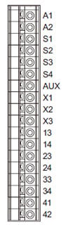
| Terminal | Function |
|---|---|
| A1 | +24 V DC |
| A2 | 0 V |
| S1 to S4 | Safety light curtain control output (OSSD) input terminal |
| AUX | Semiconductor auxiliary output |
| X1 | Reset output terminal |
| X2 | Reset input terminal (Manual) |
| X3 | Reset input terminal (Automatic) |
| 13-14, 23-24, 33-34 | Safety output (NO contact × 3) |
| 41-42 | Auxiliary output (NC contact × 1) |
When wiring the safety light curtain side, prepare a terminal block separately.
Cautions For Use
- This device has been developed / produced for industrial use only.
- When connecting this product to a product other than the connectable input device, the system does not conform to the control category 4 based on ISO 13849-1: 2015 (EN ISO 13849-1: 2015, JIS B 9705-1).
- The power supply unit of SF-C10 series uses the electronic fuse which does not require any replacement.
- When the electronic fuse trips, turn off the power supply and eliminate the cause for the overcurrent. After that, turn the power back on.
- The electronic fuse is not meant to be used for equipment that is operated continuously. Note that the specification may not be satisfied by continuous operation.
- Make sure to carry out the wiring in the power supply off condition.
- Wrong wiring will damage the product.
- Verify that the supply voltage variation is within the rating. Note that if a voltage exceeding the rated range is applied, or if an AC power supply is directly connected, the unit may get burnt or damaged.
- The DC power supply unit must satisfy the conditions given below:
1) Power supply unit authorized in the region where this device is to be used.
2) Use of the product as a unit in compliance with CE Marking: SELV (safety extra low voltage) / PELV (protected extra low voltage) power supply unit in conformity with EMC Directive and Low Voltage Directive.
3) Use of the product as a unit in compliance with UKCA Marking: SELV (safety extra low voltage) / PELV (protected extra low voltage) power supply unit in conformity with EMC Regulations and Low Voltage Regulations.
4) The frame ground (F.G.) terminal must be connected to ground when using a commercially available switching regulator.
5) Power supply unit with an output holding time of 20 ms or more.
6) If surges are likely to occur, take countermeasures such as connecting a surge absorber to the origin of the surge.
7) Power supply unit corresponding to CLASS 2 (only for requiring cULus Mark conformation) - Do not run the wires together with high-voltage lines or power lines or put them in the same raceway. This can cause malfunction due to induction.
- Avoid dust, dirt and steam.
- Take care that the product does not come in direct contact with oil, grease, or organic solvents, such as, thinner, etc.
- When using the product as a unit in compliance with CE Marking and UKCA Marking, make sure that the wires connected to the product do not exceed 30 m 98.43 ft in length.
- Note that this equipment is applicable only in the control circuit grounded in accordance with IEC 60204-1 and JIS B 9960-1, or in the control circuit in which the insulation monitor unit (ground fault detection unit) is included.
- This unit is suitable for indoor use only.
- The seal as shown in the drawing on the below is stuck to the engagement point of unit. If the seal is peeled off or broken, SF-C10 series will not be certified as “Safety equipment” and will not be covered by our guarantee.

Wiring
- The following solid wire and twisted wires (lead wire) are recommended.
SF-C11
Power supply and output line connector : 0.2 to 2.5mm2 (AWG24 to 12)
Signal line connector : 0.2 to 1.5mm2 (AWG24 to 16)
SF-C13
Single wire : ø0.4 to ø1.2mm ø0.016 to ø0.047 in (AWG26 to 16)
Twisted wire (lead wire) : 0.3 to 1.25mm2(AWG22 to 16)