Basic Information
Globally-compliant flameproof structure


CE : ATEX Directive, Machinery Directive, EMC Directive
UL, CSA : Certified by TÜV SÜD America Inc.
Features
■For your safety
In using the safety light curtain, please establish a control system to satisfy the below items in order to ensure safety with a total system.
>>Precautions for use
Complies with worldwide flameproof standards
The safety light curtain is built into a highly flameproof enclosure conforming to the IEC 61496 (Type 4).
The safety light curtain can be safely used in any workplace throughout the world where flameproof performance is required.
Europe : Complies with flameproof structures (Ex db [op is] ⅡB T6 Gb) specified by EN IEC 60079-0, EN 60079-1, EN 60079-28 and ATEX Directives (2014/34/EU).
United States : Complies with flameproof structures (Class I, Zone 1, AEx d ⅡB T6) specified by FM Class 3600, (ANSI/ISA.12.00.01, ANSI/ISA.12.22.01)
Canada : Complies with flameproof structures (Ex d ⅡB T6) specified by CAN/CSA-E60079-0.
China : Complies with flameproof structures (Ex db IIB T6 Gb) specified by GB/T 3836.1-2021(GB/T 3836.2-2021)
Japan : Complies with flameproof structures (Ex d ⅡB T6) according to technical standards conforming to international standards.
Hazardous locations: Zone 1 location, Zone 2 location
Classification of gas or vapor, and Temperature classification:IIB T6
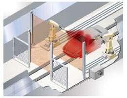
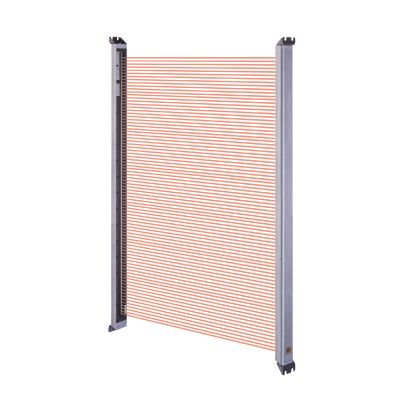
Ample protective height 1,595 mm 62.795 in
A single safety light curtain is sufficient for production lines with high working heights such as vehicle body spray-painting lines.

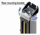
Mounting bracket enables easy beam-axis alignment
The beam-axis alignment is easy since angle adjustment is possible with the enclosed rear mounting bracket.
Less operating errors from extraneous light interference
A double-scanning method and retry processing are some unique new technology that help to avoid momentary interference from extraneous light coming from nearby equipment. A reduction in operating errors resulting from extraneous light interference can mean less frequent machinery stoppages and reduces the amount of time that a production line is not running.
Mutual interference is reduced without the need for interference prevention lines
No interference prevention lines are required between different items of equipment, so that safety light curtains can be installed with greater flexibility.
Order guide
Safety light curtain
| Type | Operating range (Note 1) | Model No. (Part No.) | Number of beam channels | Protective height (mm in) |
|---|---|---|---|---|
| 20mm 0.787in beam pitch | 0.3 to 6m 0.984 to 19.685 ft | BSF4-AH80 (UBSF4AH80V2) (Note 2) | 80 | 1,595 62.795 |
Notes:
1) The operating range is the possible setting distance between the emitter and the receiver.
2) The part number has been changed since December 2021.
Control unit
| Designation | Appearance | Model No. (Part No.) | Description |
|---|---|---|---|
| Slim type control unit |
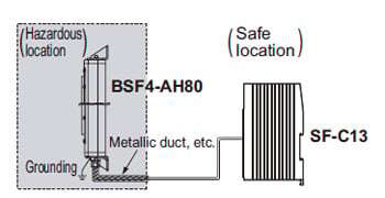
| SF-C13 (Note) (USFC13) | For PNP/NPN equivalent output type safety light curtain. Compatible with Control Category 4. Use in a safe location. |

Note:Refer to the SF-C10 series for details of SF-13.
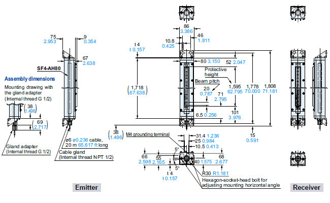
Dimensions
- Unit: mm in
I/O Circuit and Wiring diagrams
I/O circuit diagram
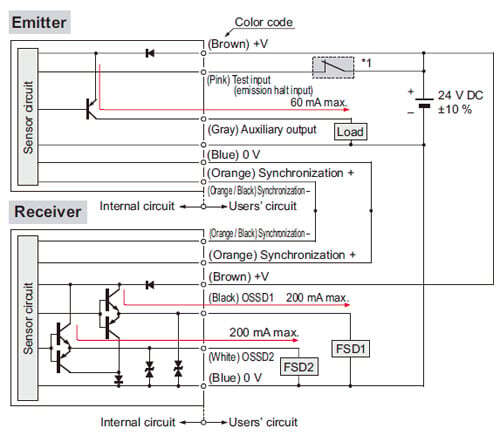
*1
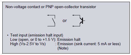
Notes:
1) Vs is same voltage as the voltage of the power supply to be used.
2) Ground the cable of shield without fail.
Wiring diagram of the SF-C13 (Control category 4)
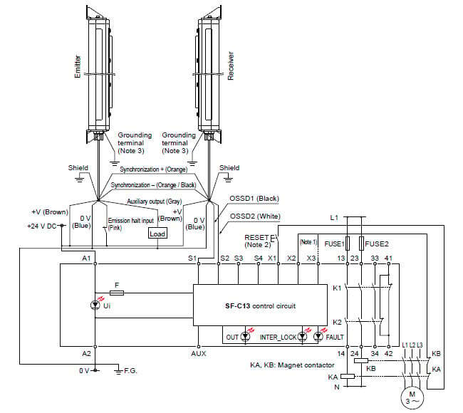
Notes:
1) The above diagram is when using manual reset.
If automatic reset is used, disconnect the read from X2 and connect it to X3.
In this case, a reset (RESET) button is not needed.
2) Use a momentary-type switch for the reset (RESET) button.
3) Ground the grounding terminal of BSF4-AH80 without fail.
SF-C13 Terminal arrangement diagram

- Use flameproof electric appliances that are compatible with hazardous locations (locations where an explosive atmosphere of gas or vapor may exist).
- Make sure that the power supply is off while wiring. Otherwise, electric shock may result.
- Never modify or repair the product yourself. Failure to follow this instruction may result in an explosion or ignition.
- Protect the cables, or external conductors, against possible external damage by passing them through a sufficiently strong metallic tube or by other means.
- Ground the grounding terminal without fail. Failure to follow this instruction may result in an explosion or ignition.
- Do not open the lid of the flameproof enclosure, and do not remove the window frame fixtures of the enclosure. Failure to follow this instruction may result in an explosion or ignition.
- The product can be used in the areas where flameproof appliances of “Groups IIA and IIB” and temperature classification “T1 to T6” can be used, and where explosive gases may exist.
Japan: Zone 1 and Zone 2
Europe: Zone 1 and Zone 2 (Category 2G: ATEX)
USA: Class I , Zone 1 and Class I , Zone 2 (US NEC 505)
Canada: Zone 1 and Zone 2
China: Zone 1 and Zone 2
- Install the product in a location where it is less likely to suffer mechanical damage.
Mounting
- When mounting the safety light curtain, secure it in place using four M10 bolts.
- The cable lead-in port is threaded for wiring protective tube or conduit (NPT 1/2). Using a steel wire tube etc., if necessary, screw a tube into the port at least five complete threads.
- After beam alignment, tighten the hexagon-socket-head bolts for adjusting mounting angle for fixing. The recommended tightening torque is 1.5 to 1.7 N·m. (The hexagon-socket-head bolts for adjusting mounting angle are on top and bottom surfaces of the emitter and receiver.)
Grounding
- Ground the external grounding terminal on the flameproof enclosure to keep the grounding resistance at or below 100 Ω.
- For grounding, use an electric wire with equivalent or higher insulation performance to a 600 V polyvinyl-insulated electric wire, and of a thickness ensuring safe carrying of the expected maximum ground current.
Others
- This device has been developed / produced for industrial use only.
- Use the device according to the specifications of this product. Failure to follow this instruction may result in electric shock, injuries, or damage to the product.
- Unpack the product with the right side facing up. If you do not follow this instruction, you may get injured.
- Do not touch any terminals when measuring the insulation resistance.
Failure to follow this instruction may result in electric shock. - If there is something abnormal with the product, immediately turn OFF the product. Otherwise, electric shock, injuries, or a fire may result.
- Before measuring the insulation resistance, confirm that there is no explosive atmosphere of gases or vapor around. Failure to follow this instruction may result in an explosion or ignition.
- Do not place anything in front of the nameplate.
- Do not remove the nameplate.
Reference
Classification of “Class” (North America only)
- Hazardous atmosphere is classified as follows.
| Classification | Hazardous atmosphere | Use of BSF4-AH80 |
|---|---|---|
| Class I | Gas or vapor | Can be used |
| Class II | Dust | Cannot be used |
| Class III | Fiber • Floating particles | Cannot be used |
Classification of hazardous locations “Zone”
| Classification | Hazardous atmosphere | Use of BSF4-AH80 |
|---|---|---|
| Zone 0 location | A location where a hazardous atmosphere exists continuously or for a long period of time (100 hours or longer per year) under normal conditions. | Cannot be used |
| Zone 1 location | A location where a hazardous atmosphere is expected to be generated under normal conditions (a location where a hazardous atmosphere is expected to exist for one to 100 hours per year). | Can be used |
| Zone 2 location | A location where a hazardous atmosphere is expected to be generated under abnormal conditions (a location where a hazardous atmosphere is expected to exist for less than one hour per year). | Can be used |
Classification of “Group”
- Electric appliances are classified into the following groups in terms of explosive atmospheres:
| Classification | Hazardous atmosphere | Use of BSF4-AH80 |
|---|---|---|
| Group I | Electric appliances for mines that are likely to generate firedamp. | Cannot be used |
| Group II | Electric appliances for locations with an explosive atmosphere, except for mines that are likely to generate firedamp. | Can be used |
Classification of gas / temperature in Group
- Excerpted from the “Guide to Explosion-proof Electric Machine and Appliance Type Verification (Related Technical Standards Consistent with Global Standards, Japan)”. In general, the temperature classes and gas or vapor categories of the representative explosive gases frequently used by plants are as shown in the table below:
| Temperature classification | T1 | T2 | T3 | T4 | T5 | T6 | |
|---|---|---|---|---|---|---|---|
| Flash point | Over 450 ℃ 842 ℉ | Over 300 ℃ 572 ℉, 450 ℃ 842 ℉ and below | Over 200 ℃ 392 ℉, 300 ℃ 572 ℉ and below | Over 135 ℃ 275 ℉, 200 ℃ 392 ℉ and below | Over 100 ℃ 212 ℉, 135 ℃ 275 ℉ and below | Over 85 ℃ 185 ℉, 100 ℃ 212 ℉ and below | |
| Classification of gas or vapor | A | Aceton Ammonia Carbon monoxide Ethane Acetic acid Ethyl acetate Toluene Propane Benzen Methanol Methane | Ethanol Vinyl acetate 1-butanol Butane Acetic anhydride | Octane Hexane | Acetaldehyde | ||
| B | Coal gas | Ethylene Ethylene oxide | |||||
| C | Water gas Hydrogen | Acetylene | Carbon disulfide | Ethyl nitrate | |||
Note: BSF4-AH80 can be used in the area of A to B (Classification of gas or vapor) and T1 to T6 (Temperature classification).