Basic Information

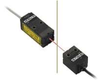
Ultra-compact sensor head
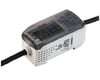
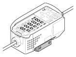
A high-functionality intelligent controller


FDA :HL-T□F only
-
【New products】
Thru-beam Type Digital Displacement Sensor HG-T

- Repeatability : 1 μm
- Ultra-slim : 8mm
- Wide-angle measurement : 10mm
Features
Ultra-compact sensor head
The ultra-compact size and yet the high level of performance. These sensors save space.
Resolution of 4 μm 0.157 mil
A high resolution of 4 μm 0.157 mil (at an average 64 cycles) allows high-precision positioning and size judgment.
Long sensing range
Long sensing range of 500 mm 19.685 in [HL-T1005A(F), HL-T1010A(F)] and 2 m 6.562 ft [HL-T1001A(F)] are available.
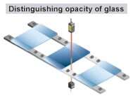
High-precision judgment even from minute differences in light intensity
The sensors are sensitive to minute differences in light intensity, so that they can judge even the opacity of glass.
In addition, the amount of light received can be displayed as a percentage to allow you to determine permeation rates.
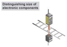
Minimum sensing object diameter ø8 μm ø0.315 mil [HL-T1001A(F)]
The laser with a beam diameter of ø1 mm ø0.039 in can sense extremely small objects with dimensions in micrometers such as bonding wires.
Adoption of a Class 1 laser
The adoption of a Class 1 laser (IEC / EN / JIS / GB) eliminates the need for safety countermeasures, so that these sensors can be used in photoelectric sensor applications with confidence.
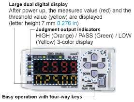
Fully equipped with convenient functionality
A wide range of convenient features has been incorporated into the unit's compact body: standard laser beam reception intensity setting / auto scaling setting / measurement processing (various timer and hold functions) / differentiation / monitor focus function.
These features make the unit useful for a wide variety of applications.
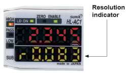
Detection resolution can be easily confirmed
The current resolution can be easily confirmed by setting the controller to indicate resolution display mode.
By displaying the resolution, the marginal increment can be easily determined for the threshold value setting, helping to accurately determine whether sensing can be performed.
3 types of teaching functions are now available
3 types of teaching functions are available: positioning teaching / 2-point teaching / automatic teaching, thus enabling a variety of applications to be accommodated for many different types of production sites.

Analog output is switchable between current / voltage
The analog output can be switched between either of two different outputs; current (4 to 20 mA) / voltage (±4 V). With the monitor focus function, the output can be adjusted over the range from -5 V to +5 V, or from 0 V to +5 V, facilitating connectivity with a variety of output devices.
Monitor focus function
The linear output is fully adjustable over the following range (current: 4 to 20 mA / voltage: ±4 V). The usage of the monitor focus function together with selectable current / voltage switching for the linear output allows for compatibility with a variety of output devices.
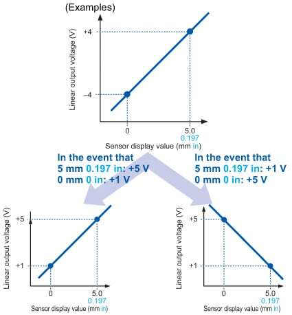
The linear output must be set by determining output values (maximum; current: 0 to 23.5 mA / voltage: ±5.5 V) at two different points, for the arbitrary display value.
FDA regulations conforming types are available
FDA regulations conforming types, most suitable for equipment used in the USA, are now available.
- FDA : Class II
- IEC / JIS / EN / GB : Class 1
Superior operability has been achieved
All settings can be easily performed by using the fourway keys and viewing the digital displays.
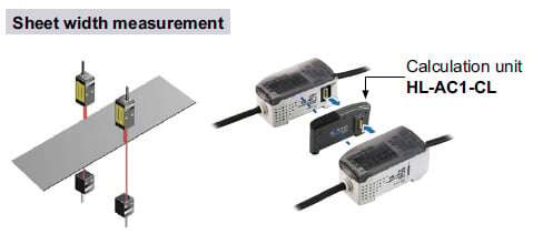
Calculations for 2 sensors are possible
The calculation unit (optional) just needs to be connected between the two controllers to enable calculations (addition and subtraction) to be carried out for two sensors. No digital panel controller is needed either.
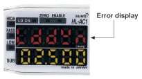
Self-check for laser diode deterioration
The intelligent controller performs self-checking for laser diode deterioration. If the controller detects significant deterioration (end of diode life), an error will be displayed on the main digital display panel. This function enables users to prepare in advance for potential laser diode malfunctions.


Order guide
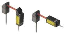
Sensor heads
| Type | Appearance | Sensing range | Sensing width | Min. sensing object | Conforming standards / regulations | Model No. |
|---|---|---|---|---|---|---|
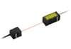
| Beam diameter ø1 mm ø0.039 in type |
| 2m 6.562 ft | ø1 mm ø0.039 in (ø1 to ø2.5mm ø0.039 to ø0.098 in at 500 to 2,000mm 19.685 to 78.740 in sensing range) | ø8 μm ø0.315 mil opaque object (ø50 μm ø1.969 mil opaque object at 500 to 2,000 mm 19.685 to 78.740 in sensing range) | IEC / EN / JIS / GB / KS | HL-T1001A |
| FDA / IEC / EN / JIS / GB | HL-T1001F | |||||
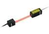
| Sensing width 5 mm 0.197 in type |
| 500mm 19.685 in | 5mm 0.197 in | ø0.05 mm ø0.002 in opaque object | IEC / EN / JIS / GB / KS | HL-T1005A |
| FDA / IEC / EN / JIS / GB | HL-T1005F | |||||
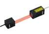
| Sensing width 10 mm 0.394 in type |
| 500mm 19.685 in | 10mm 0.394 in | ø0.1 mm ø0.004 in opaque object | IEC / EN / JIS / GB / KS | HL-T1010A |
| FDA / IEC / EN / JIS / GB | HL-T1010F |
Note :
The model No. with "P" shown on the label affixed to the product is the emitter, "D" shown on the label is the receiver.
Accessories
[Sensor mounting bracket for HL-T1001A(F) / HL-T1005A(F) (Note)]Two M3 (length 20 mm0.787 in) screws with washers are attached.Note: 2 sets are required to mount the emitter and receiver.
Sensor mounting bracket for HL-T1010A(F) (Note)Two M3 (length 25 mm0.984 in) screws with washers are attached.
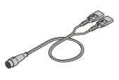
(Sensor head to controller connection cable)
Controllers
| Type | Appearance | Model No. | Output |
|---|---|---|---|
| NPN output |
| HL-AC1 | NPN open-collector transistor (Judgment output) Current / voltage output (Linear output) |
| PNP output | HL-AC1P | PNP open-collector transistor (Judgment output) Current / voltage output (Linear output) |
Calculation unit
| Appearance | Model No. |
|---|---|
| HL-AC1-CL |

Option
| Designation | Model No. | Description | |
|---|---|---|---|
| Side-view attachment | HL-T1SV1 | For HL-T1001A(F)/T1005A(F) (1 pc.) | The beam axis can be bent to a right angle making universal mounting possible. |
| HL-T1SV2 | For HL-T1010A(F) (1 pc.) | ||
| Controller mounting bracket | MS-HLAC1-1 | Use when mounting the controller with screws. | |
| Extension cable | HL-T1CCJ4 | Length: 4 m 13.123 ft Net weight: 162 g approx. | Extension cable for use between the controller and its cable linking it with the sensor head. Cabtyre cable with connectors on both ends Cable outer diameter: ø5.2 mm ø0.205 in Connector outer diameter: ø15.5 mm ø0.610 in max. |
| HL-T1CCJ8 | Length: 8 m 26.247 ft Net weight: 330 g approx. | ||
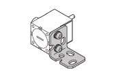
Side-view attachment
HL-T1SV1
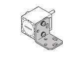
HL-T1SV2
Controller mounting bracket
MS-HLAC1-1
Extension cable
HL-T1CCJ4
HL-T1CCJ8

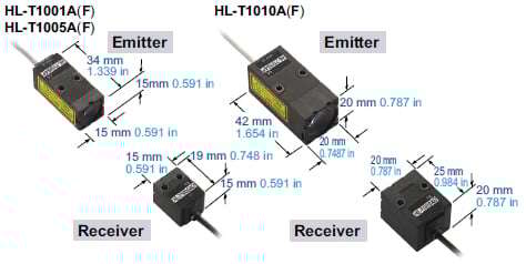
Dimensions
- Unit: mm in
HL-T1001A(F) HL-T1005A(F)
Sensor head
Emitter

Receiver

Notes:
1) IEC / EN / JIS / GB / KS conforming products do not contain light beam shielding plate, or certification / identification label.
2) The receiver of HL-T1001A(F) does not incorporate a slit.
HL-T1010A HL-T1010F
Sensor head
Emitter

Receiver

Note : IEC / EN / JIS / GB / KS conforming products do not contain light beam shielding plate, or certification / identification label.
HL-AC1 HL-AC1P
Controller Mounting drawing with a mounting bracket MS-HLAC1-1 (Optional)

HL-AC1-CL
Calculation unit (Optional)

MS-HLT1-1
Sensor head mounting bracket for HL-T1001A(F) / HL-T1005A(F)
[Accessory for HL-T1001A(F) / HL-T1005A(F)]

Material:Cold rolled carbon steel (SPCC) (Uni-chrome plated)Two M3 (length 20 mm0.787 in) screws with washers are attached.
Assembly dimensions
Mounting drawing with HL-T1005A's receiver

MS-LA3-1
Sensor head mounting bracket for HL-T1010A(F)
[Accessory for HL-T1010A(F)]

Material:Cold rolled carbon steel (SPCC) (Uni-chrome plated)Two M3 (length 25 mm0.984 in) screws with washers are attached.
Assembly dimensions
Mounting drawing with HL-T1010A's receiver

MS-HLAC1-1
Controller mounting bracket (Optional)

CN-HLT1-1
Sensor head to controller connection cable
(Accessory for sensor head)

HL-T1SV1
Side-view attachment for HL-T1001A(F) / HL-T1005A(F) (Optional)

Material:Polyetherimide (Enclosure), Glass (Front cover)Two M2 (length 6 mm0.236 in) screws with washers are attached.
Assembly dimensions
Mounting drawing with HL-T1005A's receiver

HL-T1SV2
Side-view attachment for HL-T1010A(F) (Optional)

Material:Polyetherimide (Enclosure), Glass (Front cover)Two M2 (length 6 mm0.236 in) screws with washers are attached.
Assembly dimensions
Mounting drawing with HL-T1010A's receiver

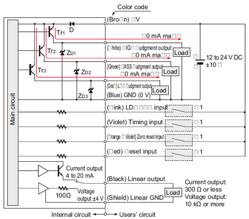
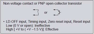
I/O Circuit and Wiring diagrams
HL-AC1
NPN output type
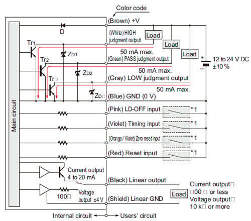
Symbols・・・
D: Reverse supply polarity protection diode
ZD1, ZD2, ZD3: Surge absorption zener diode
Tr1, Tr2, Tr3: NPN output transistor
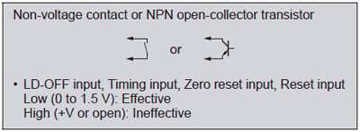
*1
HL-AC1P
PNP output type
Symbols・・・
D: Reverse supply polarity protection diode
ZD1, ZD2, ZD3: Surge absorption zener diode
Tr1, Tr2, Tr3: PNP output transistor
*1
Sensing characteristics
HL-T1001A HL-T1001F
Correlation between transverse deviation and output voltage

HL-T1005A HL-T1005F

HL-T1010A HL-T1010F

検出特性
HL-T1001A
HL-T1001F

HL-T1005A
HL-T1005F

HL-T1010A
HL-T1010F

- This product is a class 1 laser product according to IEC/EN/JIS/GB/KS and FDA regulations.
- Avoid observing beams in a dark surrounding environment.
- Do not look at beams using an optical device such as an optical telephoto system.
- Never attempt to disassemble, repair, or modify this product.
- The following label is affixed to this product. Handle the product according to the instruction given on the label.
(The English warning label based on FDA regulations is pasted on the FDA conformed type.)

Safety standards for laser beam products
- IEC : IEC 60825-1:2014
EN : EN 60825-1:2014/A11:2021
JIS : JIS C 6802:2014
GB : GB 7247.1-2012
KS : KS C IEC 60825-1:2014(HL-T1□□□A only)
Based on the above standards, the HL-T series are classified as Class 1 laser products.
Classification by IEC 60825-1
| Classification | Description |
|---|---|
| Class 1 | A laser that is safe when operated under operating conditions that can be reasonably foreseen. |
Note: When an unexpected failure occurs, dangerous radiation may be generated. Therefore, pay special attention to safety.
- For the purpose of preventing any injury which may occur to the user by the use of the laser product in advance, the following standards have been established by the IEC Standards, EN Standards, JIS Standards, GB Standards and FDA Regulations.
Safe use of laser products
- For the purpose of preventing users from suffering injuries by laser products, each standard stipulates (Safety of laser products). Kindly check the standards before use.
How to identify newer and older controllers
The controller for HL-T1 series, HL-AC1(P), has been upgraded from the shipment in July 1st, 2019.
- It can not be used new and previous controllers mixed when using with calculation unit, HL-AC1-CL.
- Some functions are different depending on the versions. Please refer to each new and previous manuals for functions in detail.
>>Go to "Manual download" page.
■How to distinguish the controllers
The serial No. on main unit and OS label will be changed as below.
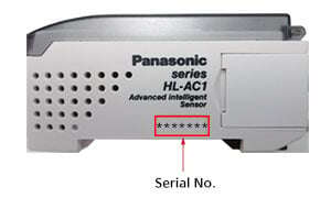
| Before the upgrade (Software Ver.2/Ver.1) | After the upgrade (Software Ver.3) |
|---|---|
| Serial No.:0******(It starts with 0.) | Serial No.:9******(It starts with 9.) |
Functions
| Function | Details |
|---|---|
| Zero reset function | The following tasks can be done by executing zero reset. |
| Auto scaling function | The auto scaling function selects whether to display the laser beam reception amount in the main-digital display in “mm” units or in “%” units, and determines whether the amount of laser beam received or the amount of laser beam interrupted is displayed. With the set standard laser beam reception amount as the reference value, the current laser beam reception amount (laser beam interrupted amount) is scaled automatically and is displayed as well as being output. |
| Standard received light setting | This function registers and stores the current laser beam reception amount in memory as the standard laser beam reception amount. The laser beam reception amount during full laser beam entry becomes the 100 % laser beam reception amount’s full scale (F.S.). If this function is used, the display and the linear output are set on the full scale (F.S.) automatically. It can also be used to correct the laser beam reception amount when there is a change in the laser beam reception amount due to dirt, etc. on the front glass. |
| Scaling function | The scaling function is a function that changes the display value to the desired amount with respect to the setting value. At the desired distance, the display value can be input and changed. |
| Hysteresis width setting function | This function sets the hysteresis to the desired value. |
| Monitor focus function | With this function, the linear output range and inclination, etc. with respect to the display value can be specified. Setting is done by determining the 2 output values with respect to the desired display values. |
| Differential function | This function makes the amount of change in the measured value an output value. Use this function when measuring if you are paying attention to changes in measured values, as when counting the number of workpieces, etc. |
| Display reverse function | The digital display’s direction can be selected. The forward direction or the reverse direction to match the direction of installation on the equipment can be selected. |
| ECO display function | This function makes the display dark and saves electric power. |
| Display digits limitation function | This determines the number of display digits in the main-digital and sub-digital displays. If the number of digits is limited, the digits are turned off beginning with the lowest order digit. |
| Zero reset memory function | This selects whether or not to save the zero reset level in memory when the power is turned OFF. If you desire to reproduce the zero reset level from the previous operating session when you turn the power ON again, then enable this function. If this function is enabled, the zero reset level data are written into the EEPROM each time. |
| Key lock function | The controller’s key input can be disabled. Once the key input is disabled, the controller will not accept any key inputs until the key lock is released. Use this function to avoid changing the setting by mistake. |
・The display value can be set at “0”.
・The linear output when the display reads “0” is made the center output value of the 2 points set by monitor focus. (In the default state, the current output is 12 mA and the voltage output is 0 V.)
Connection
- This product is made to satisfy the specifications when the sensor head is combined with the controller. In any other combination, not only may it not satisfy the specifications, but could be the cause of breakdown. So by all means, use it so that there is a combination of the sensor head and the controller.
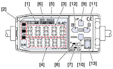
Functional description
| Description | Function | |
|---|---|---|
| [1] | Laser emitting indicator (LD ON) (Green LED) | Lights up when the sensor head is emitting laser beam. |
| [2] | Judgment output indicators (HIGH / PASS / LOW) (Orange / Green / Yellow LED) | HIGH: Orange LED (lights up when measured value > HIGH threshold value) PASS: Green LED ( lights up when HIGH threshold value ≥ measured value ≥ LOW threshold value) LOW: Yellow LED (lights up when LOW threshold value > measured value) |
| [3] | Main digital display (5 digit red LED) | When in the RUN mode, it displays the measured value (mm/%). During measurement hold, it displays the hold value (mm/%). In Reverse mode, the top and bottom are displayed in reverse. |
| [4] | Sub-digital display (5 digit yellow LED) | When in the RUN mode, it displays the threshold value, voltage / current value, light reception amount or resolution. When in the THR mode, it displays the respective threshold values. In reverse mode, the top and bottom are displayed in reverse. |
| [5] | Enable indicator (ENABLE) (Green LED) | Lights up when operation is normal. Goes off when operation is abnormal (if the sensor head is not connected when the power is turned on). |
| [6] | Zero reset indicator (ZERO) (Green LED) | Lights up when the zero reset function is enabled. |
| [7] | Mode selection switch | The following 3 modes can be selected. • RUN mode: Measuring mode • THR mode: The threshold values are set in this mode. • FUN mode: Each of the settings are set in this mode. |
| [8] | Threshold value select switch | When in the THR / RUN mode, this switches the set threshold value (HIGH / LOW). |
| [9] | UP key
| • RUN mode: Timing input • THR mode: Changes the threshold value (forward direction) • FUN mode: Changes the function setting value (forward direction) |
| [10] | DOWN key
| • RUN mode: Press for 3 sec. or more: Standard light reception amount setting input • THR mode: Changes the threshold value (reverse direction) • FUN mode: Changes the function setting value (reverse direction) |
| [11] | RIGHT key
| • RUN mode: Changes the contents of the sub-digital display (forward direction) • THR mode: Changes the threshold value digit (forward direction) • FUN mode: Sets function selection (forward direction) |
| [12] | LEFT key
| • RUN mode: Changes the contents of the sub-digital display (reverse direction) • THR mode: Changes the threshold value digit (reverse direction) • FUN mode: Sets function selection (reverse direction) |
| [13] | ENT key
| • RUN mode: Pressing for 1 sec. or more, executes zero reset. • THR mode: When threshold value is blinking, the threshold value is set. When the threshold value lights up, teaching is executed. • FUN mode: When the set value is blinking, the value is set. |


Others
- This product outputs the judgment of the laser light analog quantity. Since there is variation in the light intensity between the center and the edges of the detection area, and the emitter side and the receiver side, the “display value” does not equal “the actual dimensions”, so caution is necessary.
Use the displayed dimensional value as a criterion. - If the object being measured has a mirror surface or is a transparent body, it may be impossible to measure it accurately, so please exercise caution.
- Absolutely do not attempt to disassemble this product.
- Do not use this product during the transient state when the power supply is turned ON.