Panasonic Industry / Automation Controls

In addition to the characteristics of regular relays,the relays used in high-frequency circuits must have high-frequency characteristics.
The specifications differ depending on the device used so that user must be sure to check them out.
The high-frequency characteristics differ according to the type of relay are recommended will differ according to the specifications required by the individual user.
First, the characteristics minimally required in any discussion of high-frequency wave will be described.
There are five high-frequency characteristics.

Isolation

Isolation is also known as cross talk, and it corresponds to the insulation resistance of regular relays.
With high-frequency waves, signal leakage occurs between contacts when the contacts are open.
The extent of this leakage is called isolation, and it is expressed in decibels (dB) as the ratio of the or output power " Pout " to the input power " Pin ".
The greater the isolation value obtained from the formula below, the better the characteristics.
The higher the frequency, the greater the leakage, and the lower the isolation value.

Example) :
10 dB = 1/10 leakage (10% signal leakage)
20 dB = 1/102 leakage (1% signal leakage)
30 dB = 1/103 leakage (0.1% signal leakage)
60 dB = 1/106 leakage (0.0001% signal leakage)

Insertion loss

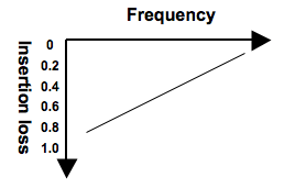
Insertion loss corresponds to the contact resistance of regular relays.
With high-frequency waves, signal loss occurs between contacts when the contacts are closed.
The extent of this signal loss is called insertion loss, and it is expressed in decibels(dB) as the ratio of the output power " Pout " to the input power " Pin ".
The lower the value for the insertion loss obtained by the following formula, the lower the better the characteristics.
The higher the frequency, the greater the loss, and the higher the insertion loss value.

Examples) :
0.1 dB = Approx. 2% signal loss
0.2 dB = Approx. 5% signal loss
1.0 dB = Approx. 20% signal loss

Return loss

In high-frequency circuits, signals do not always flow in one direction. If the impedance (more details later) is mismatched at any point, the signal will be reflected at that point.
Impedance mismatching is easier to under if it is likened to a water pipe.
If the inner diameter of the water pipe (= impedance) changes at a point along the pipe, the water (= signals) will not flow smoothly.
Matching the impedance is an important aspect to consider in high-frequency circuits.
Among the characteristics for regular, there are no characteristics that correspond to reflection.


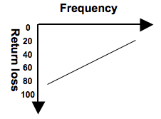
The extent to which signals are reflected is known as return loss, and it is expressed in Decibels(dB) as the ratio of the reflected power " Pref " to the input power " Pin " when the contact is ON.
The higher the value for the return loss obtained the following formula, the lower the reflection and the better the characteristics.
The higher the frequency, the greater the Reflection, and the lower the return loss value.
An increase in the reflection obviously makes it harder for the signals to be transferred Reliably, and so the insertion loss value also increases.

Examples) :
10 dB = 1/10 reflection (10% signal reflection)
20 dB = 1/102 reflection (1% signal reflection)
30 dB = 1/103 reflection (0.1% signal reflection)
60 dB = 1/106 reflection (0.0001% signal reflection)

VSWR

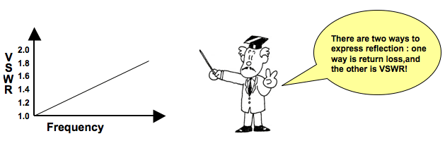
There is another characteristic which expresses the extent of the reflection : VSWR.
The closer the VSWR value is to 1, the lower the reflection and the better the characteristics.
VSWR is short for " voltage standing wave ration ". An increase in the frequency causes an increase in the reflection and an increase in the VSWR value.
The following formula shows the correlation between VSWR and return loss.

Examples) :
When VSWR is 1.1 = the return loss is approx. 26 dB
When VSWR is 1.2 = the return loss is approx. 21 dB
When VSWR is 1.5 = the return loss is approx. 14 dB

Characteristic impedance

In simple terms, impedance can be thought of as resistance. In a high-frequency circuit, it is like having many small resistors Zn aligned in the circuit.
If the resistance is the same for all of these resistors Zn in the circuit, the impedance will match, and there will be no signal reflection.
However, if it differs, reflection arises, making it impossible for the signals to be transferred reliably.
In a high-frequency circuit, the overall impedance of the circuit cannot be calculated by a process of addition as with simple resistors.
This means that when a relay with a characteristic impedance of 50 Ω is used in a 75 Ω type of high-frequency circuit the reflection will be increased.
This impedance is determined by the products in which the circuits are used and, in typical, it is 50 Ω or 75 Ω.

Examples)
50 Ω products : Communications equipment, test and measuring instruments
75 Ω products : TVs, CATV

In the case of relays, it is extremely difficult with today's technology to ensure perfect matching with a 50 Ω or 75 Ω system. Nevertheless, it is necessary to know which relays are closer to 50 Ω and which are closer to 75 Ω.

Microwave Devices Related Information