Safety Light Curtain Type 4 SF4B Ver.2 (Discontinued Products)
Download
-
Discontinued Products
-
Specifications
-
Dimensions
-
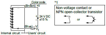
Circuit/ Wiring
-
Cautions For Use
Ⅾiscontinued
Last time buy (JST)
September 30, 2022
Please refer to the details of the discontinued products and the recommended substitutes list below.
------------------------------ Tab1 showing ------------------------------
Discontinued Products

[Note]
The following applicable products and options are available continuously.
Standard components (8-core cable)
Extension cable
| Type | Appearance | Model No. | Description | ||
|---|---|---|---|---|---|
| With connectors on both ends | For emitter |
| SFB-CCJ3E | Length: 3 m 9.843 ft Net weight: 380 g approx. (2 cables) | Used for cable extension or connecting to the SF-C11 and the SF-C14EX control unit. One each for emitter and receiver Connector outer diameter: ø14 mm ø0.551 in max. Connector color: Gray (for emitter), Black (for receiver) Connector outer diameter: ø14 mm ø0.551 in max. |
| SFB-CCJ10E | Length: 10 m 32.808 ft Net weight: 1,200 g approx. (2 cables) | ||||
| For receiver | SFB-CCJ3D | Length: 3 m 9.843 ft Net weight: 190 g approx. (1 cables) | |||
| SFB-CCJ10D | Length: 10 m 32.808 ft Net weight: 1,200 g approx. (2 cables) | ||||
Muting control components (12-core cable, with interference prevention wire)
Extension cable
| Type | Appearance | Model No. | Description | ||
|---|---|---|---|---|---|
| With connector on one end |
| SFB-CC3-MU | Length: 3 m 9.843 ft Net weight: 430 g approx. (2 cables) | Used for connecting to an extension cable or the SF-C13 control unit. 2 cables/set for emitter and receiver Connector outer diameter: ø16 mm ø0.630 in max. | |
| SFB-CC7-MU | Length: 7 m 22.966 ft Net weight: 1,000 g approx. (2 cables) | ||||
| SFB-CC10-MU | Length: 10 m 32.808 ft Net weight: 1,300 g approx. (2 cables) | ||||
| With connectors on both ends | For emitter |
| SFB-CCJ3E-MU | Length: 3 m 9.843 ft Net weight: 190 g approx. (1 cables) | Used for connecting to an extension cable or the SF-C12 control unit. One each for emitter and receiver Connector color: Gray (for emitter), Black (for receiver) Connector outer diameter: ø16 mm ø0.630 in max. |
| SFB-CCJ10E-MU | Length: 10 m 32.808 ft Net weight: 660 g approx. (1 cable) | ||||
| For receiver | SFB-CCJ3D-MU | Length: 3 m 9.843 ft Net weight: 210 g approx. (1 cables) | |||
| SFB-CCJ10D-MU | Length: 10 m 32.808 ft Net weight: 680 g approx. (1 cable) | ||||
| Designation | Model No. | Description |
|---|---|---|
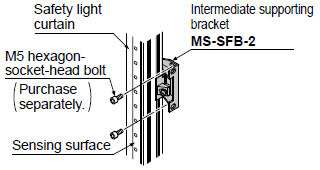
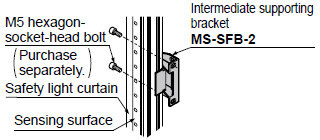
| Intermediate supporting bracket (Note 1) | MS-SFB-2 | Used to mount the safety light curtain in the intermediate position. (2 pcs. per set for emitter and receiver) Mounting is possible behind or at the side of the safety light curtain. |
| Test rod ø14 | SF4B-TR14 | Min. sensing object for regular checking (ø14 mm ø0.551 in), with finger protection type (min. sensing object ø14 mm ø0.551 in) |
| Test rod ø25 | SF4B-TR25 | Min. sensing object for regular checking (ø25 mm ø0.984 in), with hand protection type (min. sensing object ø25 mm ø0.984 in) |
Note : The number of sets required varies depending on the product.
1 set:
SF4B-F□<V2>...... Safety light curtain with 79 to 111 beam channels
SF4B-H□<V2>...... Safety light curtain with 40 to 56 beam channels
SF4B-A□<V2>...... Safety light curtain with 20 to 28 beam channels
2 sets:
SF4B-F127□<V2>
SF4B-H□<V2>...... Safety light curtain with 64 to 80 beam channels
SF4B-A□<V2>...... Safety light curtain with 32 to 40 beam channels
3 sets:
SF4B-H□<V2>....... Safety light curtain with 88 to 96 beam channels
SF4B-A□<V2>....... Safety light curtain with 44 to 48 beam channels
Intermediate supporting bracket
・MS-SFB-2
< In case of rear mounting >
< In case of side mounting >
Control units
| Designation | Appearance | Model No. | Application cable | Description | |
|---|---|---|---|---|---|
| Connector connection type control unit |
| SF-C11 | Bottom cap cable : SFB-CB□ Extension cable : SFB-CCJ□ | Use 8-core cable with connector to connect to the safety light curtain. Compatible with up to Control Category 4. Interference prevention wires and muting function cannot be used. | |
| Slim type control unit |
| SF-C13 | Bottom cap cable : SFB-CCB□(-MU) Extension cable : SFB-CC□(-MU) | Use a discrete wire cable to connect to the safety light curtain. Compatible with up to Control Category 4. Interference prevention wires and muting function can be used. | |
Note : Refer to "Exclusive Control Unit for Safety Light Curtain SF-C10 " for details of the exclusive control units.
Recommended safety relay
SF relay, slim type
SF series
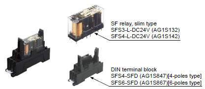
Note:Please contactour sales officefor details on the recommended products.
| Type | With LED indicator | |
|---|---|---|
| Model No. | SFS3-L-DC24V | SFS4-L-DC24V |
| Part No. | AG1S132 | AG1S142 |
| Contact arrangement | 3a1b | 4a2b |
| Rated nominal switching capacity | 6A/250V AC、6A/30V DC | |
| Min. switching capacity | 1mA/5V DC | |
| Coil rating | 15mA/24V DC | 20.8mA/24V DC |
| Rated power consumption | 360mW | 500mW |
| Operation time | 20ms or less | |
| Release time | 20ms or less | |
| Ambient temperature | -40 to +85 ℃ -40 to + 185 ℉ (Humidity: 5 to 85 % RH) | |
| Applicable certifications | UL/c-UL, TÜV, Korea S-mark | |
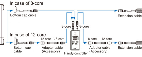
Handy-controller
| Designation | Appearance | Model No. |
|---|---|---|
| Handy-controller |
* Includes 2 adapter cables | SFB-HC |
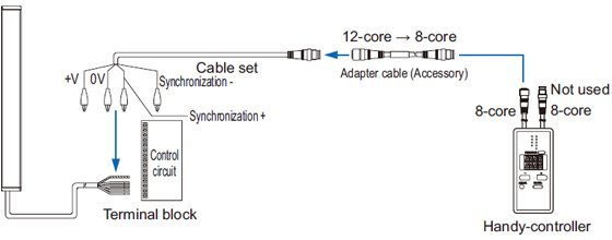
| Cable set for cable type connection |
| SFC-WNC1 |
Note : A handy-controller cannot be used with the SF4B-□-01<V2> and the SF-C14EX-01.
Pigtailed type
Cable type
Y-shaped connector
| Type | Appearance | Model No. | Description | |
|---|---|---|---|---|
| Wire-saving Y-shaped connector |
| SFB-WY1 (Note) | Wire-saving connector for standard components (8-core cable). Cables of emitter and receiver are consolidated into one cable for wire-saving. Wiring has +24 V, 0 V, OSSD 1, OSSD 2, output polarity setting wire (shield). Net weight: 35 g approx. [Power wire and synchronization wire are connected inside the connector. Interlock is disabled (automatic reset).] | |
| Cable with connector on one side |
| WY1-CCN3 (Note) | Cable length: 3 m 9.843 ft Net weight: 200 g approx. (1 cable) | Mating cable for Y-shaped connector Cable color: Gray (with black line) Connector color: Black The min. bending radius: R6 mm R0.236 in |
| WY1-CCN10 (Note) | Cable length: 10 m 32.808 ft Net weight: 620 g approx. (1 cable) | |||
Note : Not compatible with SF4B-□-01<V2>.
By using the Y-shaped connector, the least required wires such as power or safety output are consolidated into one cable. Man-hours taken for wiring is eliminated to the minimum. Construction times as well as wiring mistakes are greatly reduced.

Refer to the instruction manual for more details such as installation of Y-shaped connector, terminal wiring, and wiring example.
Corner mirror
| Designation | Corner mirror | |||
|---|---|---|---|---|
| Applicable beam channels | Model No. | Effective refl ective surface | ||
| Finger | Hand | Arm / Foot | ||
| 23 | 12 | 6 | RF-SFBH-12 | 236 x 72mm 9.291 x 2.835 in |
| 31 | 16 | 8 | RF-SFBH-16 | 316 x 72mm 12.441 x 2.835 in |
| 39 | 20 | 10 | RF-SFBH-20 | 396 x 72mm 15.591 x 2.835 in |
| 47 | 24 | 12 | RF-SFBH-24 | 476 x 72mm 18.740 x 2.835 in |
| 55 | 28 | 14 | RF-SFBH-28 | 556 x 72mm 21.890 x 2.835 in |
| 63 | 32 | 16 | RF-SFBH-32 | 636 x 72mm 25.039 x 2.835 in |
| 71 | 36 | 18 | RF-SFBH-36 | 716 x 72mm 28.189 x 2.835 in |
| 79 | 40 | 20 | RF-SFBH-40 | 796 x 72mm 31.339 x 2.835 in |
| 95 | 48 | 24 | RF-SFBH-48 | 956 x 72mm 37.638 x 2.835 in |
| 111 | 56 | 28 | RF-SFBH-56 | 1,116 x 72mm 43.937 x 2.835 in |
| 127 | 64 | 32 | RF-SFBH-64 | 1,276 x 72mm 50.236 x 2.835 in |
| - | 72 | 36 | RF-SFBH-72 | 1,436 x 72mm 56.535 x 2.835 in |
| - | 80 | 40 | RF-SFBH-80 | 1,596 x 72mm 62.835 x 2.835 in |
| - | 88 | 44 | RF-SFBH-88 | 1,756 x 72mm 69.134 x 2.835 in |
| - | 96 | 48 | RF-SFBH-96 | 1,916 x 72mm 75.433 x 2.835 in |
RF-SFBH-□
Normally for an L-shaped or U-shaped installation, 2 or 3 sets of safety light curtains are needed. With the use of a corner mirror reflecting the light, one set of safety light curtain is possible for L-shaped or U-shaped installation.

Operating range
| With 1 mirror | Declined to 90 % |
|---|---|
| With 2 mirrors | Declined to 80 % |
Others
| Designation | Model No. | Description |
|---|---|---|
| Large display unit for safety light curtain | SF-IND-2 | With the auxiliary output of the safety light curtain, the operation is easily observable from various directions. Specifi cations ・Supply voltage: 24 V DC ±15 % ・Current consumption: 12 mA or less ・Indicators: Orange LED (8 pcs. used)[Light up when external contact is ON] ・Ambient temperature: –10 to +55 ℃ +14 to +131℉(No dew condensation or icing allowed) ・Material: POM (Enclosure), Polycarbonate (Cover), Cold rolled carbon steel (SPCC) (Bracket) ・Cable: 0.3mm2 2-core cabtyre cable, 3m 9.843 ft long ・Weight: 70 g approx. (including bracket) I/O circuit diagrams <With NPN output type>
<With PNP output type>
|
------------------------------ Tab2 showing ------------------------------
Specifications
Safety light curtain individual specifications
SF4B-F□(-01)<V2>
| Type | Min. sensing object ø14 mm ø0.551 in type (10 mm 0.394 in beam pitch) | ||||||
|---|---|---|---|---|---|---|---|
| Model No. | SF4B-F23 (-01) <V2> | SF4B-F31 (-01) <V2> | SF4B-F39 (-01) <V2> | SF4B-F47 (-01) <V2> | SF4B-F55 (-01) <V2> | SF4B-F63 (-01) <V2> | |
| Number of beam channels | 23 | 31 | 39 | 47 | 55 | 63 | |
| Protective height(Note 2) | 230 mm 9.055 in | 310 mm 12.205 in | 390 mm 15.354 in | 470 mm 18.504 in | 550 mm 21.654 in | 630 mm 24.803 in | |
| China Press compliant (GB/T 4584) | 220 mm 8.661 in | 300 mm 11.811 in | 380 mm 14.960 in | 460 mm 18.110 in | 540 mm 21.260 in | 620 mm 24.409 in | |
| Current consumption | Emitter: 80 mA or less, Receiver: 120 mA or less | Emitter: 100 mA or less, Receiver: 160 mA or less | |||||
| PFHD | 2.4 × 10⁻⁹ | 2.8 × 10⁻⁹ | 3.2 × 10⁻⁹ | 3.6 × 10⁻⁹ | 4.0 × 10⁻⁹ | 4.4 × 10⁻⁹ | |
| MTTFD | 100 years or more | ||||||
| Net weight (Total of emitter and receiver) | 510 g approx. | 660 g approx. | 810 g approx. | 960 g approx. | 1,110 g approx. | 1,260 g approx. | |
| Type | Min. sensing object ø14 mm ø0.551 in type (10 mm 0.394 in beam pitch) | |||||
|---|---|---|---|---|---|---|
| Model No. | SF4B-F71 (-01) <V2> | SF4B-F79 (-01) <V2> | SF4B-F95 (-01) <V2> | SF4B-F111 (-01) <V2> | SF4B-F127 (-01) <V2> | |
| Number of beam channels | 71 | 79 | 95 | 111 | 127 | |
| Protective height(Note 2) | 710 mm 27.953 in | 790 mm 31.102 in | 950 mm 37.402 in | 1,110 mm 43.701 in | 1,270 mm 50.000 in | |
| China Press compliant (GB/T 4584) | 700 mm 27.559 in | 780 mm 30.708 in | 940 mm 37.007 in | 1,100 mm 43.306 in | 1,260 mm 49.606 in | |
| Current consumption | Emitter: 100 mA or less, Receiver: 160 mA or less | Emitter: 115 mA or less, Receiver: 190 mA or less | Emitter: 135 mA or less, Receiver: 230 mA or less | |||
| PFHD | 4.8 × 10⁻⁹ | 5.2 × 10⁻⁹ | 6.0 × 10⁻⁹ | 6.8 × 10⁻⁹ | 7.6 × 10⁻⁹ | |
| MTTFD | 100 years or more | |||||
| Net weight (Total of emitter and receiver) | 1,420 g approx. | 1,570 g approx. | 1,870 g approx. | 2,170 g approx. | 2,470 g approx. | |
Notes:
1) Where measurement conditions have not been specified precisely, the conditions used were an ambient temperature of +20 ℃ +68 ℉. The model No.
with "G" is a robust type.
PFHD: Probability of dangerous failure per hour, MTTFD: Mean time to dangerous failure (in years)
2) In the case of "When used as safety device for presses in China", the distance between the center of the first beam axis and the center of the last beam axis of the device becomes the protective height.
SF4B-H□(-01)<V2>
| Type | Min. sensing object ø25 mm ø0.984 in type (20 mm 0.787 in beam pitch) | ||||||
|---|---|---|---|---|---|---|---|
| Model No. | SF4B-H12 (-01) <V2> | SF4B-H16 (-01) <V2> | SF4B-H20 (-01) <V2> | SF4B-H24 (-01) <V2> | SF4B-H28 (-01) <V2> | ||
| Number of beam channels | 12 | 16 | 20 | 24 | 28 | ||
| Protective height(Note 2) | 230 mm 9.055 in | 310 mm 12.205 in | 390 mm 15.354 in | 470 mm 18.504 in | 550 mm 21.654 in | ||
| China Press compliant (GB/T 4584) | 220 mm 8.661 in | 300 mm 11.811 in | 380 mm 14.960 in | 460 mm 18.110 in | 540 mm 21.260 in | ||
| Current consumption | Emitter: 70 mA or less, Receiver: 95 mA or less | Emitter: 80 mA or less, Receiver: 115 mA or less | |||||
| PFHD | 1.8 × 10⁻⁹ | 2.0 × 10⁻⁹ | 2.2 × 10⁻⁹ | 2.4 × 10⁻⁹ | 2.6 × 10⁻⁹ | ||
| MTTFD | 100 years or more | ||||||
| Net weight (Total of emitter and receiver) | 510 g approx. | 660 g approx. | 810 g approx. | 960 g approx. | 1,110 g approx. | ||
| Type | Min. sensing object ø25 mm ø0.984 in type (20 mm 0.787 in beam pitch) | ||||||
|---|---|---|---|---|---|---|---|
| Model No. | SF4B-H32 (-01) <V2> | SF4B-H36 (-01) <V2> | SF4B-H40 (-01) <V2> | SF4B-H48 (-01) <V2> | SF4B-H56 (-01) <V2> | ||
| Number of beam channels | 32 | 36 | 40 | 48 | 56 | ||
| Protective height(Note 2) | 630 mm 24.803 in | 710 mm 27.953 in | 790 mm 31.102 in | 950 mm 37.402 in | 1,110 mm 43.701 in | ||
| China Press compliant (GB/T 4584) | 620 mm 24.409 in | 700 mm 27.559 in | 780 mm 30.708 in | 940 mm 37.007 in | 1,100 mm 43.306 in | ||
| Current consumption | Emitter: 80 mA or less, Receiver: 115 mA or less | Emitter: 90 mA or less, Receiver: 140 mA or less | Emitter: 100 mA or less, Receiver: 160 mA or less | ||||
| PFHD | 2.8 × 10⁻⁹ | 3.0 × 10⁻⁹ | 3.2 × 10⁻⁹ | 3.6 × 10⁻⁹ | 4.0 × 10⁻⁹ | ||
| MTTFD | 100 years or more | ||||||
| Net weight (Total of emitter and receiver) | 1,260 g approx. | 1,420 g approx. | 1,570 g approx. | 1,870 g approx. | 2,170 g approx. | ||
| Type | Min. sensing object ø25 mm ø0.984 in type (20 mm 0.787 in beam pitch) | |||||
|---|---|---|---|---|---|---|
| Model No. | SF4B-H64 (-01) <V2> | SF4B-H72 (-01) <V2> | SF4B-H80 (-01) <V2> | SF4B-H88 (-01) <V2> | SF4B-H96 (-01) <V2> | |
| Number of beam channels | 64 | 72 | 80 | 88 | 96 | |
| Protective height(Note 2) | 1,270 mm 50.000 in | 1,430 mm 56.299 in | 1,590 mm 62.598 in | 1,750 mm 68.898 in | 1,910 mm 75.197 in | |
| China Press compliant (GB/T 4584) | 1,260 mm 49.606 in | 1,420 mm 55.905 in | 1,580 mm 62.205 in | 1,740 mm 68.503 in | 1,900 mm 74.803 in | |
| Current consumption | Emitter: 100 mA or less, Receiver: 160 mA or less | Emitter: 110 mA or less, Receiver: 180 mA or less | Emitter: 120 mA or less, Receiver: 200 mA or less | |||
| PFHD | 4.4 × 10⁻⁹ | 4.8 × 10⁻⁹ | 5.2 × 10⁻⁹ | 5.6 × 10⁻⁹ | 6.0 × 10⁻⁹ | |
| MTTFD | 100 years or more | |||||
| Net weight (Total of emitter and receiver) | 2,470 g approx. | 2,770 g approx. | 3,070 g approx. | 3,370 g approx. | 3,670 g approx. | |
Notes:
1) Where measurement conditions have not been specified precisely, the conditions used were an ambient temperature of +20 ℃ +68 ℉. The model No.
with "G" is a robust type.
PFHD: Probability of dangerous failure per hour, MTTFD: Mean time to dangerous failure (in years)
2) In the case of "When used as safety device for presses in China", the distance between the center of the first beam axis and the center of the last beam axis of the device becomes the protective height.
SF4B-A□(-01)<V2>
| Type | Min. sensing object ø45 mm ø1.772 in type (40 mm 1.575 in beam pitch) | |||||
|---|---|---|---|---|---|---|
| Model No. | SF4B-A6 (-01) <V2> | SF4B-A8 (-01) <V2> | SF4B-A10 (-01) <V2> | SF4B-A12 (-01) <V2> | SF4B-A14 (-01) <V2> | |
| Number of beam channels | 6 | 8 | 10 | 12 | 14 | |
| Protective height(Note 2) | 230 mm 9.055 in | 310 mm 12.205 in | 390 mm 15.354 in | 470 mm 18.504 in | 550 mm 21.654 in | |
| China Press compliant (GB/T 4584) | 200 mm 7.874 in | 280 mm 11.024 in | 360 mm 14.173in | 440 mm 17.323 in | 520 mm 20.472 in | |
| Current consumption | Emitter: 65 mA or less, Receiver: 85 mA or less | Emitter: 70 mA or less, Receiver: 95 mA or less | ||||
| PFHD | 1.5 × 10⁻⁹ | 1.6 × 10⁻⁹ | 1.7 × 10⁻⁹ | 1.8 × 10⁻⁹ | 1.9 × 10⁻⁹ | |
| MTTFD | 100 years or more | |||||
| Net weight (Total of emitter and receiver) | 510 g approx. | 660 g approx. | 810 g approx. | 960 g approx. | 1,110 g approx. | |
| Type | Min. sensing object ø45 mm ø1.772 in type (40 mm 1.575 in beam pitch) | |||||
|---|---|---|---|---|---|---|
| Model No. | SF4B-A16 (-01) <V2> | SF4B-A18 (-01) <V2> | SF4B-A20 (-01) <V2> | SF4B-A24 (-01) <V2> | SF4B-A28 (-01) <V2> | |
| Number of beam channels | 16 | 18 | 20 | 24 | 28 | |
| Protective height(Note 2) | 630 mm 24.803 in | 710 mm 27.953 in | 790 mm 31.102 in | 950 mm 37.402 in | 1,110 mm 43.701 in | |
| China Press compliant (GB/T 4584) | 600 mm 23.622 in | 680 mm 26.772 in | 760 mm 29.921 in | 920 mm 36.220 in | 1,080 mm 42.520 in | |
| Current consumption | Emitter: 70 mA or less, Receiver: 95 mA or less | Emitter: 75 mA or less, Receiver: 105 mA or less | Emitter: 80 mA or less, Receiver: 120 mA or less | |||
| PFHD | 2.0 × 10⁻⁹ | 2.1 × 10⁻⁹ | 2.2 × 10⁻⁹ | 2.4 × 10⁻⁹ | 2.6 × 10⁻⁹ | |
| MTTFD | 100 years or more | |||||
| Net weight (Total of emitter and receiver) | 1,260 g approx. | 1,420 g approx. | 1,570 g approx. | 1,870 g approx. | 2,170 g approx. | |
| Type | Min. sensing object ø45 mm ø1.772 in type (40 mm 1.575 in beam pitch) | |||||
|---|---|---|---|---|---|---|
| Model No. | SF4B-A32 (-01) <V2> | SF4B-A36 (-01) <V2> | SF4B-A40 (-01) <V2> | SF4B-A44 (-01) <V2> | SF4B-A48 (-01) <V2> | |
| Number of beam channels | 32 | 36 | 40 | 44 | 48 | |
| Protective height(Note 2) | 1,270 mm 50.000 in | 1,430 mm 56.299 in | 1,590 mm 62.598 in | 1,750 mm 68.898 in | 1,910 mm 75.197 in | |
| China Press compliant (GB/T 4584) | 1,240 mm 48.819 in | 1,400 mm 55.118 in | 1,560 mm 61.417 in | 1,720 mm 67.716 in | 1,880 mm 74.016 in | |
| Current consumption | Emitter: 80 mA or less, Receiver: 120 mA or less | Emitter: 85 mA or less, Receiver: 130 mA or less | Emitter: 95 mA or less, Receiver: 140 mA or less | |||
| PFHD | 2.8 × 10⁻⁹ | 3.0 × 10⁻⁹ | 3.2 × 10⁻⁹ | 3.4 × 10⁻⁹ | 3.6 × 10⁻⁹ | |
| MTTFD | 100 years or more | |||||
| Net weight (Total of emitter and receiver) | 2,470 g approx. | 2,770 g approx. | 3,070 g approx. | 3,370 g approx. | 3,670 g approx. | |
Notes:
1) Where measurement conditions have not been specified precisely, the conditions used were an ambient temperature of +20 ℃ +68 ℉. The model No.
with "G" is a robust type.
PFHD: Probability of dangerous failure per hour, MTTFD: Mean time to dangerous failure (in years)
2) In the case of "When used as safety device for presses in China", the distance between the center of the first beam axis and the center of the last beam axis of the device becomes the protective height.
Safety light curtain common specifications
| Type | Min. sensing object ø14 mm ø0.551 in type | Min. sensing object ø25 mm ø0.984 in type | Min. sensing object ø45 mm ø1.772 in type | |
|---|---|---|---|---|
| Model No. | SF4B-F□(-01)<V2> | SF4B-H□(-01)<V2> | SF4B-A□(-01)<V2> | |
| Applicable standards (Note 2) | International standard | IEC 61496-1/2 (Type 4), ISO 13849-1 (Category 4, PLe), IEC 61508-1 to 7 (SIL3) | ||
| Japan | JIS B 9704-1/2 (Type 4), JIS B 9705-1 (Category 4), JIS C 0508-1 to 7 (SIL3) | |||
| Europe (EU) | EN 61496-1 (Type 4), EN ISO 13849-1 (Category 4, PLe), EN 61508-1 to 7 (SIL3), EN 55011, EN 50178, EN 61000-6-2 | |||
| North America | ANSI/UL 61496-1/2 (Type 4), ANSI/UL 508, UL 1998 (Class 2), CAN/CSA 61496-1/2 (Type 4), CAN/CSA C22.2 No.14, OSHA 1910.212, OSHA 1910.217(C), ANSI B11.1 to B11.19, ANSI/RIA 15.06 | |||
| South Korea (S-Mark) | S1-G-35-2005, S2-W-11-2003 (SF4B-□<V2> only) | |||
| China (GB) | GB/T 4584 | |||
| CE marking directive compliance | Machinery Directive, EMC Directive, RoHS Directive | |||
| Operating range (Note 3) | 0.3 to 7 m 0.984 to 22.966 ft | 12 to 64 beam channels type: 0.3 to 9 m 0.984 to 29.528 ft 72 to 96 beam channels type: 0.3 to 7 m 0.984 to 22.966 ft | 6 to 32 beam channels type: 0.3 to 9 m 0.984 to 29.528 ft 36 to 48 beam channels type: 0.3 to 7 m 0.984 to 22.966 ft | |
| Min. sensing object (Note 4) | ø14 mm ø0.551 in opaque object | ø25 mm ø0.984 in opaque object | ø45 mm ø1.772 in opaque object | |
| Effective aperture angle | ±2.5° or less [for an operating range exceeding 3 m 9.843 ft (conforming to IEC 61496-2 / ANSI/UL 61496-2)] | |||
| Supply voltage | 24 V DC ± 10 % Ripple P-P 10 % or less | |||
| Control outputs (OSSD 1, OSSD 2) | PNP open-collector transistor / NPN open-collector transistor (switching method) ・When selecting PNP output: Max. source current 200 mA, When selecting NPN output: Max. sink current 200 mA ・Applied voltage: same as supply voltage (When selecting PNP output: between the control output and +V, When selecting NPN output: between the control output and 0 V) ・Residual voltage: 2.5V or less (When selecting PNP output: source current 200 mA, when selecting NPN output: sink current 200 mA) (when using 20 m 65.617 ft length cable) | |||
| Operation mode | ON when all beam channels are received, OFF when one or more beam channels are interrupted (OFF also in case of any malfunction in the safety light curtain or the synchronization signal) (Note 5,6) | |||
| Protection circuit | Incorporated | |||
| Response time | OFF response: 14 ms or less, ON response: 80 to 90 ms | |||
| Auxiliary output (Non-safety output) | PNP open-collector transistor / NPN open-collector transistor (switching method) ・When selecting PNP output: Max. source current 60 mA, When selecting NPN output: Max. sink current 60 mA ・Applied voltage: same as supply voltage (When selecting PNP output: between the auxiliary output and +V, When selecting NPN output: between the auxiliary output and 0 V) ・Residual voltage: 2.5V or less (When selecting PNP output: source current 60 mA, when selecting NPN output: sink current 60 mA) (when using 20 m 65.617 ft length cable) | |||
| Operation mode | OFF when control outputs are ON, ON when control outputs are OFF (Factory setting; operating mode can be changed using the SFB-HC handy-controller). | |||
| Protection circuit | Incorporated | |||
| Responce time | OFF replay: 34 ms or less, ON replay 110 ms or less | |||
| Interference prevention function | Incorporated (Note 7) | |||
| Emission halt function / Interlock function | Incorporated / Incorporated [Manual reset / Auto reset (Note 8)] | |||
| External device monitoring function | Incorporated | |||
| Override function / Muting function | Incorporated (Note 7) / Incorporated (Note 7) | |||
| Optional functions (Note 9) | Fixed blanking, floating blanking, auxiliary output switching, interlock setting changing, external relay monitor setting changing, muting setting changing, protecting, light emitting amount control | |||
| Degree of protection | IP67 / IP65 (IEC) | |||
| Ambient temperature | -10 to +55 ℃ +14 to +131 ℉ (No dew condensation or icing allowed), Storage: -25 to +70 ℃ -13 to +158 ℉ | |||
| Ambient humidity | 30 to 85 % RH, Storage: 30 to 95 % RH | |||
| Ambient illuminance | Incandescent light: 3,500 lx or less at the light-receiving face | |||
| Dielectric strength voltage | 1,000 V AC for one min. between all supply terminals connected together and enclosure | |||
| Insulation resistance | 20 MΩ, or more, with 500 V DC megger between all supply terminals connected together and enclosure | |||
| Vibration resistance | 10 to 55 Hz frequency, 0.75 mm 0.030 in double amplitude in X, Y and Z directions for two hours each | |||
| Shock resistance | 300 m/s2 acceleration (30 G approx.) in X, Y and Z directions three times each | |||
| Emitting element | Infrared LED (Peak emission wavelength: 870 nm 0.034 mil) | |||
| Material | Enclosure: Aluminium, Upper and lower edges: Iron, Sensing surface: Polycarbonate and Polyester resin, Cap: PBT | |||
| Connecting method / Cable length | Connector / Total length up to 50 m 164.042 ft is possible for both emitter and receiver, with optional mating cables (Note 10) | |||
| Accessories | MS-SFB-2 (Intermediate supporting bracket): (Note 11) SF4B-TR14 (Test rod): 1 No | MS-SFB-2 (Intermediate supporting bracket): (Note 11) SF4B-TR25 (Test rod): 1 No | MS-SFB-2 (Intermediate supporting bracket): (Note 11) | |
Notes:
1) Where measurement conditions have not been specified precisely, the conditions used were an ambient temperature of +20 ℃ +68 ℉.
2) PLe SIL3 compliant from production in August 2009.
3) The operating range is the possible setting distance between the emitter and the receiver.
4) When the floating blanking function is used, the size of the min. sensing object is changed.
5) The outputs are not "OFF" when muting function is active even if the beam channel is interruped.
6) In case the blanking function is valid, the operation mode is changed.
7) Please use 12-core cable.
8) The manual reset and auto reset are possible to be switched depending on the wiring status.
9) In case of using optional function, the handy-controller (SFB-HC) (optional) is required. However, a handy-controller cannot be used with the SF4B-□-01<V2>,SF4B-□-03<V2> and the SF-C14EX-01.
10) The cable can be extended within 30 m 98.425 ft (for emitter / receiver) when two safety light curtains are connected in series, within 20 m 65.617 ft when three safety light curtains are connected in series. Furthermore, when the muting lamp is used, the cable can be extended within 40 m 131.234 ft (for emitter / receiver).
11) The intermediate supporting bracket (MS-SFB-2) is enclosed with the following models. The number of sets required varies depending on the product.
[1 set]
SF4B-F□<V2>...79 to 111 beam channels
SF4B-H□<V2>...40 to 56 beam channels
SF4B-A□<V2>...20 to 28 beam channels
[2 sets]
SF4B-F127<V2>, SF4B-H□<V2>...64 to 80 beam channels
SF4B-A□<V2>...32 to 40 beam channels
[3 sets]
SF4B-H□<V2>...88 to 96 beam channels
SF4B-A□<V2>...44 to 48 beam channels
Handy-controller
| Model No. | SFB-HC |
|---|---|
| Supply voltage | 24 V DC ± 10 % Ripple P-P10 % or less (common to safety light curtain power supply) |
| Current consumption | 65 mA or less |
| Communication method | RS-485 two-way communications (Specific procedure) |
| Digital display | 4-digit red LED display x 2 (Selected beam channels, setting contents etc. are displayed.) |
| Function indicator | Green LED x 9 (set function is displayed.) |
| Functions | Fixed blanking (Factory setting: Disabled) / Floating blanking (Factory setting: Disabled) / Auxiliary output change (Factory setting: Negative Logic of OSSD) / Light emitting amount control (Factory setting: Disabled) / Muting setting change [Factory setting: All beam channels enabled, A = B, Setting of the muting lamp diagnosis function enabled (Ver. 2 or later), Muting sensor output operation setting N.O. / N.C. (Ver. 2.1 or later)] Interlock setting change (Factory setting: start / restart) / External device monitoring setting change (Factory setting: Enabled, 300 ms) / Override setting changing function 60 sec. (Ver. 2.1 or later) / Setting detail monitoring / Protecting (Factory setting: Disabled) (Factory password setting: 0000) / Initialization / Copy |
| Ambient temperature | -10 to +55 ℃ +14 to +131 ℉ (No dew condensation or icing allowed), Storage: -25 to +70 ℃ -13 to +158 ℉ |
| Ambient humidity | 30 to 85 % RH, Storage: 30 to 85 % RH |
| Voltage withstandability | 1,000 V AC for one min. between all supply terminals connected together and enclosure |
| Insulation resistance | 20 MΩ , or more, with 500 V DC megger between all supply terminals connected together and enclosure |
| Cable | 8-core shielded cable, 0.5 m 1.640 ft long, with a connector at the end (2 cables) |
| Material | Enclosure: ABS |
| Weight | Net weight: 200 g approx. |
| Accessories | Adapter cable: 2 cables |
Note:Where measurement conditions have not been specified precisely, the conditions used were an ambient temperature of +20 ℃ +68 ℉.
Laser alignment tool
| Model No. | SF-LAT-2N |
|---|---|
| Supply voltage | 3 V (LR6 battery x 2 pcs.) |
| Battery | 1.5 V (LR6 battery) x 2 pcs. (replaceable)(Note 2) |
| Battery lifetime | 30 hours approx. of continuous operation (LR6 battery, at +25 ℃ +77 ℉ ambient temperature) |
| Light source | Red semiconductor laser: class 2 (IEC / JIS), Class II (FDA) (Max. output: 1 mW, Peak emission wavelength: 650 nm 0.026 mil)(Note 3) |
| Spot diameter | 10 mm 0.394 in approx. (at 5 m 16.404 ft distance) |
| Ambient temperature | 0 to +40 ℃ +32 to +104 ℉ (No dew condensation), Storage: 0 to +55 ℃ +32 to +131 ℉ |
| Ambient humidity | 35 to 85 % RH, Storage: 35 to 85 % RH |
| Material | Enclosure: ABS, Mounting part: Aluminum |
| Weight | Net weight: 150 g approx. (without batteries) |
Notes:
1) Where measurement conditions have not been specified precisely, the conditions used were an ambient temperature of +20 ℃ +68 ℉.
2) LR6 dry cell batteries are not provided with the product. Please purchase them separately.
3) This product complies with the FDA regulations (FDA 21 CFR 1040.10 and 1040.11) in accordance with FDA Laser Notice No. 56, except for complying with IEC 60825-1 Ed. 3.
Corner mirror
| Model No. | RF-SFBH-□ |
|---|---|
| Attenuation rate of sensing range | With one corner mirror: Declined to 90 %, With two corner mirrors: Declined to 80 % (When used in combination with the SF4B series) |
| Ambient temperature | -10 to +55 ℃ +14 to +131 ℉ (No dew condensation or icing allowed), Storage: -25 to +70 ℃ -13 to +158 ℉ |
| Ambient humidity | 30 to 85 % RH, Storage: 30 to 95 % RH |
| Vibration resistance | 10 to 55 Hz frequency, 0.75 mm 0.030 in double amplitude in X, Y and Z directions for two hours each |
| Shock resistance | 300 m/s2 acceleration (30 G approx.) in X, Y and Z directions three times each |
| Material | Enclosure: Aluminum, Mounting bracket: Stainless steel, Mirror (rear surface mirror): Glass, Side cover: EPDM |
| Accessories | Intermediate supporting bracket: 1 set (RF-SFBH-40/48/56/64), 2 sets (RF-SFBH-72/80/88/96) |
Note:Where measurement conditions have not been specified precisely, the conditions used were an ambient temperature of +20 ℃ +68 ℉.
------------------------------ Tab3 showing ------------------------------
Dimensions
- Unit: mm in
SF4B-□<V2>
Safety light curtain
Assembly dimensions
Mounting drawing for the safety light curtains using the standard mounting brackets MS-SFB-1 (optional) and the intermediate supporting brackets.
<Rear mounting>

<Side mounting>

| Model No. | Protective height (Main body length) | Mount- ing pitch | Total length | Intermediate supporting bracket mounting pitch | ||||||
|---|---|---|---|---|---|---|---|---|---|---|
| A | A' (Note 1) | B | C | D | E | F | ||||
| SF4B-F□-01<V2> SF4B-H□-01<V2> | SF4B-A□-01<V2> | |||||||||
| SF4B-F23□ <V2> | SF4B-H12□ <V2> | SF4B-A6□ <V2> | 230 9.055 | 220 8.661 | 200 7.874 | 270 10.630 | 286 11.260 | - | - | - |
| SF4B-F31□ <V2> | SF4B-H16□ <V2> | SF4B-A8□ <V2> | 310 12.205 | 300 11.811 | 280 11.024 | 350 13.780 | 366 14.406 | - | - | - |
| SF4B-F39□ <V2> | SF4B-H20□ <V2> | SF4B-A10□ <V2> | 390 15.354 | 380 14.960 | 360 14.173 | 430 16.929 | 446 17.559 | - | - | - |
| SF4B-F47□ <V2> | SF4B-H24□ <V2> | SF4B-A12□ <V2> | 470 18.504 | 460 18.110 | 440 17.323 | 510 20.079 | 526 20.709 | - | - | - |
| SF4B-F55□ <V2> | SF4B-H28□ <V2> | SF4B-A14□ <V2> | 550 21.654 | 540 21.260 | 520 20.472 | 590 23.228 | 606 23.858 | - | - | - |
| SF4B-F63□ <V2> | SF4B-H32□ <V2> | SF4B-A16□ <V2> | 630 24.803 | 620 24.409 | 600 23.622 | 670 26.378 | 686 27.008 | - | - | - |
| SF4B-F71□ <V2> | SF4B-H36□ <V2> | SF4B-A18□ <V2> | 710 27.953 | 700 27.559 | 680 26.772 | 750 29.528 | 766 30.157 | - | - | - |
| SF4B-F79□ <V2> | SF4B-H40□ <V2> | SF4B-A20□ <V2> | 790 31.102 | 780 30.708 | 760 29.921 | 830 32.677 | 846 33.307 | 390 15.354 | - | - |
| SF4B-F95□ <V2> | SF4B-H48□ <V2> | SF4B-A24□ <V2> | 950 37.402 | 940 37.007 | 920 36.220 | 990 38.976 | 1,006 39.606 | 470 18.504 | - | - |
| SF4B-F111□ <V2> | SF4B-H56□ <V2> | SF4B-A28□ <V2> | 1,110 43.701 | 1,100 43.701 | 1,080 42.520 | 1,150 45.276 | 1,166 45.905 | 550 21.654 | - | - |
| SF4B-F127□ <V2> | SF4B-H64□ <V2> | SF4B-A32□ <V2> | 1,270 50.000 | 1,260 49.606 | 1,240 48.819 | 1,310 51.575 | 1,326 52.505 | 418 16.457 | 842 33.150 | - |
| - | SF4B-H72□ <V2> | SF4B-A36□ <V2> | 1,430 56.299 | 1,420 55.905 | 1,400 55.118 | 1,470 57.874 | 1,486 58.504 | 472 18.583 | 948 37.323 | - |
| - | SF4B-H80□ <V2> | SF4B-A40□ <V2> | 1,590 62.598 | 1,580 62.205 | 1,560 61.417 | 1,630 64.173 | 1,646 64.803 | 525 20.669 | 1,055 41.535 | - |
| - | SF4B-H88□ <V2> | SF4B-A44□ <V2> | 1,750 68.898 | 1,740 68.504 | 1,720 67.716 | 1,790 70.472 | 1,806 71.102 | 433 17.047 | 870 34.252 | 1,380 51.496 |
| - | SF4B-H96□ <V2> | SF4B-A48□ <V2> | 1,910 75.197 | 1,900 74.803 | 1,880 74.016 | 1,950 76.772 | 1,966 77.401 | 473 18.622 | 950 37.402 | 1,428 56.220 |
Note 1: When SF4B-□-01<v2> is used for China press machine as a safety device, the distance between the center of the 1st beam axis and the center of the last beam axis is regarded as protective height A’.
| Model No. | Beam pitch | First beam channel position |
|---|---|---|
| G | H | |
| SF4B-F□<V2> | 10 0.394 | 5 0.197 |
| SF4B-H□<V2> | 20 0.787 | 5 0.197 |
| SF4B-A□<V2> | 40 1.575 | 15 0.591 |
SF4B-□<V2>
Safety light curtain
Assembly dimensions
Mounting drawing for the safety light curtain on which the dead zoneless brackets MS-SFB-3 (optional) and the intermediate supporting brackets are mounted.
<Rear mounting]

<Side mounting>


SF4B-□<V2>
Protection bar set MC-SFBH-□ assembly dimensions

Material:Mounting bracket … Die-cast zinc alloyProtection bar … AluminumTwo brackets (one pc. each of R type and L type), one protection bar[Two pcs. each of M5 (length 16 mm0.630 in)hexagon-socket-head bolts, M5 (length 20 mm0.787 in)hexagon-socket-head bolt are attached.]
Protection bar set for rear / side mounting MC-SFBH-□-T assembly dimensions
[Rear mounting]

<Side mounting>

Material:
Mounting bracket … Iron (Trivalent chrome plated)
Protection bar … AluminumTwo brackets (one pc. each of R type and L type), one protection bar
[Two pcs. each of M5 (length 18 mm 0.709 in)hexagon-socket-head bolts, M5 (length 20 mm 0.787 in)hexagon-socket-head bolt are attached.]

RF-SFBH-□
Corner mirror (Optional)


MS-SFB-1
Standard mounting bracket (Optional)

Material:
Die-cast zinc alloy
Four bracket set[Four M5 (length 18 mm 0.709 in) hexagon-socket-head bolts are attached]
MS-SFB-1-T
M8 Mounting bracket (Optional)

Material:
Die-cast zinc alloy
Four bracket set[Four M5 (length 18 mm 0.709 in) hexagon-socket-head bolts are attached.]
MS-SFB-2
Intermediate supporting bracket (Accessory for safety light curtain)

Material:
Die-cast zinc alloy
Note:The intermediate supporting bracket (MS-SFB-2) is enclosed with the following products. The quantity differs depending on the product as shown below:
1 set:
SF4B-F□<V2> … 79 to 111 beam channels
SF4B-H□<V2> … 40 to 56 beam channels
SF4B-A□<V2> … 20 to 28 beam channels
2 sets:
SF4B-F127<V2>SF4B-H□<V2> … 64 to 80 beam channels
SF4B-A□<V2> … 32 to 40 beam channels
3 sets:
SF4B-H□<V2> … 88 to 96 beam channels
SF4B-A□<V2> … 44 to 48 beam channels
MS-SFB-3
Dead zoneless mounting bracket (Optional)
[Main body]
![MS-SFB-3 [Main body]](https://ap.industry.panasonic.com/hubfs/pid-corp/products/fasys/sensor/safety/sf4b_v2/size_figure/images/pic18.jpg)
Material:
Die-cast zinc alloy
Four bracket set[Four M5 (length 25 mm 0.984 in) hexagon-socket-head bolts and four spacers are attached.]
[L-shaped mounting]
![MS-SFB-3 [L-shaped mounting]](https://ap.industry.panasonic.com/hubfs/pid-corp/products/fasys/sensor/safety/sf4b_v2/size_figure/images/pic19.jpg)
[Mounting adjustment range]
The adjustment range of the safety light curtain angle is up to ±15 degrees

Note:The finger protection type has a beam pitch of 10 mm 0.394 in, which produces a dead zone. Additional measures will be required, such as using a protection cover.
MS-SFB-4
Pitch adapter bracket (Optional)
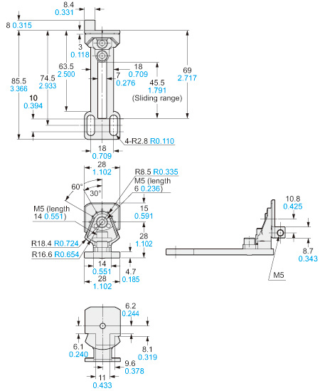
Material:
Die-cast zinc alloy
Four bracket set[Four M5 (length 18 mm 0.709 in) hexagon-socket-head bolts are attached]
MS-SFB-4-T
M8 pitch adapter bracket (Optional)
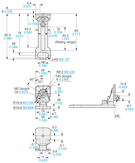
Material:
Die-cast zinc alloy
Four bracket set[Four M5 (length 18 mm 0.709 in) hexagon-socket-head bolts are attached]
MS-SFB-7-T MS-SFB-1-T2 (Rear mounting)
M8 rear mounting bracket (Optional) M8 rear / side mounting brackets set (Optional)
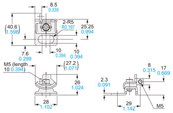
Material:
Iron (Trivalent chrome plated)
Four bracket set[Four M5 (length 18 mm 0.709 in) hexagon-socket-head bolts are attached.]
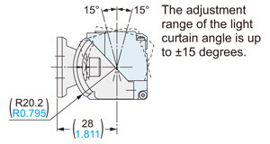
[Mounting adjustment range]

MS-SFB-8-T MS-SFB-1-T2 (Side mounting)
M8 side mounting bracket (Optional) M8 rear / side mounting brackets set (Optional)
[MS-SFB-8-T(R)]

[MS-SFB-8-T(L)]
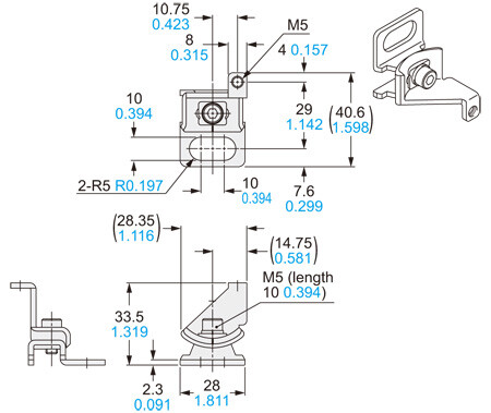
[Mounting adjustment range]
Material:
Iron (Trivalent chrome plated)
Four bracket(two pcs. each of R type and L type) set
[Four M5 (length 18 mm 0.709 in) hexagon-socket-head bolts are attached.]
SFB-WY1
Y-shaped connector (Optional)

Net weight: 35 g approx.
SFB-HC
Handy-controller (Optional)
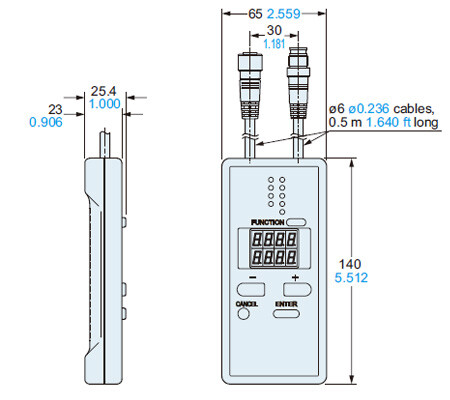
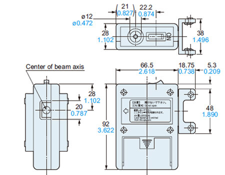
SF-LAT-2N
Laser alignment tool (Optional)
SF-IND-2
Large display unit for safety light curtain (Optional)
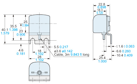
Material:
Bracket: Cold rolled carbon steel (SPCC) (Black chromate)
Enclosure: POM
Cover: Polycarbonate
------------------------------ Tab4 showing ------------------------------
I/O Circuit and Wiring diagrams
I/O circuit diagram
<In case of using I/O circuit for PNP output>

Note: The above diagram is when using a 12-core cable. If an 8-core cable is used, the red, yellow, gray, gray / black, sky-blue / white and sky-blue / black lead wires are absent.
*S1
Switch S1
・Emission halt input / Reset input
For manual reset
Vs to Vs – 2.5 V (sink current 5 mA or less): Emission halt (Note 1)
Open: Emission
For automatic reset
Vs to Vs – 2.5 V (sink current 5 mA or less): Emission (Note 1)
Open: Emission halt
・Interlock setting input, Override input, Muting input A / B,
External device monitoring input
Vs to Vs – 2.5 V (sink current 5 mA or less): Enabled (Note 1)
Open: Disabled
Note: Vs is the applying supply voltage.
<In case of using I/O circuit for NPN output>

Note: The above diagram is when using a 12-core cable. If an 8-core cable is used, the red, yellow, gray, gray / black, sky-blue / white and sky-blue / black lead wires are absent.
*S1
Switch S1
・Emission halt input / Reset input
For manual reset
0 to +1.5 V (source current 5 mA or less): Emission halt
Open: Emission
For automatic reset
0 to +1.5 V (source current 5 mA or less): Emission
Open: Emission halt
・Interlock setting input, Override input, Muting input A / B,
External device monitor input
0 to +1.5 V (source current 5 mA or less): Enabled
Open: Disabled
Connection example
Standard components (8-core cable): Interlock function “enabled (manual reset)”, external device monitoring function “enabled”
<In case of using I/O circuit for PNP output>

*S1
Switch S1
・Emission halt input / Reset input
For manual reset
Vs to Vs – 2.5 V (sink current 5 mA or less): Emission halt (Note)
Open: Emission
For automatic reset
Vs to Vs – 2.5 V (sink current 5 mA or less): Emission (Note)
Open: Emission halt
Note: Vs is the applying supply voltage.
The diagram at above shows the configuration when using PNP output, interlock function “enabled (manual reset)” and external device monitoring function “enabled”.
In case of setting the interlock function to “disabled (automatic reset)”

*Refer to the SF4B<V2> instruction manual for details of the interlock function.
In case of setting the external device monitoring function to “disabled”

*Refer to the SF4B<V2> instruction manual for details of the external device monitoring function.
<In case of using I/O circuit for NPN output>

*S1
Switch S1
・Emission halt input / Reset input
For manual reset
0 to +1.5 V (source current 5 mA or less): Emission halt
Open: Emission
For automatic reset
0 to +1.5 V (source current 5 mA or less): Emission
Open: Emission halt
The diagram at above shows the configuration when using NPN output, interlock function “enabled (manual reset)” and external device monitoring function “enabled”.
In case of setting the interlock function to “disabled (automatic reset)”

*Refer to the SF4B<V2> instruction manual for details of the interlock function.
In case of setting the external device monitoring function to “disabled”

*Refer to the SF4B<V2>instruction manual for details of the external device monitoring function.
Connection example
Muting control components (12-core cable, with interference prevention wires): Interlock function “disabled (automatic reset)”, external device monitoring function “disabled”
<In case of using I/O circuit for PNP output>

*S1
Switch S1
・Emission halt input / Reset input
For manual reset
Vs to Vs – 2.5 V (sink current 5 mA or less): Emission halt (Note), Open: Emission
For automatic reset
Vs to Vs – 2.5 V (sink current 5 mA or less): Emission (Note), Open: Emission halt
・Override input, Muting input A / B, External device monitoring input
Vs to Vs – 2.5 V (sink current 5 mA or less): Enabled (Note), Open: Disabled
Note:
Vs is the applying supply voltage.
The diagram at above shows the configuration when using PNP output, interlock function “disabled (automatic reset)” and external device monitoring function “disabled”.
In case of setting the interlock function to “enabled (manual reset)”
- When the interlock function is “enabled (manual reset)”, the override function cannot be used.

*Refer to the SF4B<V2> instruction manual for details of the interlock function.
In case of setting the external device monitoring function to “enabled”

*Refer to the SF4B<V2> instruction manual for details of the external device monitoring function.
<In case of using I/O circuit for NPN output>

*S1
Switch S1
・Emission halt input / Reset input
For manual reset
0 to +1.5 V (source current 5 mA or less): Emission halt, Open: Emission
For automatic reset
0 to +1.5 V (source current 5 mA or less): Emission, Open: Emission halt
・Override input, Muting input A / B, External device monitoring input
0 to +1.5 V (source current 5 mA or less): Enabled, Open: Disabled
The diagram at above shows the configuration when using NPN output, interlock function “disabled (automatic reset)” and external device monitoring function “disabled”.
In case of setting the interlock function to “enabled (manual reset)”
- When the interlock function is “enabled (manual reset)”, the override function cannot be used.

*Refer to the SF4B<V2> instruction manual for details of the interlock function.
In case of setting the external device monitoring function to “enabled”

*Refer to the SF4B<V2> instruction manual for details of the external device monitoring function.
SF-C11
SF4B / SF4B-G series wiring diagram (Control Category 4)
For PNP output (minus ground)
- Set the safety light curtain input polarity selection switch to the PNP side and ground the 0 V line.

Notes:
1) The above diagram is when using manual reset. If automatic reset is used, disconnect the lead from X2 and connect it to X3. In this case, a reset (RESET) button is not needed.
2) Use a momentary-type switch as the reset (RESET) button.
3) Emission halt occurs when the test (TEST) button is open, and emission occurs when the test (TEST) button is short-circuited. If not using the test (TEST) button, short-circuit T1 and T2.
For NPN output (plus ground)
- In the above diagram, set the safety light curtain input polarity selection switch to the NPN side and ground the + side.

When SF-C11 is connected to the safety light curtain, be sure to use the following mating cable.
SFB-CB□, SFB-CCJ10□
Terminal arrangement diagram

| Terminal | Function |
|---|---|
| A1 | +24 V DC |
| A2 | 0 V |
| 13-14, 23-24, 33-34 | Safety output (NO contact × 3) |
| 41-42 | Auxiliary output (NC contact × 1) |
| X1 | Reset output terminal |
| X2 | Reset input terminal (Manual) |
| X3 | Reset input terminal (Automatic) |
| A | Not used |
| B | |
| T1 | Test output terminal |
| T2 | Test input terminal |
| AUX | Semiconductor auxiliary output |
Pin layout for safety light curtain connectors

| Connector pin No. | Emitter side connector | Receiver side connector |
|---|---|---|
| ① | Interlock | OSSD 2 |
| ② | +24 V DC | +24 V DC |
| ③ | Emission halt | OSSD 1 |
| ④ | Auxiliary output | EDM (External relay monitor) |
| ⑤ | Synchronization wire + | Synchronization wire + |
| ⑥ | Synchronization wire – | Synchronization wire – |
| ⑦ | 0 V | 0 V |
| ⑧ | Shield wire | Shield wire |
SF-C12
SF4B / SF4B-G series wiring diagram (Control Category 4)
For PNP output (minus ground)
- Set the two safety light curtain input polarity select switches to the PNP side and connect the FG terminal to the 0 V line.

Note: The above diagram is when using manual reset. If automatic reset is used, connect a normally closed type pushbutton switch between T1 and T2 and leave between X1 and X2 open.
For NPN output (plus ground)
- In the above diagram, set the two safety light curtain input polarity selection switches to the NPN side and connect the F.G. terminal to the + side.
When SF-C12 is connected to the safety light curtain, be sure to use the following mating cable.
SFB-CB05-MU, SFB-CCJ10□-MU
Terminal arrangement diagram

| Terminal | Function |
|---|---|
| FG | Frame ground (F.G.) terminal |
| A2 | 0 V |
| A1 | +24 V DC |
| 13-14, 23-24 | Safety output (NO contact × 2) |
| 31-32 | Auxiliary output (NC contact × 1) |
| FB4 | External relay monitor terminal 2 |
| FB3 | |
| FB2 | External relay monitor terminal 1 |
| FB1 |
| Terminal | Function |
|---|---|
| R+ | Interference prevention wire – (Receiver side) |
| R– | Interference prevention wire + (Receiver side) |
| E+ | Interference prevention wire – (Emitter side) |
| E– | Interference prevention wire + (Emitter side) |
| T2 | Emission halt input terminal |
| T1 | |
| X2 | Automatic reset / manual reset selection terminal Manual reset: X1 – X2 short-circuited |
| X1 |
Pin layout for safety light curtain connectors

Note: Input and output for pin Nos. ⑪ and ⑫ are not used by this device.
| Connector pin No. | Emitter side connector | Receiver side connector |
|---|---|---|
| ① | Interlock | OSSD 2 |
| ② | +24 V DC | +24 V DC |
| ③ | Emission halt | OSSD 1 |
| ④ | Auxiliary output | EDM (External relay monitor) |
| ⑤ | Synchronization wire + | Synchronization wire + |
| ⑥ | Synchronization wire – | Synchronization wire – |
| ⑦ | 0 V | 0 V |
| ⑧ | Shield wire | Shield wire |
| ⑨ | Interference prevention wire + | Interference prevention wire + |
| ⑩ | Interference prevention wire – | Interference prevention wire – |
| ⑪ | (Override input) | (Muting input 1) |
| ⑫ | (Muting lamp output) | (Muting input 2) |
SF-C13
SF4B / SF4B-G series wiring diagram (Control Category 4)
For PNP output (minus ground)
- Connect the safety light curtain control outputs OSSD 1 and OSSD 2 to S1 and S2 respectively.

Notes:
1) The above diagram is when using manual reset. If automatic reset is used, disconnect the lead from X2 and connect it to X3. In this case, a reset (RESET) button is not needed.
2) Use a momentary-type switch as the reset (RESET) button.
For NPN output (plus ground)
- Connect the safety light curtain control outputs OSSD 1 and OSSD 2 to S4 and S2 respectively and ground the + side.

Notes:
1) The above diagram is when using manual reset. If automatic reset is used, disconnect the lead from X2 and connect it to X3. In this case, a reset (RESET) button is not needed.
2) Use a momentary-type switch as the reset (RESET) button.
When SF-C13 is connected to the safety light curtain, be sure to use the following descrete wire mating cable.
SFB-CCB□(-MU), SFB-CC□(-MU)
Terminal arrangement diagram

| Terminal | Function |
|---|---|
| A1 | +24 V DC |
| A2 | 0 V |
| S1 to S4 | Safety light curtain control output (OSSD) input terminal |
| AUX | Semiconductor auxiliary output |
| X1 | Reset output terminal |
| X2 | Reset input terminal (Manual) |
| X3 | Reset input terminal (Automatic) |
| 13-14, 23-24, 33-34 | Safety output (NO contact × 3) |
| 41-42 | Auxiliary output (NC contact × 1) |
A terminal block is required for wiring of safety light curtain side.
SF-C14EX(-01)
SF4B / SF4B-G series wiring diagram (Control Category 4)
For PNP output (minus ground)
- Set the output polarity selection switch to the PNP side and ground the 0 V line.

Notes:
1) The above diagram is when using manual reset.If automatic reset is used, disconnect the lead from X12 and connect it to X13,and disconnect the lead from X22 and connect it to X23, as shown by the dotted lines. In this case, a reset (RESET) button is not needed. Terminals X31 to X32 are for manual reset only.
2) Use a momentary-type switch for the reset (RESET) button.
For NPN output (plus ground)
- Set the output polarity selection switch to the NPN side and ground the side of the power supply input.

Notes:
1) The left diagram is when using manual reset. If automatic reset is used, disconnect the lead from X12 and connect it to X13, and disconnect the lead from X22 and connect it to X23, as shown by the dotted lines. In this case, a reset (RESET) button is not needed. Terminals X31 to X32 are for manual reset only.
2) Use a momentary-type switch for the reset (RESET) button.
・When SF-C14EX is connected to
the safety safety light curtain, be sure to
use the following mating cable.
SFB-CB□-EX, SFB-CCJ10□
・If the NO (Normally Open) contact
switch is used as a muting sensor,
if wire it as shown in the figure below.
・If the emergency stop button is
not used, short-circuit between the
terminals S11 to S12 and S21 to
S22 directly.
Terminal arrangement diagram

| Terminal | Function | Terminal | Function |
|---|---|---|---|
| 14 | Safety output 1, Beam received / Beam interrupted output of the safety light curtain | S11 | Emergency stop contact input 2 NC input Between S11 and S12 Between S21 and S22 |
| 24 | S12 | ||
| 34 | Safety output 2, safety light curtain output including the muting function | S21 | |
| 44 | S22 | ||
| 54 | Safety output 3 Emergency stop output | X11 | Safety output 1 reset input X11 - X12: Manual reset X11 - X13: Automatic reset |
| 64 | X12 | ||
| S3+ | Muting sensor input 1 (PNP output type) S3+, S3–: Power supply S3: Sensor output | X13 | |
| S3 | X21 | Safety output 2 reset input X21 - X22: Manual reset X21 - X23: Automatic reset | |
| S3– | X22 | ||
| S4+ | Muting sensor input 2(NPN output type) S4+, S4–: Power supply S4: Sensor output | X23 | |
| S4 | X31 | Safety output 3 reset input X31 - X32: Manual reset | |
| S4– | X32 | ||
| T1 | Test input terminal Open: Test mode Short-circuit: Normal operation | AUX1 | Auxiliary output 1, Muting output |
| T2 | AUX2 | Auxiliary output 2, Override output | |
| O1 | Override input terminal Open: Invalid Short-circuit: Valid | AUX3 | Auxiliary output 3, Blown lamp output |
| O2 | AUX4 | Auxiliary output 4, Safety light curtain auxiliary output | |
| L1+ | Muting lamp output 1 | IE+ | Interference prevention terminal, Emitter side + |
| L1– | IE– | Interference prevention terminal, Emitter side – | |
| L2+ | Muting lamp output 2 | IR+ | Interference prevention terminal, Receiver side + |
| L2– | IR– | Interference prevention terminal, Receiver side – | |
| A1 | +24 V DC | - | |
| A2 | 0 V | - | |
Pin layout for safety light curtain connectors

| Connector pin No. | Emitter side connector | Receiver side connector |
|---|---|---|
| ① | Interference prevention wire + | Interference prevention wire + |
| ② | +24 V DC | +24 V DC |
| ③ | Interference prevention wire – | Interference prevention wire – |
| ④ | Auxiliary output | Not used |
| ⑤ | Synchronization wire + | Synchronization wire + |
| ⑥ | Synchronization wire – | Synchronization wire – |
| ⑦ | 0 V | 0 V |
| ⑧ | Shield wire | Shield wire |
------------------------------ Tab5 showing ------------------------------
Cautions For Use
Interlock function
- The selection of manual reset / automatic reset is available by applying the interlock input wiring. The interlock becomes available by selecting manual reset.
(Refer to the SF4B / SF4B-G instruction manual for details.)
Emission halt function
- This function stops the emission process of the emitter.
You can select whether emission is on or halted by means of the connection status for the emission halt input / reset input wire (pink). - During emission halt, the control outputs (OSSD 1, OSSD 2) become OFF status.
- By using this function, malfunction due to extraneous noise or abnormality in the control outputs (OSSD 1, OSSD 2) and the auxiliary output can be determined even from the machinery side.
- Normal operation is restored when the emission halt input / reset input wire (pink) is connected to 0 V or +V.
(Refer to the SF4B / SF4B-G instruction manual for details.)
Auxiliary output (Non-safety output)
- This safety light curtain incorporates the auxiliary output (yellowgreen / black) for the non-safety output. The auxiliary output is incorporated with the emitter.
(Refer to the SF4B / SF4B-G instruction manual for details.)
External device monitoring function
- This is the function for checking whether the external safety relay connected to the control outputs (OSSD 1, OSSD 2) perform normally in accordance with the control outputs (OSSD 1, OSSD 2) or not. Monitor the contacting point “b” of the external safety relay, and if any abnormality such as deposit of the contacting point, etc. is detected, change the status of the safety light curtain into lockout one, and turn OFF the control outputs (OSSD 1, OSSD 2). (Refer to the SF4B / SF4B-G instruction manual for details.)
Muting function
- This function turns the safety function of this safety light curtain into disabled temporarily. When the control outputs (OSSD 1, OSSD 2) are ON, this function is available for passing the workpiece through the sensing area of the safety light curtain without stopping the machinery.
The muting function becomes valid when all the conditions listed below are satisfied.
However, this function connot be used with the SF4B-□-03.
①The control outputs (OSSD 1, OSSD 2) shall be ON.
②The incandescent lamp with 3 to 10 W shall be connected to the muting lamp output (red).
③The output of the muting sensors A and B shall be changed from OFF (open) to ON. At this time, the time difference occurred by changing the output of the muting sensors A and B into ON status shall be within 0.03 to 3 sec. - The following devices, photoelectric sensor with semiconductor output, inductive proximity sensor, position switch on N.O. (Normally open) contact, etc.
are available for applying to the muting sensor. - In case of using the muting function, please order 12-core cable.
(Refer to the SF4B / SF4B-G instruction manual for details.)
Override function
- This function sets the safety function of this safety light curtain enabled forcibly.
When using the muting function, the override function can be used to start the machinery at times such as when the control outputs (OSSD 1 and OSSD 2) are OFF or when the muting sensors are ON when the line is to be started.
The override function becomes valid when all the conditions listed below are satisfied. However, this function cannot be used with the SF4B-□-03<V2>.
(Refer to the SF4B / SF4B-G instruction manual for details.)
Series connection
Connectable up to 3 sets of safety light curtains
(however, 192 beam channels max.)
(Refer to the SF4B / SF4B-G instruction manual for details.)
Parallel connection
Connectable up to 3 sets of safety light cartains
(Refer to the SF4B / SF4B-G instruction manual for details.)
Series and parallel mixed connection
Connectable up to 3 sets of safety light curtains
(however, 192 beam channels max.)
(Refer to the SF4B / SF4B-G instruction manual for details.)
Wiring
- Refer to the applicable regulations for the region where this device is to be used when setting up the device. In addition, make sure that all necessary measures are taken to prevent possible dangerous operating errors resulting from earth faults.
- Make sure to carry out the wiring in the power supply off condition.
- Verify that the supply voltage variation is within the rating.
- If power is supplied from a commercial switching regulator, ensure that the frame ground (F.G.) terminal of the power supply is connected to an actual ground.
- In case noise generating equipment (switching regulator, inverter motor, etc.) is used in the vicinity of this sensor, connect the frame ground (F.G.) terminal of the equipment to an actual ground.
- Do not run the wires together with high-voltage lines or power lines or put them in the same raceway. This can cause malfunction due to induction.
Others
- This device has been developed / produced for industrial use only.
- Do not use during the initial transient time (2 sec.) after the power supply is switched on.
- Avoid dust, dirt and steam.
- Take care that the safety light curtain does not come in direct contact with water, oil, grease, or organic solvents, such as, thinner, etc.
- Take care that the safety light curtain is not directly exposed to fluorescent light from a rapid-starter lamp or a high frequency lighting device, as it may affect the sensing erformance.
- When this device is used in the “PSDI mode”, an appropriate control circuit must be configured between this device and the machinery. For details, be sure to refer to the standards or regulations applicable in each region or country.
- To use device in the U.S.A., refer to OSHA 1910. 212 and OSHA 1910. 217 for installation, and in Europe, refer to EN ISO 13855 as well. Observe your national and local requirements before installing this product.
- This catalog is a guide to select a suitable product. Be sure to read instruction manual prior to its use.
- Both emitter and receiver are adjusted before shipment, please apply both emitter and receiver with the same serial No. The serial No. is indicated on the plates of both emitter and receiver. (Indicated under model No.)
- Make sure to carry out the test run before regular operation.
- This safety system is for use only on machinery in which the dangerous parts can be stopped mmediately, either by an emergency stop unit or by disconnecting the power supply. Do not use this system with machinery which cannot be stopped at any point in its operation cycle.
Sensing area
- Make sure to install this device such that any part of the human body must pass through its sensing area in order to reach the dangerous parts of the machinery. If the human body is not detected, there is a danger of serious injury or death.
- Do not use any reflective type or retroreflective type arrangement.
- Multiple receivers (emitters) cannot be connected for use with a single emitter (receiver).
Example of correct sensing area setup

Example of incorrect sensing area setup

Safety distance
- Calculate the safety distance correctly, and always maintain a distance which is equal to or greater than the safety distance, between the sensing area of this safety light curtain and the dangerous parts of the machinery.
(Please check the latest standards for the equation.) If the safety distance is miscalculated or if sufficient distance is not maintained, there is a danger of serious injury or death. - Before designing the system, refer to the relevant standards of the region where this device is to be used and then install this device.

- The sizes of the minimum sensing objects for this device vary depending on whether or not the floating blanking function is being used. Calculate the safety distance with the proper size of the minimum sensing object and appropriate equation.
Size of minimum sensing object when applying floating blanking function
Note: Refer to ORDER GUIDE for the floating blanking function. However, the floating blanking function cannot be used with the SF4B-□-01<V2>, the SF4B-□-03<V2> and the SF-C14EX-01.Model No. Min. sensing object when applying floating blanking function Invalid Setting 1 beam channel 2 beam channels 3 beam channels SF4B-F□(G) (Min. sensing object ø14 mm ø0.551 in) ø14 mm ø0.551 in ø24 mm ø0.945 in ø34 mm ø1.339 in ø44 mm ø1.732 in SF4B-H□(G) (Min. sensing object ø25 mm ø0.984 in) ø25 mm ø0.984 in ø45 mm ø1.772 in ø65 mm ø2.559 in ø85 mm ø3.346 in SF4B-A□(G) (Min. sensing object ø45 mm ø1.772 in) ø45 mm ø1.772 in ø85 mm ø3.346 in ø125 mm ø4.921 in ø165 mm ø6.496 in
- The safety distance is calculated using the equations given on the following pages when a person moves perpendicularly (normal intrusion) into the sensing area of the device.
If the intrusion direction is not perpendicular, always check the related standards (regional, machine standards, etc.)
For use based on EN ISO 13855 / ISO 13855 / JIS B 9715
For intrusion direction perpendicular to the sensing area
<In case that the minimum sensing object is ø40 mm ø1.575 in or less>
• Equation① S=K×T+C
S:
Safety distance (mm)
Minimum required distance between the sensing area
surface and the dangerous parts of the machine
K:
Intrusion velocity of operator’s body or object (mm/sec.)
Normally taken as 2,000 (mm/sec.) for calculation
T:
Response time of total equipment (sec.)
T=Tm+TSF4B
Tm:Maximum halting time of machinery (sec.)
TSF4B:Response time of the SF4B / SF4B-G series (sec.)
C:
Additional distance calculated from the size of the
minimum sensing object of the safety light curtain
(mm)
However, the value of “C” cannot be less than 0.
C= 8 × (d – 14)
d: Minimum sensing object diameter (mm)
- For calculating the safety distance “S”, there are the following five cases. First calculate by substituting the value K = 2,000 (mm/sec.) in the equation above.
Then, classify the obtained value of “S” into three cases, 1) S < 100, 2) 100 ≤ S ≤ 500, and 3) S > 500. For Case 3) S > 500, recalculate by substituting the value < = 1,600 (mm/ sec.).
After that, classify the calculation result into two cases, 4) S ≤ 500 and 5) S > 500. For details, refer to the instruction manual enclosed with this product.
For calculating “Tm” (maximum halt time of the machinery), use a special device called a “brake monitor”.
When this device is used in the “PSDI mode”, an appropriate safety distance “S” must be calculated. For details, be sure to refer to the standards or regulations applicable in each region or country.
<In the case that the minimum sensing object is ø40 mm ø1.575 in or more>
• Equation S=K×T+C
S:
Safety distance (mm)
K:
Intrusion velocity of operator’s body or object (mm/sec.)
Taken as 1,600 (mm/sec.) for calculation
T:
Response time of total equipment (sec.)
T=Tm+TSF4B
Tm:Maximum halting time of machinery (sec.)
TSF4B:Response time of the SF4B / SF4B-G series (sec.)
C:
Additional distance calculated from the size of the
minimum sensing object of the safety light curtain (mm)
C = 850 (mm) (Constant)
For use based on ANSI B11.19
• Equation ② S=K×(TS+TC+TSF4B+Tbm)+Dpf
S:
Safety distance (mm)
Minimum required distance between the sensing area
surface and the dangerous parts of the machine
K:
Intrusion velocity {Recommended value in OSHA is 63
(inch/sec.) ≈ 1,600 (mm/sec.)}
ANSI B11.19 does not define the intrusion velocity
“K”. When determining “K”, consider possible factors
including physical ability of operators.
TS:
Halting time calculated from the operation time of the
control element (air valve, etc.) (sec.)
TC:
Maximum response time of the control circuit required
for functioning the brake (sec.)
TSF4B:
Response time of safety light curtain (sec.)
Tbm:
Additional halting time tolerance for the brake
monitor (sec.)
The following equation holds when the machine is
equipped with a brake monitor.
Tbm=Ta-(TS+TC)
Ta:Setting time of brake monitor (sec.)
When the machine is not equipped with a brake
monitor, it is recommended that 20 % or more of (TS+TC) is taken as additional halting time.
Dpf:
Additional distance calculated from the size of the
minimum sensing of the safety light curtain (mm)
SF4B-F□(G)<V2> Dpf=23.8mm 0.937 in
SF4B-H□(G□)<V2> Dpf=61.2mm 2.409 in
SF4B-A□(G)<V2> Dpf=129.2mm 5.087 in
[Dpf=3.4×(d-0.276)(inch)≒3.4×(d-7)(mm)
d:Minimum sensing object diameter 0.552(inch)≒14(mm)SF4B-F□(G)<V2>
Minimum sensing object diameter 0.985(inch)≒25(mm)SF4B-H□(G□)<V2>
Minimum sensing object diameter 1.772(inch)≒455(mm)SF4B-A□(G<V2> ]
Handy-controller
- This device enables to set each function using the handy-controller SFB-HC (optional). (However, a handy-controller cannot be used with the SF4B-□-01<V2>, the SF4B-□-03<V2> and the SF-C14EX-01.) Among the functions, the contents related to the safety distance such as the size of the minimum sensing object and response time are varied depending on the setting condition. When setting each function, re-calculate the safety distance, and make enough space larger than the calculated safety distance. Failure to do so might cause the accident that the device cannot stop quickly before reaching the dangerous area of the machinery, resulting in the serious injury or death.
- Refer to the instruction manual of the handy-controller for details of the function settings for using handycontroller SFB-HC (optional).
Corner mirror
- Be sure to carry out maintenance while referring to the instruction manual for the SF4B / SF4B-G series of safety light curtains.
- Do not use if dirt, water, or oil, etc. is attached to the reflective surface of this product. Appropriate sensing range may not be maintained due to diffusion or refraction.
- Make sure that you have read the instruction manual for the corner mirror thoroughly before setting up the corner mirrors and safety light curtains, and follow the instructions given. If the equipment is not set up correctly as stipulated in the instruction manual, incident light errors may result in unexpected situations which may result in serious injury or death.
- Please download the instruction manuals from our website.
- Safety light curtain SF4B / SF4B-G series cannot be used as a retroreflective type. Avoid installing the safety light curtain as a retroreflective type when this product is applied.
- The mirror part of this product is made of glass. Note that if it is broken, the glass shards may fly apart.
- Do not use if crack or breakage appears on the reflective surface of this product. Proper sensing range may not be maintained due to diffusion or refraction.
If crack or breakage appears on the reflective surface of this product, replace the product. - When adjusting beam channels with a laser alignment tool, etc., take sufficient care that the laser beam reflected by this product does not enter the eyes.
- Failure to follow the above items may result in death or serious injury.


