Basic Information
Detects water...reliably!


UL : Recognition(Excluding 5 m cable length type)
Features
Strong penetrating power
As the penetrating power is strong, its beam can pass through not only translucent containers (PFA tanks, etc.) but also opaque containers of shampoo bottles, etc., and the sensor can reliably detect the liquid inside.
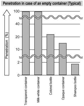
- The graph above is merely a guideline. Penetrating power changes due to container material, thickness and color. We strongly recommend conducting verification tests prior to use.
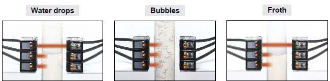
Not affected by drops, bubbles or froth
It is possible to set its sensitivity adjuster so that water drops, bubbles in the water, or froth on the water surface are not detected.
Adjacent sensor mounting possible
Several sensors can be mounted adjacently by fitting optional slit masks.
Further, they can detect the liquid level accurately.
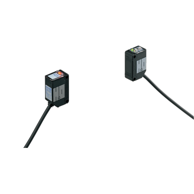
Plug-in connector type is available
Plug-in connector type which enables connection / disconnection of the cable by one-touch is available. Anyone can easily replace the sensor in a minute.
Output operation selectable
Light-ON or Dark-ON operation can be selected.
The output operation can be changed easily.
IP67 protection
The sensor can be hosed down because of its IP67 construction and the non-corrosive stainless steel sensor mounting bracket.
Note: Take care that if it is exposed to water splashes during operation, it will detect the splashed water itself.
Applications
Detecting level of aqueous solution in resin tank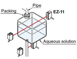
It can reliably detect liquid even in an opaque container.
Detecting the boundary between water and oil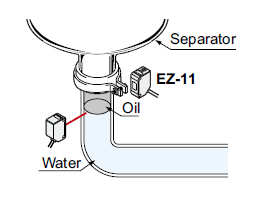
Since it does not detect oil, it can reliably detect the boundary between water and oil.
Detecting presence of liquid in colored bottle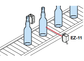
Aqueous liquids in translucent colored bottles can be reliably detected.
Order guide
| Type | Appearance | Sensing range (Note) | Model No. | Output |
|---|---|---|---|---|
| NPN output |
| 5m 16.404 ft (without container or pipe) | EZ-11 | NPN open-collector transistor |
| PNP output | EZ-11-PN | PNP open-collector transistor |
NOTE: Mounting bracket is not supplied with the sensor. Please select from the range of optional sensor mounting brackets (five types).
Notes:
1)The sensing range shortens depending on the thickness, material, color, etc., of the container or pipe.
2)Models whose model name on the product nameplate is followed by “P” are emitters, while those whose model name is followed by “D” are receivers.
5 m 16.404 ft cable length type and plug-in connector type
5 m 16.404 ft cable length type (standard: 2 m 6.562 ft) and plug-in connector type (standard: cable type) are also available.
(5 m 16.404 ft cable length type is not available for the EZ-11-PN.)
When ordering this type, suffix "-C5" for 5 m 16.404 ft cable length type, "-J" for plug-in connector type to the model No.
Please order the suitable mating cable separately for plug-in connector type.
(e.g.) Plug-in connector type of EZ-11-PN is "EZ-11-PN-J ".
- Mating cable for plug-in connector type (2 cables are required)
| Type | Model No. | Description | |
|---|---|---|---|
| Straight | CN-24E-C2 | Length: 2 m 6.562 ft | 0.2 mm2 4-core cabtyre cable with connector on one end Cable outer diameter: Ø3.7 mm Ø0.146 in |
| CN-24E-C5 | Length: 5 m 16.404 ft | ||
| Elbow | CN-24EL-C2 | Length: 2 m 6.562 ft | |
| CN-24EL-C5 | Length: 5 m 16.404 ft | ||
CN-24E-C2, CN-24E-C5
CN-24EL-C2, CN-24EL-C5
Option
| Designation | Model No. | Description | |
|---|---|---|---|
| Round slit mask | OS-CX-05 (Slit size Ø0.5mm Ø0.020 in) | Slit on one side / Sensing range: 200 mm 7.874 in | |
| Slit on both sides / Sensing range: 10 mm 0.394 in | |||
| OS-CX-1 (Slit size Ø1mm Ø0.039 in) | Slit on one side / Sensing range: 400 mm 15.748 in | ||
| Slit on both sides / Sensing range: 60 mm 2.362 in | |||
| OS-CX-2 (Slit size Ø2mm Ø0.079 in) | Slit on one side / Sensing range: 1 m 3.281 ft | ||
| Slit on both sides / Sensing range: 250 mm 9.843 in | |||
| Rectangular slit mask | OS-CX-05x6 (Slit size 0.5 x 6mm 0.020 x 0.236 in) | Slit on one side / Sensing range: 800 mm 31.496 in | |
| Slit on both sides / Sensing range: 250 mm 9.843 in | |||
| OS-CX-1x6 (Slit size 1 x 6mm 0.039 x 0.236 in) | Slit on one side / Sensing range: 1.3 m 4.265 ft | ||
| Slit on both sides / Sensing range: 600 mm 23.622 in | |||
| OS-CX-2x6 (Slit size 2 x 6mm 0.079 x 0.236 in) | Slit on one side / Sensing range: 2 m 6.562 ft | ||
| Slit on both sides / Sensing range: 1.3 m 4.265 ft | |||
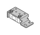
| Sensor mounting bracket (Note 1) | MS-CX2-1 | Foot angled mounting bracket (Two brackets are required.) | |
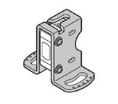
| MS-CX2-2 | Foot biangled mounting bracket (Two brackets are required.) | ||
| MS-CX2-4 | Protective mounting bracket (Two brackets are required.) | ||
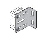
| MS-CX2-5 | Back biangled mounting bracket (Two brackets are required.) | ||
| MS-CX-3 | Back angled mounting bracket (Two brackets are required.) | ||
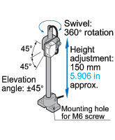
| Universal sensor mounting stand (Note 2) | MS-AJ1 | Horizontal mounting type | Basic assembly |
| MS-AJ2 | Vertical mounting type | ||
| MS-AJ1-A | Horizontal mounting type | Lateral arm assembly | |
| MS-AJ2-A | Vertical mounting type | ||
(Note 1):The plug-in connector type sensor does not allow use of some sensor mounting brackets because of the protrusion of the connector.
(Note 2):Refer to the MS-AJ series for details of the universal sensor mounting stand.
Round slit mask
OS-CX-口
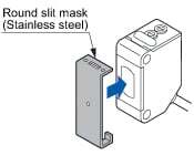
Used for narrowing the beam for cases when detecting water or other substances inside slender pipes.Fitted on the front face of the sensor with one-touch.
Rectangular slit mask
OS-CX-口×6
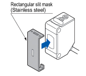
Used for narrowing the beam for cases when detecting water or other substances inside slender pipes.Fitted on the front face of the sensor with one-touch.
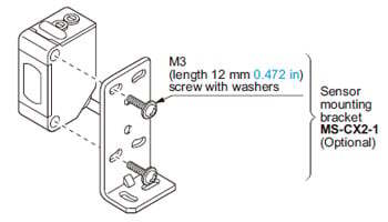
Sensor mounting bracket
MS-CX2-1
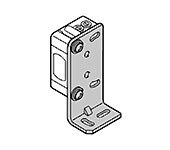
Two M3 (length 12 mm0.472 in) screws with washers are attached.
MS-CX2-2
Two M3 (length 12 mm0.472 in) screws with washers are attached.
MS-CX2-4
Two M3 (length 14 mm0.551 in) screws with washers are attached.
MS-CX2-5

Two M3 (length 12 mm0.472 in) screws with washers are attached.
MS-CX-3
Two M3 (length 12 mm0.472 in) screws with washers are attached.
Universal sensor mounting stand
MS-AJ1
MS-AJ1-A
With the lateral arm, the sensor can sense from above a production line.
![]()
MS-AJ2
MS-AJ2-A
With the lateral arm, the sensor can sense from above a production line.
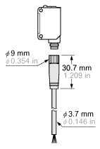
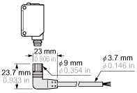
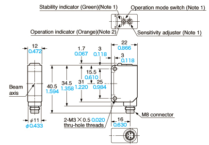
Dimensions
- Unit: mm in
EZ-11 EZ-11-PN
Sensor
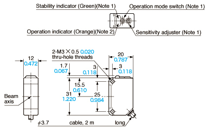
Notes:1) Not incorporated on the emitter.2) It is the power indicator (orange) on the emitter.
EZ-11-PN EZ-11-PN-J
Notes:1) Not incorporated on the emitter.2) It is the power indicator (orange) on the emitter.
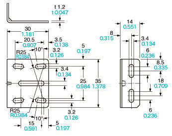
MS-CX2-1
Sensor mounting bracket (Optional)
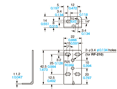
Material:Stainless steel (SUS304)Two M3 (length 12 mm0.472 in) screws with washers are attached.
Assembly dimensions
Mounting drawing with the receiver of EZ-11(-PN)

MS-CX2-2
Sensor mounting bracket (Optional)
Material:Stainless steel (SUS304)Two M3 (length 12 mm0.472 in) screws with washers are attached.
Assembly dimensions
Mounting drawing with the receiver of EZ-11(-PN)
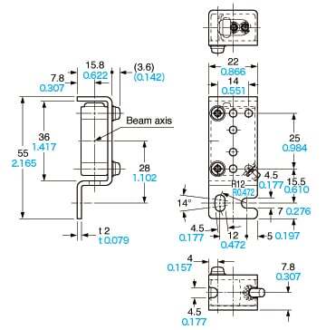
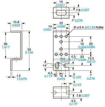
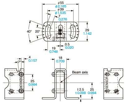
MS-CX2-4
Sensor mounting bracket (Optional)
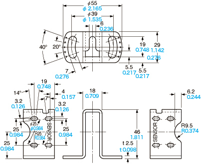
Material:Stainless steel (SUS304)Two M3 (length 14 mm0.551 in) screws with washers are attached.
Assembly dimensions
Mounting drawing with the receiver of EZ-11(-PN)
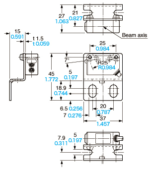
MS-CX2-5
Sensor mounting bracket (Optional)
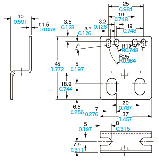
Material:Stainless steel (SUS304)Two M3 (length 12 mm0.472 in) screws with washers are attached.
Assembly dimensions
Mounting drawing with the receiver of EZ-11(-PN)
MS-CX-3
Material:Stainless steel (SUS304)Two M3 (length 12 mm0.472 in) screws with washers are attached.
Assembly dimensions
Mounting drawing with the receiver of EZ-11(-PN)

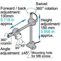
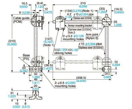
MS-AJ1
Universal sensor mounting stand (Optional)
Two M3 (length 14 mm0.551 in) screws with washers, two M3 (length 16 mm0.630 in) screws with washers, two M3 (length 18 mm0.709 in) screws with washers, one auxiliary mounting plate for EQ-20 series and one auxiliary mounting plate for EX-40 series are attached.Note:The dimensions in the brackets indicate the adjustable range of the movable part.
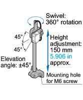
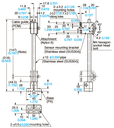
MS-AJ2
Universal sensor mounting stand (Optional)

Two M3 (length 14 mm0.551 in) screws with washers, two M3 (length 16 mm0.630 in) screws with washers, two M3 (length 18 mm0.709 in) screws with washers, one auxiliary mounting plate for EQ-20 series and one auxiliary mounting plate for EX-40 series are attached.Note:The dimensions in the brackets indicate the adjustable range of the movable part.
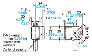
MS-AJ1 MS-AJ2
Universal sensor mounting stand (Optional)
Assembly dimensions (Mounting part only)
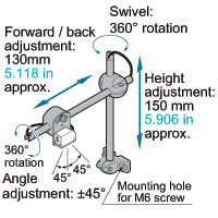
MS-AJ1-A
MS-AJ1-A Universal sensor mounting stand (Optional)
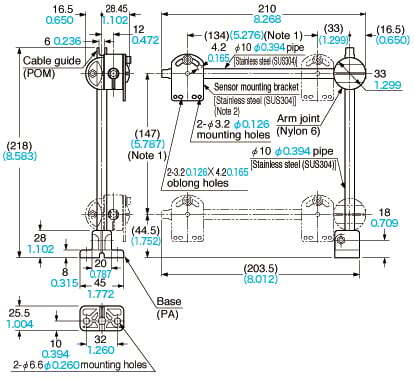
Two M3 (length 14 mm0.551 in) screws with washers, two M3 (length 16 mm0.630 in) screws with washers, two M3 (length 18 mm0.709 in) screws with washers, one auxiliary mounting plate for EQ-20 series and one auxiliary mounting plate for EX-40 series are attached.Notes:1) The dimensions in the brackets indicate the adjustable range of the movable part.2) Refer to MS-AJ1/AJ2 for the assembly dimensions with sensor mounting bracket or sensor.
MS-AJ2-A
MS-AJ2-A Universal sensor mounting stand (Optional)
Two M3 (length 14 mm0.551 in) screws with washers, two M3 (length 16 mm0.630 in) screws with washers, two M3 (length 18 mm0.709 in) screws with washers, one auxiliary mounting plate for EQ-20 series and one auxiliary mounting plate for EX-40 series are attached.Notes:1) The dimensions in the brackets indicate the adjustable range of the movable part.2) Refer to MS-AJ1/AJ2 for the assembly dimensions with sensor mounting bracket or sensor.
I/O Circuit and Wiring diagrams
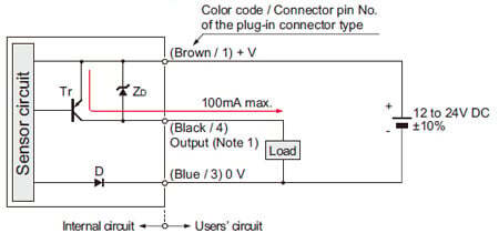
NPN output type
I/O circuit diagram

Notes:
1)The emitter does not incorporate the output.
2)When the mating cable is connected to the plug-in connector type sensor, the white wire of the mating cable is not connected.
Symbols・・・
D : Reverse supply polarity protection diode
ZD: Surge absorption zener diode
Tr: NPN output transistor
Wiring diagram
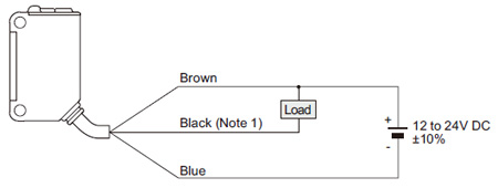
Note: The emitter does not incorporate the black wire.
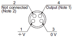
Connector pin position (plug-in connector type)
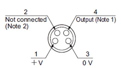
Notes:
1)The emitter does not incorporate the output.
2)When the mating cable is connected to the plug-in connector type sensor, the white wire of the mating cable is not connected.
PNP output type
I/O circuit diagram
Notes:
1)The emitter does not incorporate the output.
2)When the mating cable is connected to the plug-in connector type sensor, the white wire of the mating cable is not connected.
Symbols・・・
D : Reverse supply polarity protection diode
ZD: Surge absorption zener diode
Tr: PNP output transistor
Wiring diagram

Note: The emitter does not incorporate the black wire.
Connector pin position (plug-in connector type)
Notes:
1)The emitter does not incorporate the output.
2)When the mating cable is connected to the plug-in connector type sensor, the white wire of the mating cable is not connected.
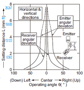
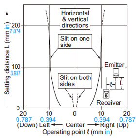
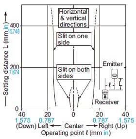
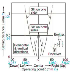
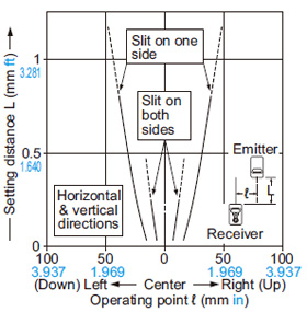
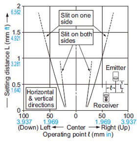
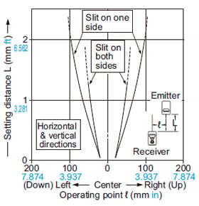
Sensing characteristics
*TYPICAL
Parallel deviation
(ø0.5 mm ø0.020 in)
(ø1 mm ø0.039 in)
(ø2 mm ø0.079 in)
(0.5×6 mm 0.020×0.236 in)
(1×6 mm 0.039×0.236 in)
(2×6 mm 0.079×0.236 in)
Mounting
- The tightening torque should be 0.5 N·m or less.
Wiring
- When connecting the mating cable to the plug-in connector type sensor, the tightening torque should be 0.4 N·m or less.
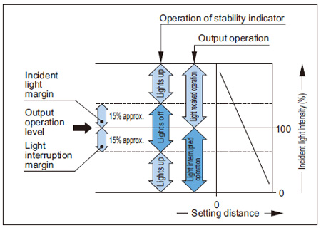
Stability indicator
Others
- This product has been developed / produced for industrial use only.
- This product is suitable for indoor use only.
- Because these units use special emitter and receiver elements, they are susceptible to the effects of operating ambient temperature and humidity. Sensitivity adjustment should be performed in the environment in which they will actually be used.
- Do not use during the initial transient time (100 ms) after the power supply is switched on.