Basic Information
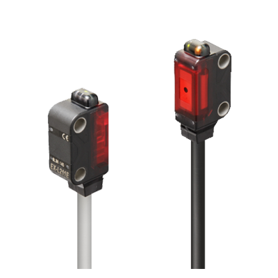
Introducing ultra-compact amplifier built-in laser sensor


GB : Conforming to 7247.1
Features
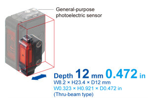
Ultra-compact
Due to the customized IC and optical design, high precision detection is fulfilled with directivity and visibility achievable only by laser. The laser adopted is Class 1 (IEC/EN/JIS/GB/KS/FDA) laser that is safe to use, so that there is no need to separate the areas of sensor usage.
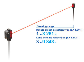
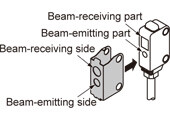
THRU-BEAM TYPE
Minute object detection type [EX-L211]
Spread the beam and lower its density, thus even a minute object can be detected with a small change in the light received intensity. Spot size: 6 × 4 mm 0.236 × 0.157 in approx. (Visual reference value at a distance from the emitter of 1 m 3.281 ft)
Long sensing range type [EX-L212]
A long range detection of 3 m 9.843 ft is achieved. High precision detection with minimum beam spread is possible even in a long range.
Spot size: 8 × 5.5 mm 0.315 × 0.217 in approx. (Visual reference value at a distance from the emitter of 1 m 3.281 ft)
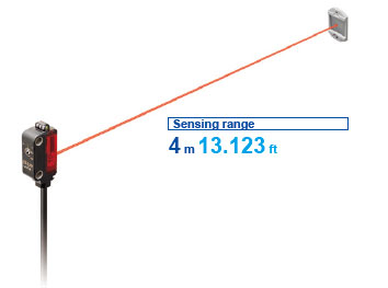
RETROREFLECTIVE TYPE
Long sensing range type [EX-L291]
Achieving ease of installation and 4 m 13.123 ft long sensing range.
Spot size: 6 × 4 mm 0.236 × 0.157 in approx. (Visual reference value at a distance from the emitter of 1 m 3.281 ft)
SPOT REFLECTIVE TYPE
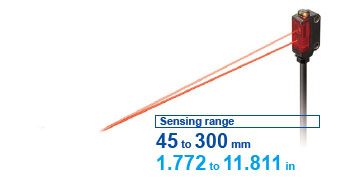
Minute object detection type [EX-L221]
Highly precise sensing with minimum 0.01 mm 0.0004 in diameter. Many applications are possible due to the 300 mm 11.811 in long sensing range.
Spot size: ø1 mmø0.039 in or less (Reference value at a distance from the emitter of 300 mm 11.811 in)
CONVERGENT REFLECTIVE TYPE
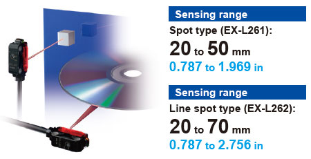
Spot type [EX-L261]
Highly precise sensing with minimum 0.01 mm 0.0004 in diameter. Not affected by the background, and able to reliably sense unevenly-colored workpieces.
Spot size: ø1 mm ø0.039 in or less (Reference value at a sensing distance of 50 mm 1.969 in)
Line spot type [EX-L262]
Able to sense thin, glossy or curved-surface workpieces due to line beam.
Spot size: 5 × 1 mm 0.197 × 0.039 in approx. (Visual reference value at a sensing distance of 50 mm 1.969 in)

Highly accurate detection [EX-L211/L221]
Suitable for positioning and minute object detection
| Model No. (Minute object detection type) | Minimum sensing object (Typical) | Repeatability (Typical) |
|---|---|---|
| EX-L211 (Thru-beam type) | ø0.3 mm ø0.012 in | 0.01 mm 0.0004 in or less |
| EX-L221 (Spot reflective type) | ø0.01 mm ø0.0004 in | 0.02 mm 0.0008 in or less |
*Typical values when the sensitivity adjuster is optimally adjusted.
A repeatability of 0.02 mm 0.0008 in or less at a range of from 100 to 200 mm 3.937 to 7.874 in makes this type best suitable for positioning applications (typical, EX-L221). Moreover, it boasts a top-class detection precision in the compact laser sensor category with the gold wire of ø0.01 mm ø0.0004 in.
Dependable technology yields high precision
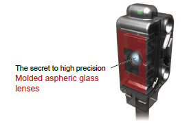
Incorporating a high-precision aspheric glass lens
Light aberrations are reduced and a high definition laser spot is possible by incorporating a molded aspheric glass lens.
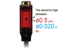
Small receiver aperture for precision detection [EX-L211/L212]
Errant beams are eliminated by the ø0.5 mm ø0.020 in receiver aperture. Only beams entering the aperture are used, making for high-precision sensing.
Stable convergent distance sensing
For sensing when background object presents
Due to convergent distance sensing, the background has very little effect, enabling stable sensing. Sensitivity adjuster allows you to adjust sensitivity to avoid sensing background objects when the distance between the workpiece and background objects is small.
For sensing unevenly-colored workpieces
Able to reliably sense unevenly-colored workpieces.

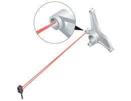
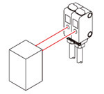
Easy beam-axis alignment [EX-L211/EX-L212]
Visual positioning is easy due to silhouetting a sensing object against a receiver.
Visually confirm the optimal receiver position, adjusting the beam axis by aligning the objects while watching the red spot on the beam alignment screen. The diagram on the right shows an example with the lead of a mechanical pencil being detected through visual adjustment.
![Easy beam-axis alignment [EX-L211/EX-L212]](https://ap.industry.panasonic.com/hubfs/pid-corp/products/fasys/sensor/photoelectric/ex-l200/images/pic07.jpg)

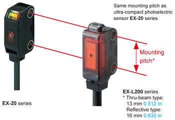
Same mounting pitch as ultra-compact photoelectric sensor
EX-L200 series has the same mounting pitch as ultra-compact photoelectric sensor EX-20 series so that the time taken in designing is saved.

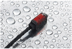
Strong against water and dust with protection structure IP67
The sensor can be used even in environment where water or dust present because of its protection structure IP67.

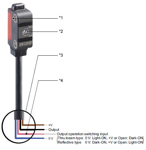
M3 screw used for secure tightening (*1)
The mounting holes have metal sleeves inserted to prevent damage to the sensor due to over tightening of the screws.
(Tightening torque: 0.5 N.m)

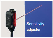
Sensitivity adjuster (excluding EX-L212□) (*2)
A sensitivity adjuster of small size is incorporated to offer strong performance in minute detection or high precision detection.
Low current consumption (*2)
The laser light source contributes to low current consumption, as it is approx. 5 mA lower than a LED light source.
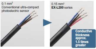
Conductor thickness 1.5 times increased to make wiring easier (*3)
The lead wire conductor’s thickness is increased to 0.15 mm2 from 0.1 mm2 of the conventional ultra-compact photoelectric sensor. This makes it easier to perform crimpling work on the cables for better workability. In addition, the tensile strength of the crimpling area has become stronger.
Switchable output operation (*4)
The output operation switching input enables the switching of Light-ON or Dark-ON in one unit. This prevents ordering mistake and reduces the maintenance of spare parts.
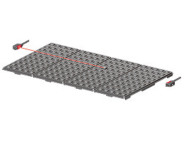
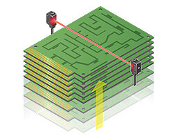
Applications
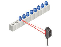
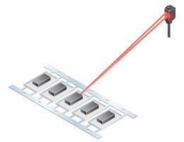
Detecting ICs that are out of position in multiple palettes
Confirming arrival of substrate
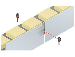
Detecting objects from an opening
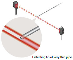
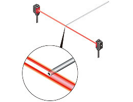
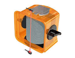
Detecting tip of very thin pipe
Checking protrusion of wafer
Determining electric parts position
Detecting processed holes
Detecting chip components
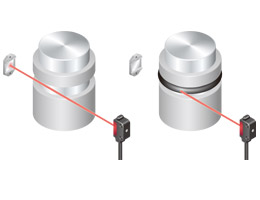
Detecting O-ring
Checking protrusion of tray in storage
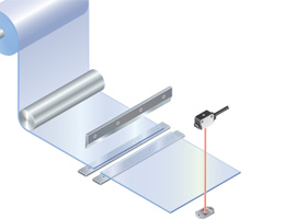
Determining cutting position of sheet
Sensing unevenly-colored workpieces
Sensing thin workpiece such as PCB
Sensing glossy or curved-surface workpiece
Order guide
| Type | Appearance | Sensing range | Model No. | Emission spot size (Typical) | Sensitivity adjuster | ||
|---|---|---|---|---|---|---|---|
| NPN output | PNP output | ||||||
| Thru-beam | Minute object detection |
| 1m 3.281 ft | EX-L211 | EX-L211-P | Approx. 6 x 4 mm 0.236 x 0.157 in (at a sensing distance of 1 m 3.281 ft) | Incorporated |
| Long sensing range | 3m 9.843ft | EX-L212 | EX-L212-P | Approx. 8 x 5.5 mm 0.315 x 0.217 in (at a sensing distance of 1 m 3.281 ft) | - | ||
| Retroreflective | Long sensing range |
| 4m 13.123ft (Note 2) | EX-L291 | EX-L291-P | Approx. 6 x 4 mm 0.236 x 0.157 in (at a sensing distance of 1 m 3.281 ft) | Incorporated |
| Spot reflective | Minute object detection |
| 45 to 300 mm 1.772 to11.811 in | EX-L221 | EX-L221-P | ø1 mm ø0.039 in or less (at a sensing distance of 300 mm 11.811 in) | Incorporated |
| Convergent reflective | Spot |
| 20 to 50 mm 0.787 to 1.969 in (Convergent point: 22 mm 0.866 in) (Note 3) | EX-L261 | EX-L261-P | ø1 mm ø0.039 in or less (at a sensing distance of 50 mm 1.969 in) | Incorporated |
| Line spot |
| 20 to 70 mm 0.787 to 2.756 in (Convergent point:22 mm 0.866 in) (Note 3) | EX-L262 | EX-L262-P | Approx. 5 x 1 mm 0.197 x 0.039 in (at a sensing distance of 50 mm 1.969 in) | Incorporated | |


Note 1:The model No. with "E" shown on the label affixed to the thru-beam type sensor is the emitter, "D" shown on the label is the receiver.
Note 2:The sensing range is the value for RF-330 reflector. The sensing range represents the actual sensing range of the sensor. The sensing ranges itemized in "A" of the table below may vary depending on the shape of sensing object. Be sure to check the operation with the actual sensing object.
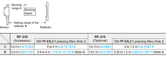
Note 3:The sensing range is specified for white non-glossy paper (100 × 100 mm 3.937 × 3.937 in) as the object.
Note 4:Refer to OPTIONS for the polarizing filter PF-EXL2-1 and the reflector RF-210.
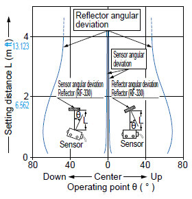
Note 5:When positioning the reflector nearby, the angular characteristic become more narrow. Adjust the angle of a sensor or reflector.
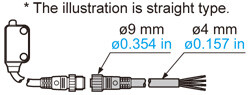
M8 pigtailed type and 5 m 16.404 ft cable length type
M8 pigtailed type and 5 m 16.404 ft cable length type (standard: 2 m 6.562 ft) are also available.
When ordering these types, suffix "-J" for the M8 pigtailed type, "-C5" for the 5 m 16.404 ft cable length type to the model No.
Please order the mating cable the M8 pigtailed type separately.
(e.g.)
M8 pigtailed type of EX-L211-P is "EX-L211-P-J"
5 m 16.404 ft cable length type of EX-L211-P is "EX-L211-P-C5"
M8 pigtailed type
| Standard type | M8 pigtailed type |
|---|---|
| EX-L261 | EX-L261-J |
| EX-L261-P | EX-L261-P-J |
| EX-L262 | EX-L262-J |
| EX-L262-P | EX-L262-P-J |
| EX-L211 | EX-L211-J |
| EX-L211-P | EX-L211-P-J |
| EX-L212 | EX-L212-J |
| EX-L212-P | EX-L212-P-J |
| EX-L291 | EX-L291-J |
| EX-L291-P | EX-L291-P-J |
| EX-L221 | EX-L221-J |
| EX-L221-P | EX-L221-P-J |
5 m 16.404 ft cable length type
| Standard type | 5 m 16.404 ft cable length type |
|---|---|
| EX-L261 | EX-L261-C5 |
| EX-L261-P | EX-L261-P-C5 |
| EX-L262 | EX-L262-C5 |
| EX-L262-P | EX-L262-P-C5 |
| EX-L211 | EX-L211-C5 |
| EX-L211-P | EX-L211-P-C5 |
| EX-L212 | EX-L212-C5 |
| EX-L212-P | EX-L212-P-C5 |
| EX-L291 | EX-L291-C5 |
| EX-L291-P | EX-L291-P-C5 |
| EX-L221 | EX-L221-C5 |
| EX-L221-P | EX-L221-P-C5 |
Mating cable
CN-24A-C2 CN-24AL-C2
CN-24A-C5 CN-24AL-C5
・Mating cable (2 cables are required for the thru-beam type.)
| Type | Model No. | Cable length |
|---|---|---|
| Straight | CN-24A-C2 | 2 m 6.562 ft |
| CN-24A-C5 | 5 m 16.404 ft | |
| Elbow | CN-24AL-C2 | 2 m 6.562 ft |
| CN-24AL-C5 | 5 m 16.404 ft |
Package without reflector
Retroreflective type is also available without the reflector.
| Type | Model No. | ||
|---|---|---|---|
| NPN output | PNP output | ||
| Retroreflective type | EX-L291-Y | EX-L291-P-Y | |
| M8 pigtailed type | EX-L291-J-Y | EX-L291-P-J-Y | |
| 5 m 16.404 ft cable length type | EX-L291-C5-Y | EX-L291-P-C5-Y | |
Accessory
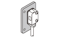
MS-EXL2-2 (Mounting plate for thru-beam type): 1 pc.
MS-EXL2-3 (Mounting plate for retroreflective / spot reflective / convergent reflective type): 1 pc.
RF-330 (Reflector): 1 pc.
Option
| Designation | Model No. | Description |
|---|---|---|
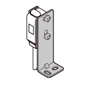
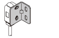
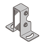
| Sensor mounting bracket | MS-EXL2-1 | Foot angled mounting bracket (The thru-beam type sensor needs two brackets.) |
| MS-EXL2-5 | Back angled mounting bracket (The thru-beam type sensor needs two brackets.) | |
| MS-EXL2-6 | Compatible bracket for thru-beam type A bracket to easily mount EX-L21□ on the 25.4 mm 1.000 in pitch sensor mounting bracket: Use with the mounting plate attached to the sensor. Two brackets are needed when used for the emitter and the receiver. | |
| Universal sensor mounting bracket | MS-EXL2-4 | It can adjust the height and the angle of the sensor. (The thru-beam type sensor needs two brackets.) |
| Polarizing filter | PF-EXL2-1 | For retroreflective type EX-L291□ Stabilizes sensitivity of the reflective surface. |
| Reflector | RF-210 | For retroreflective type EX-L291□ Sensing range: 1.8 m 5.906 in (Note) |
| Reflector mounting bracket | MS-RF21-1 | Protective mounting bracket for RF-210 It protects the reflector from damage and maintains alignment. |
Note:
Set the distance between the reflector and sensor to be at least 0.16 m 0.525 in.
Refer to "ORDER GUIDE" for details.
Sensor mounting bracket
MS-EXL2-1
Material:Stainless steel (SUS304)Two M3 (length 14 mm0.551 in) screws with washers [stainless steel (SUS304)] are attached.
MS-EXL2-5
Material: Stainless steel (SUS)Two M3 (length 14 mm0.551 in) screws with washers [stainless steel (SUS)] are attached.
MS-EXL2-6
Material: Stainless steel (SUS304)Two M3 (length 12 mm0.472 in) screws with washers [stainless steel (SUS)] are attached.
Polarizing filter
PF-EXL2-1
Material: Stainless steel (SUS304)
Reflector
RF-210
Reflector mounting bracket
MS-RF21-1
Two M3 (length 12 mm0.472 in)screws with washers are attached.
Universal sensor mounting bracket
MS-EXL2-4
Two M3 (length 14 mm0.551 in) screws with washers, one M3 (length 10 mm0.394 in) hexagon-socket head bolt [stainless steel (SUS)], and one M3 hexagon nut [stainless steel (SUS)] are attached.
Recommended e-CON connector
Manufactured by 3M Japan Limited
Adapted connector:37104-3101-000 FL
Please refer to "Introducing the 3M™ mini-clamp connector" for details.
Specifications
Thru-beam type
| Type | Thru-beam | ||
|---|---|---|---|
| Minute object detection | Long sensing range | ||
| Model No. | NPN output | EX-L211 | EX-L212 |
| PNP output | EX-L211-P | EX-L212-P | |
| Applicable regulations and certifications | CE Marking (EMC Directive, RoHS Directive), UKCA Marking (EMC Regulations, RoHS Regulations), FDA Regulations, Chinese Standard GB 7247.1 | ||
| Sensing range | 1 m 3.281 ft | 3 m 9.843 ft | |
| Emission spot size (Typical) | Approx. 6 × 4 mm 0.236 × 0.157 in (vertical × horizontal) (at a sensing distance of 1 m) | Approx. 8 × 5.5 mm 0.315 × 0.217 in (vertical × horizontal) (at a sensing distance of 1 m) (Note 2) | |
| Sensing object | Opaque object of ø2 mm ø0.079 in or more | Opaque object of ø3 mm ø0.118 in or more | |
| Minimum sensing object (Typical) (Note 3) | Opaque object of ø0.3 mm ø0.012 in | - | |
| Repeatability | Perpendicular to sensing axis: 0.05 mm 0.0020 in or less | ||
| Repeatability (Typical) (perpendicular to sensing axis) (Note 3) | 0.01 mm 0.0004 in or less (all area) | - | |
| Supply voltage | 12 to 24 V DC ±10 % Ripple P-P 10 % or less | ||
| Current consumption | Emitter: 10 mA or less, Receiver: 10 mA or less | ||
| Output | <NPN output type> NPN open-collector transistor ・Maximum sink current: 50 mA ・Applied voltage: 26.4 V DC or less (between output and 0 V) ・Residual voltage: 2 V or less (at 50 mA sink current) 1 V or less (at 16 mA sink current) <PNP output type> PNP open-collector transistor ・Maximum source current: 50 mA ・Applied voltage: 26.4 V DC or less (between output and +V) ・Residual voltage: 2 V or less (at 50 mA source current) 1 V or less (at 16 mA source current) | ||
| Output operation | Light-ON / Dark-ON selectable by the output operation switching input | ||
| Short-circuit protection | Incorporated (short-circuit protection / inverse polarity protection) | ||
| Response time | 0.5 ms or less | ||
| Operation indicator | Orange LED (lights up when the output is ON) (incorporated on the receiver for thru-beam type) | ||
| Stability indicator | Green LED (lights up under stable light received condition or stable dark condition) (incorporated on the receiver for thru-beam type) | ||
| Power indicator | Green LED (lights up when the power is ON) (incorporated on the emitter) | ||
| Sensitivity adjuster | Continuously variable adjuster (receiver) | - | |
| Protection | IP67 (IEC) | ||
| Ambient temperature | -10 to +55 ℃ +14 to +131 ℉ (No dew condensation or no icing condition), Storage: -30 to +70 ℃ -22 to +158 ℉ | ||
| Ambient humidity | 35 to 85 % RH, Storage: 35 to 85 % RH | ||
| Ambient illuminance | Incandescent light: 3,000 lx or less at the light-receiving face | ||
| Voltage withstandability | 1,000 V AC for one min. between all supply terminals connected together and enclosure | ||
| Insulation resistance | 20 MΩ, or more, with 250 V DC megger between all supply terminals connected together and enclosure | ||
| Vibration resistance | 10 to 500 Hz frequency, 1.5 mm 0.059 in double amplitude (10 G max.) in X, Y and Z directions for two hours each | ||
| Shock resistance | 500 m/s2 acceleration (50 G approx.) in X, Y and Z directions three times each | ||
| Emitting element | Red semiconductor laser Class 1 (IEC/EN/JIS/GB/KS/FDA) (Note 4) (Maximum output: 1 mW, Peak emission wavelength: 655 nm 0.026 mil) | ||
| Material | Enclosure: Polybutylene terephthalate, Front cover: Acylic, Lens: Glass, Indicator part: Polyarylate | ||
| Cable | 0.15 mm2 4-core (emitter of a thru-beam type: 2-core) cabtyre cable, 2 m 6.562 ft long | ||
| Cable extension | Extension up to total 50 m 164.042 ft is possible with 0.3 mm2, or more, cable (thru-beam type: Total 100 m 328.084 ft both emitter and receiver). | ||
| Weight | Net weight: Emitter; 40 g approx., Receiver; 40 g approx., Gross weight: 90 g approx. | ||
| Accessory | MS-EXL2-2 (Mounting plate): 2 pcs. | ||
Notes :
1)Where measurement conditions have not been specified precisely, the conditions used were an ambient temperature of +23 ℃ +73.4 ℉
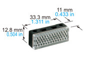
2)In the case sensing distance is 3 m 9.843 ft, the emission spot size is H 17 × W 11 mm H 0.669 × W 0.433 in (visual reference value).
3)Typical values when the sensitivity adjuster is optimally adjusted.
4)This product complies with the FDA regulations (FDA 21 CFR 1040.10 and 1040.11) in accordance with FDA Laser Notice No. 56, except for complying with IEC 60825-1 Ed. 3.
Reflective type
| Type | Retroreflective | Spot reflective | |
|---|---|---|---|
| Long sensing range | Minute object detection | ||
| Model No. | NPN output | EX-L291 | EX-L221 |
| PNP output | EX-L291-P | EX-L221-P | |
| Applicable regulations and certifications | CE Marking (EMC Directive, RoHS Directive), UKCA Marking (EMC Regulations, RoHS Regulations), FDA Regulations, Chinese Standard GB 7247.1 | ||
| Sensing range | 4 m 13.123 ft (Note 2) | 45 to 300 mm 1.772 to 11.811 in (Note 3) | |
| Emission spot size (Typical) | Approx. 6 × 4 mm 0.236 × 0.157 in (vertical x horizontal) (at a sensing distance of 1 m) (Note 4) | ø1 mm ø0.039 in or less (at a sensing distance of 300 mm) | |
| Sensing object | Opaque translucent object of ø25 mm ø0.984 in or more | Opaque, translucent or transparent object (Note 7) | |
| Minimum sensing object (Typical) (Note 5) | - | Gold wire of ø0.01 mm ø0.0004 in | |
| Hysteresis | 20 % or less of operation distance | ||
| Repeatability | Perpendicular to sensing axis: 0.2 mm 0.0080 in or less | ||
| Repeatability (Typical) (perpendicular to sensing axis) (Note 5) | - | 0.02 mm 0.0008 in or less (at 100 to 200 mm sensing distance) | |
| Supply voltage | 12 to 24 V DC ±10 % Ripple P-P 10 % or less | ||
| Current consumption | 15 mA or less | ||
| Output | <NPN output type> NPN open-collector transistor ・Maximum sink current: 50 mA ・Applied voltage: 26.4 V DC or less (between output and 0 V) ・Residual voltage: 2 V or less (at 50 mA sink current) 1 V or less (at 16 mA sink current) <PNP output type> PNP open-collector transistor ・Maximum source current: 50 mA ・Applied voltage: 26.4 V DC or less (between output and +V) ・Residual voltage: 2 V or less (at 50 mA source current) 1 V or less (at 16 mA source current) | ||
| Output operation | Light-ON / Dark-ON selectable by the output operation switching input | ||
| Short-circuit protection | Incorporated (short-circuit protection / inverse polarity protection) | ||
| Response time | 0.5 ms or less | ||
| Operation indicator | Orange LED (lights up when the output is ON) (incorporated on the receiver for thru-beam type) | ||
| Stability indicator | Green LED (lights up under stable light received condition or stable dark condition) (incorporated on the receiver for thru-beam type) | ||
| Automatic interference prevention function | Incorporated (Two sensors can be mounted close together.) | ||
| Sensitivity adjuster | Continuously variable adjuster | ||
| Protection | IP67 (IEC) | ||
| Ambient temperature | -10 to +55 ℃ +14 to +131 ℉ (No dew condensation or no icing condition), Storage: -30 to +70 ℃ -22 to +158 ℉ | ||
| Ambient humidity | 35 to 85 % RH, Storage: 35 to 85 % RH | ||
| Ambient illuminance | Incandescent light: 3,000 lx or less at the light-receiving face | ||
| Voltage withstandability | 1,000 V AC for one min. between all supply terminals connected together and enclosure | ||
| Insulation resistance | 20 MΩ, or more, with 250 V DC megger between all supply terminals connected together and enclosure | ||
| Vibration resistance | 10 to 500 Hz frequency, 1.5 mm 0.059 in double amplitude (10 G max.) in X, Y and Z directions for two hours each | ||
| Shock resistance | 500 m/s2 acceleration (50 G approx.) in X, Y and Z directions three times each | ||
| Emitting element | Red semiconductor laser Class 1 (IEC/EN/JIS/GB/KS/FDA) (Note 8) (Maximum output: EX-L291□ 0.5 mW, EX-L221□ 2 mW, Peak emission wavelength: 655 nm 0.026 mil) | ||
| Material | Enclosure: Polybutylene terephthalate, Front cover: Acylic, Lens: Glass, Indicator part: Polyarylate | ||
| Cable | 0.15 mm2 4-core (emitter of a thru-beam type: 2-core) cabtyre cable, 2 m 6.562 ft long | ||
| Cable extension | Extension up to total 50 m 164.042 ft is possible with 0.3 mm2, or more, cable. | ||
| Weight | Net weight: 45 g approx., Gross weight: 60 g approx. | ||
| Accessory | RF-330 (Reflector): 1 pc. MS-EXL2-3 (Mounting plate): 1 pc. | MS-EXL2-3 (Mounting plate): 1 pc. | |
Notes :
1)Where measurement conditions have not been specified precisely, the conditions used were an ambient temperature of +23 ℃ +73.4 ℉
2)The sensing range is the value for RF-330 reflector. The sensing range represents the actual sensing range of the sensor. The sensing ranges itemized in " A " of the table below may vary depending on the shape of sensing object. Be sure to check the operation with the actual sensing object.
*1 Refer to "OPTIONS" for the polarizing filter PF-EXL2-1 and the reflector RF-210.
*2 When positioning the reflector nearby, the angular characteristic become more narrow. Adjust the angle of a sensor or reflector.
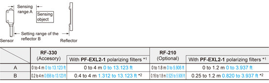
3)The sensing range is specified for white non-glossy papar (100 × 100 mm 3.937 × 3.937 in) as the object.
4)In the case sensing distance is 4 m 13.123 ft, the emission spot size is H 18 × W 10 mm H 0.709 × W 0.394 in (visual reference value).
5)These values were defined by using 1/e2 (13.5 % approx.) of the center light intensity.
6)Typical values when the sensitivity adjuster is optimally adjusted.
7)Make sure to confirm detection with an actual sensor before use.
8)This product complies with the FDA regulations (FDA 21 CFR 1040.10 and 1040.11) in accordance with FDA Laser Notice No. 56, except for complying with IEC 60825-1 Ed. 3.
Convergent reflective type
| Type | Convergent reflective | ||
|---|---|---|---|
| Spot | Line spot | ||
| Model No. | NPN output | EX-L261 | EX-L262 |
| PNP output | EX-L261-P | EX-L262-P | |
| Applicable regulations and certifications | CE Marking (EMC Directive, RoHS Directive), UKCA Marking (EMC Regulations, RoHS Regulations), FDA Regulations, Chinese Standard GB 7247.1 | ||
| Sensing range | 20 to 50 mm 0.787 to 1.969 in (Convergent point: 22 mm 0.866 in) (Note 2) | 20 to 70 mm 0.787 to 2.756 in (Convergent point: 22 mm 0.866 in) (Note 2) | |
| Emission spot size (Typical) | ø1mm 0.039 in or less (at a sensing distance of 50 mm) (Note 3) | Approx. 5 × 1 mm 0.197 × 0.039 in (vertical × horizontal) (at a sensing distance of 50 mm) | |
| Sensing object | Opaque, translucent or transparent object (Note 4) | ||
| Minimum sensing object (Typical) (Note 5) | Gold wire of ø0.01 mm ø0.0004 in | - | |
| Hysteresis | 20 % or less of operation distance | ||
| Repeatability | Perpendicular to sensing axis: 0.2 mm 0.0080 in or less | ||
| Repeatability (Typical) (perpendicular to sensing axis) (Note 5) | 0.02 mm 0.0008 in or less (at 100 to 200 mm sensing distance) | - | |
| Supply voltage | 12 to 24 V DC ±10 % Ripple P-P 10 % or less | ||
| Current consumption | 15 mA or less | ||
| Output | <NPN output type> NPN open-collector transistor ・Maximum sink current: 50 mA ・Applied voltage: 26.4 V DC or less (between output and 0 V) ・Residual voltage: 2 V or less (at 50 mA sink current) 1 V or less (at 16 mA sink current) <PNP output type> PNP open-collector transistor ・Maximum source current: 50 mA ・Applied voltage: 26.4 V DC or less (between output and +V) ・Residual voltage: 2 V or less (at 50 mA source current) 1 V or less (at 16 mA source current) | ||
| Output operation | Light-ON / Dark-ON selectable by the output operation switching input | ||
| Short-circuit protection | Incorporated (short-circuit protection / inverse polarity protection) | ||
| Response time | 0.5 ms or less | ||
| Operation indicator | Orange LED (lights up when the output is ON) (incorporated on the receiver for thru-beam type) | ||
| Stability indicator | Green LED (lights up under stable light received condition or stable dark condition) (incorporated on the receiver for thru-beam type) | ||
| Automatic interference prevention function | Incorporated (Two sensors can be mounted close together.) | ||
| Sensitivity adjuster | Continuously variable adjuster | ||
| Protection | IP67(IEC) | ||
| Ambient temperature | -10 to +55℃ +14 to +131℉(No dew condensation or icing allowed), Storage: –30 to +70℃ –22 to +158℉ | ||
| Ambient humidity | 35 to 85%RH , Storage:35 to 85%RH | ||
| Emitting element | Red semiconductor laser Class 1 (IEC/EN/JIS/GB/KS/FDA) (Note 6) (Maximum output: EX-L261□ 1 mW, EX-L262□ 1.3 mW, Peak emission wavelength: 655 nm 0.026 mil) | ||
| Material | Enclosure: Polybutylene terephthalate, Front cover: Acylic, Lens: Glass, Indicator part: Polyarylate | ||
| Cable | 0.15 mm2 4-core cabtyre cable, 2 m 6.562 ft long | ||
| Cable extension | Extension up to total 50 m 164.042 ft is possible with 0.3 mm2, or more, cable | ||
| Weight | Net weight: 45 g approx., Gross weight: 60 g approx. | ||
| Accessory | MS-EXL2-3 (Mounting plate): 1 pc. | ||
Notes :
1)Where measurement conditions have not been specified precisely, the conditions used were an ambient temperature of +23 ℃ +73.4 ℉
2)The sensing range is specified for white non-glossy papar (100 × 100 mm 3.937 × 3.937 in) as the object.
3)These values were defined by using 1/e2 (13.5 % approx.) of the center light intensity.
4)Make sure to confirm detection with an actual sensor before use.
5)Typical values when the sensitivity adjuster is optimally adjusted.
6) This product complies with the FDA regulations (FDA 21 CFR 1040.10 and 1040.11) in accordance with FDA Laser Notice No. 56, except for complying with IEC 60825-1 Ed. 3.
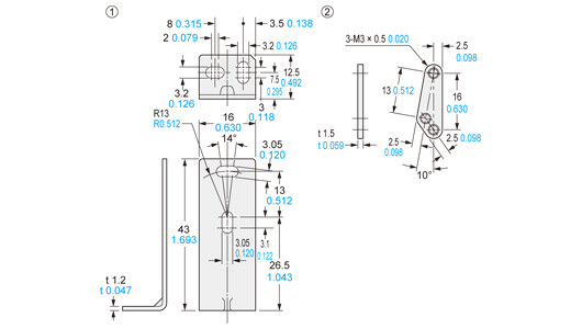
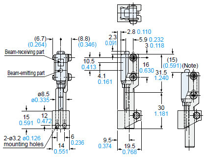
Dimensions
- Unit: mm in
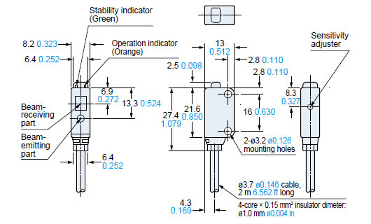
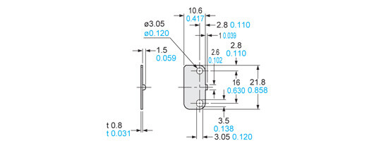
EX-L211(-P)
EX-L212(-P)
Sensor
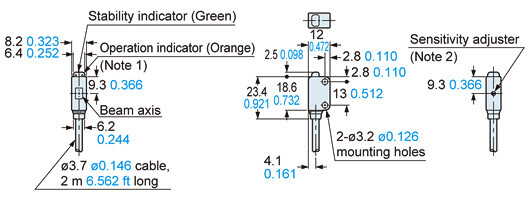
Notes:1) It is the laser radiation indicator (green) on the emitter.2) It is incorporated in EX-L211(-P) only.
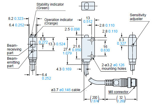
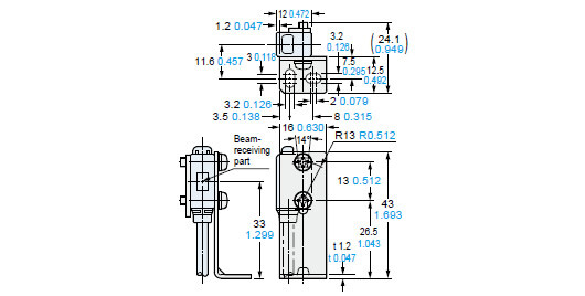
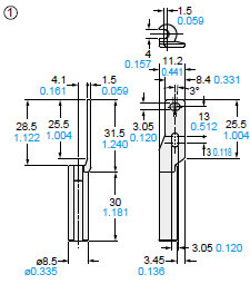
EX-L211(-P)-J
EX-L212(-P)-J
Sensor
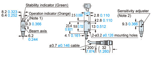
Notes:1) It is the laser radiation indicator (green) on the emitter.2) It is incorporated in EX-L211(-P)-J only.
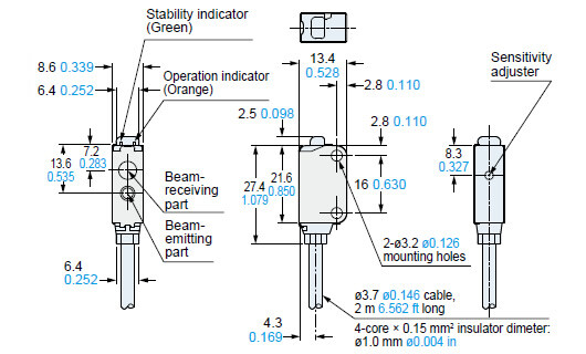
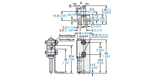
EX-L291(-P)
EX-L221(-P)
Sensor
Assembly dimensions with polarizing filter (PF-EXL2-1)
Mounting drawing with EX-L291(-P)
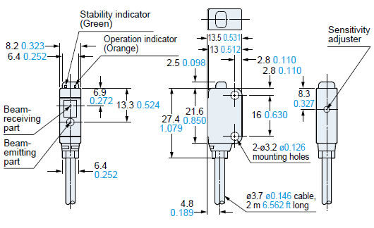
EX-L291(-P)-J
EX-L221(-P)-J
Sensor
EX-L261(-P)
EX-L262(-P)
Sensor
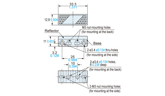
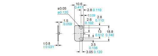
RF-330
Reflector (Accessory for EX-L291□)
Material:Acrylic (Reflector)ABS (Base)
RF-210
Reflector (Optional)
Material: Acrylic (Reflector)ABS (Base)Two M3 (length 8 mm0.315 in)screws with washers and two nuts are attached.
MS-RF21-1
Reflector mounting bracket for RF-210 (Optional)
Material:Stainless steel (SUS304)Two M3 (length 12 mm0.472 in) screws with washers are attached.
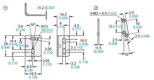
Assembly dimensions
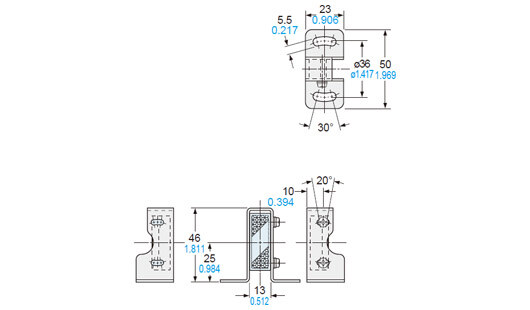
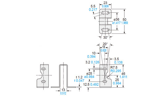
MS-EXL2-1
Sensor mounting bracket (Optional)
Material: Stainless steel (SUS304)Two M3 (length 14 mm0.551 in) screws with washers [stainless steel (SUS304)] are attached.
Assembly dimensions
Mounting drawing with the receiver of EX-L211□/L212□
Mounting drawing with EX-L291□/L221□/L261□/L262□
Model No.ABEX-L291□ / L221□130.5122.20.087EX-L261□ / L262□13.50.5322.70.106
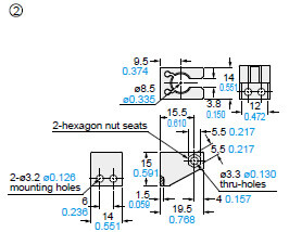
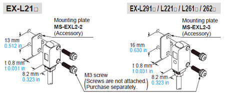
MS-EXL2-2
Mounting plate (Accessory for EX-L211□/L212□)
Material: Stainless steel (SUS304)Note:Screws are not attached.Purchase separately.
Assembly dimensions
Mounting drawing with the emitter

* Without using the mounting plate, beam misalignment may occur.
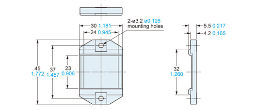
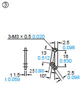
MS-EXL2-3
Mounting plate (Accessory for EX-L291□/L221□/L26□)
Material: Stainless steel (SUS304)Note:Screws are not attached.Purchase separately.
Assembly dimensions

* Without using the mounting plate, beam misalignment may occur.
MS-EXL2-4
Universal sensor mounting bracket (Optional)
Assembly dimensions
Material: Die-cast zinc alloyTwo M3 (length 14 mm0.551 in) screws with washers [stainless steel (SUS)], one M3 (length 10 mm0.394 in) hexagon socket-head bolt [stainless steel (SUS)], and one M3 hexagon nut [stainless steel (SUS)] are attached.
Material: Die-cast zinc alloy
Material: Stainless steel (SUS)
Mounting drawing with the receiver of EX-L211□/L212□

Note: This is the adjustable range of the movable part.
Mounting drawing with EX-L291□/L221□
Note: This is the adjustable range of the movable part.
MS-EXL2-5
Sensor mounting bracket (Optional)
Back angled mounting bracket
Material: Stainless steel (SUS304)Two M3 (length 14 mm0.551 in) screws with washers [stainless steel (SUS)] are attached.
I/O Circuit and Wiring diagrams
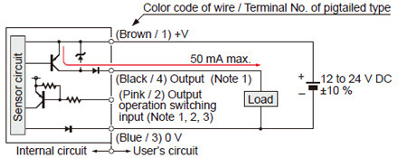
NPN output type
I/O circuit diagrams
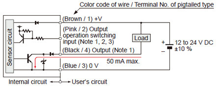
Notes:
1)The emitter of a thru-beam type does not incorporate output (black / 4) and output operation switching input (pink / 2).
2)Be able to select either Light-ON or Dark-ON by wiring the output operation switching input (pink / 2) as shown in the following table.
| Type | Light-ON | Dark-ON |
|---|---|---|
| Thru-beam, Retroreflective | Connect to 0 V | Connect to + V or, Open |
| Spot reflective / Convergent reflective | Connect to + V or, Open | Connect to 0 V |
*Insulate the output operation switching input wire (pink / 2) when leaving it open.
3)When connecting the mating cable to the pigtailed type, color code of wire is “white”.
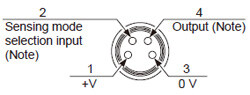
Connector pin position (pigtailed type)
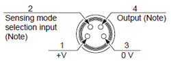
Note:The emitter of a thru-beam type does not incorporate output and output operation switching input.
PNP output type
I/O circuit diagrams
Notes:
1)The emitter of a thru-beam type does not incorporate output (black / 4) and output operation switching input (pink / 2).
2)Be able to select either Light-ON or Dark-ON by wiring the output operation switching input (pink / 2) as shown in the following table.
Type | Light-ON | Dark-ON |
|---|---|---|
| Thru-beam, Retroreflective | Connect to 0 V | Connect to + V or, Open |
| Spot reflective / Convergent reflective | Connect to + V or, Open | Connect to 0 V |
* Insulate the output operation switching input wire (pink / 2) when leaving it open.
3)When connecting the mating cable to the pigtailed type, color code of wire is “white”.
Connector pin position (pigtailed type)
Note:The emitter of a thru-beam type does not incorporate output and output operation switching input.
Sensing characteristics
*TYPICAL
EX-L211□
Thru-beam type
Parallel deviation
Angular deviation
EX-L212□
Thru-beam type
Parallel deviation
Angular deviation
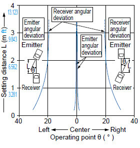
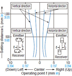
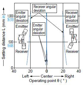
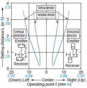
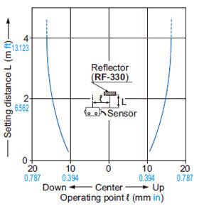
EX-L291□
Retroreflective type
Parallel deviations
• Horizontal direction
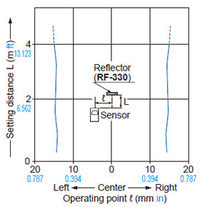
• Vertical direction
Angular deviation
• Horizontal direction
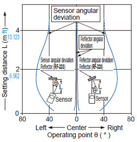
• Vertical direction
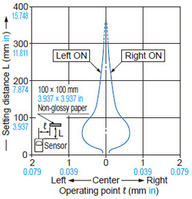
EX-L221□
Spot reflective type
Sensing field
Correlation between sensing object size and sensing range
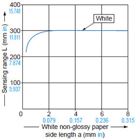
As the sensing object size becomes smaller than the standard size (white non-glossy paper 100 × 100 mm 3.937 × 3.937 in), the sensing range shortens, as shown in the left graph.
(For plotting the left graph, the sensitivity has been set such that a 100 × 100 mm 3.937 × 3.937 in white non-glossy paper is just detectable at a distance of 300 mm 11.811 in.)
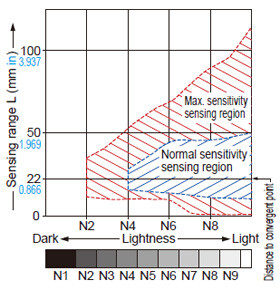
Correlation between lightness and sensing range
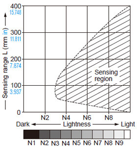
The sensing region (typical) is represented by oblique lines in the left figure. However, the sensitivity should be set with an enough margin because of slight variation in products.
(The graph is drawn for the maximum sensitirity setting.)
(Lightness shown on the left may differ slightly from the actual object condition.)
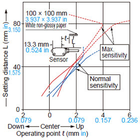
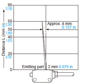
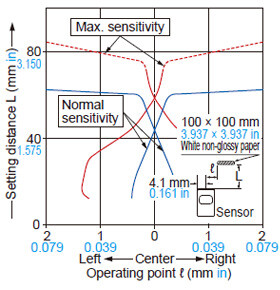
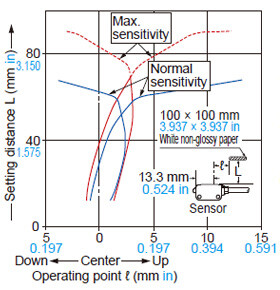
EX-L261□
Convergent reflective
Sensing fields
• Horizontal (left and right) direction
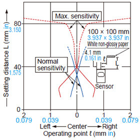
• Vertical (up and down) direction
Emitted beam
Correlation between lightness and sensing range
The sensing region (typical) is represented by oblique lines in the left figure. However, the sensitivity should be set with enough margin because of slight variation in products.
Lightness shown on the left may differ slightly from the actual object condition.
Correlation between material and sensing range (face-to-face)
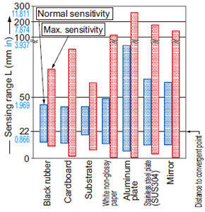
The bars in the graph indicate the sensing range (typical) for the respective material. However, there is a slight variation in the sensing range depending on the product.
Further, if there is a reflective object (conveyor, etc.) in the background of the sensing object, since it affects the sensing, separate it by more than twice the sensing range shown in the left graph, or adjust the sensitivity adjuster.
Make sure to confirm detection with an actual sensor.
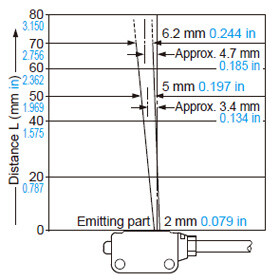
EX-L262□
Convergent reflective
Sensing fields
• Horizontal (left and right) direction
• Vertical (up and down) direction
Emitted beam
Correlation between lightness and sensing range
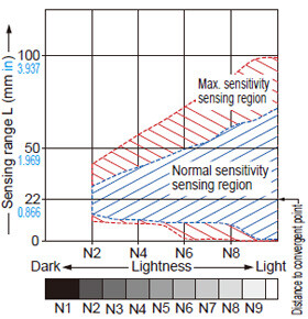
The sensing region (typical) is represented by oblique lines in the left figure. However, the sensitivity should be set with enough margin because of slight variation in products.
(Lightness shown on the left may differ slightly from the actual object condition.)
Correlation between material and sensing range (face-to-face)
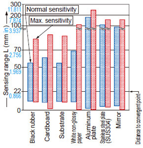
The bars in the graph indicate the sensing range (typical) for the respective material. However, there is a slight variation in the sensing range depending on the product.
Further, if there is a reflective object (conveyor, etc.) in the background of the sensing object, since it affects the sensing, separate it by more than twice the sensing range shown in the left graph, or adjust the sensitivity adjuster.
Make sure to confirm detection with an actual sensor.
- This product is classified as a Class 1 Laser Product in IEC / EN / JIS / GB / KS standards and in FDA* regulations. Do not look at the laser beam through optical system such as a lens.
- The following label is attached to the cable. Handle the product according to the instruction given on the warning label

*This product complies with the FDA regulations (FDA 21 CFR 1040.10 and 1040.11) in accordance with FDA Laser Notice No. 56, except for complying with IEC 60825-1 Ed. 3.
Safety standards for laser beam products
For the purpose of preventing any injury which may occur to the user by the use of the laser product in advance, the following standards have been established by the IEC Standards, EN Standards, JIS Standards, GB Standards, KS Standards and FDA Regulations.
IEC ... IEC 60825-1: 2014
EN ...EN 60825-1: 2014 / A11: 2021
JIS ...JIS C 6802: 2014
GB ...GB 7247.1-2012
KS ...KS C IEC 60825-1: 2014
FDA ...PART 1040.10, 1040.11 (Laser Notice No.56 applied)
These standards classifies laser products according to the level of hazard and provide the safety measures for respective classes.
Based on the above standards, EX-L200 series is classified as a Class 1 laser product.
| Classification | Description |
|---|---|
| Class 1 | Lasers that are safe under reasonably foreseeable conditions of operation, including the use of optical instruments for intrabeam viewing. |
Note: When an unexpected failure occurs, dangerous radiation may be generated. Therefore, pay special attention to safety.
Safe use of laser products
- For the purpose of preventing users from suffering injuries by laser products, each standard stipulates (Safety of laser products).Kindly check the standards before use.
Mounting
Note:The mounting direction of the mounting plate is fixed. Install in a way so that the bending shape is facing the sensor side.
- When mounting this sensor, use a mounting plate (MS-EXL2-2, MS-EXL2-3). Without using the mounting plate, beam misalignment may occur. Also, install the mounting plate in between the sensor and the mounting surface.
- The tightening torque should be 0.5 N·m or less.
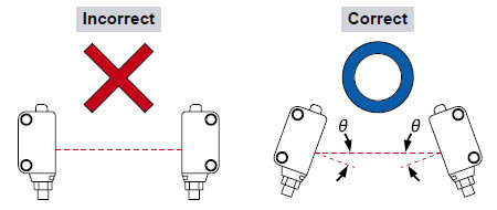
Automatic interference prevention function
- Spot reflective type sensor incorporate this function.
Up to two sets of sensor can be mounted closely.
(Thru-beam type sensor does not have this function.)
2 sensor heads can be mounted adjacently.
Note:If two spot reflective type sensor are mounted facing each other, they should be angled so as not to receive the beam from the opposing sensor or to detect its front face.
Others
- Do not use during the initial transient time (approx. 50ms) after the power supply is switched ON.
- In case the load and this sensor are connected to different power supplies, be sure to turn ON the power from the sensor.
- The cable may break by applying excess stress in low temperature.
- Do not allow any water, oil fingerprints, etc., which may refract light, or dust, dirt, etc., which may block light, to stick to the emitting / receiving surfaces of the sensor head. In case they are present, wipe them with a clean, soft cloth or lens paper. Do not use this sensor in places having excessive vapor, dust, etc., or where it may come in contact with corrosive gas.
- Take care that the sensor does not come in direct contact with oil, grease, organic solvents, such as, thinner etc., or strong acid, and alkaline.
- Make sure that the power is OFF while cleaning the emitting / receiving windows of the sensor head.
- This device is using a laser which has high directional quality. Therefore the beam possibly be out of alignment by the mounting condition of this device or distortion of housing etc. Make sure to adjust the beam axe alignment before use.