Basic Information
Reduction of the data analysis burden - one small step towards IoT.
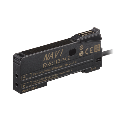
IO-Link Compatible, Self-Monitoring Type


Features
Reduction of the data analysis burdenone small step towards IoT.
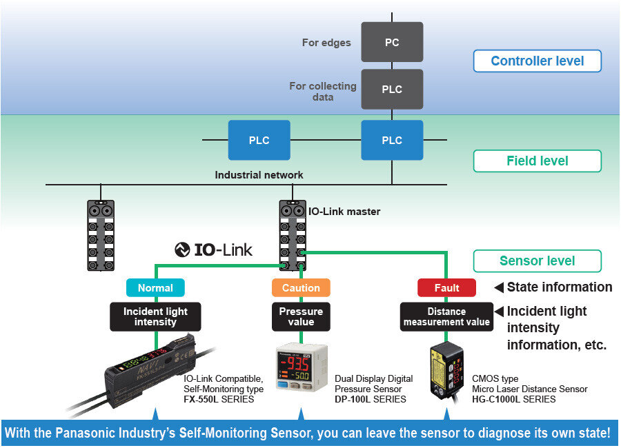
IO-Link compatible Collecting sensor level data
Field data collected and accumulated for “preventive maintenance” and “operation monitoring”.
An analysis of such field data requires high-level know-how and time, causing a burden to people responsible for the production site management.
The Self-Monitoring Sensor manufactured by Panasonic Industry is capable of reporting sensor data and its own state to the host device through the I/O Link master.
With the Self-Monitoring Sensor, you can immediately judge the state of the sensor and easily identify the cause of failure. Thus, this sensor contributes to the reduction of the burden experienced by the client in collecting and analyzing data.
Incorporated self-monitoring function
With the Panasonic Industry's Self-Monitoring Sensor,you can get high-level solutions!
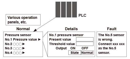
Problems are solved by the Self-monitoring function.
| Status | Judgement of the state | ||
|---|---|---|---|
| Normal | Operation is normal. | ||
| Notification | Check the settings. Detected state is faulty. | * Recover to the normal state through checking installation and settings. Reduction in the incident light intensity | |
| Caution | Getting close to the end of service life. Reached the state where the device should be replaced. | * Limitation in the writing frequency into the memory or in the operation hours, etc. | |
| Fault | Short-circuited or broken. Reached the state where it is impossible to control as a device. | * Short-circuited output, damaged EEPROM, etc. | |
*
By creating a program with a PLC, etc., the "State" of the self-monitoring sensor can be grasped.
Software are available for download. *Membership registration is required to access/download this data.
>>Go to Data download.
Easy use of IoT
“Predictive maintenance” can be easily achieved through monitoring the state of the Self-Monitoring Sensor.
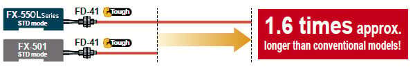
Emission power: 3 times the conventional ratio, Sensing range: 1.6 times max.!
Largely improved stability and ease of use due to higher emission power and broader utility!
This digital fiber sensor realizes longer sensing range than expected even with thin fibers.
| Fiber | Sensing range(STD mode) | Rate of increase in sensing range | |
|---|---|---|---|
| FX-550LSERIES | FX-501 | ||
| FT-31 | 480mm18.898 in | 315mm 12.402 in | 152% |
| FT-42 | 1,470mm57.874 in | 1,130mm 44.488 in | 130% |
| FD-41 | 200mm7.874 in | 125mm 4.921 in | 160% |
| FD-61 | 620mm24.409 in | 450mm 17.717 in | 138% |
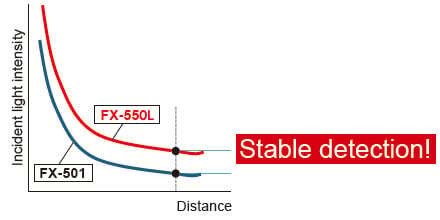
When the hysteresis is the same, the higher incident light intensity results in more stable detection.
When the hysteresis is the same, the higher incident light intensity results in more stable detection.
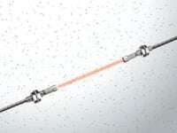
Easy adjustment of beam axis
Thanks to the high emission power, a slight deviation of beam axis causes no problem. It is ideal for use in dusty areas* or for detection through an extremely small slit.
* Need to confirm proper operation in installed condition.
Equipped with a mode to minimize the effect of ambient light
When setting to activate the environment resistance mode in the emission frequency setting, the ambient illuminance for LED lights becomes about 2.5 times higher than that in the normal mode. This reduces erroneous detections caused by LED lights.

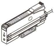
Simplified functions for improved operation ease
The FX-500 series and newer models are equipped with only basic functions for improved ease of use. No matter which model you select, they are all easy to use.
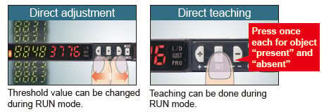
MODE NAVI + Direct setting
MODE NAVI uses three indicators and a dual display to show the amplifier’s basic operations. The current operation mode can be confirmed at a glance, so even a first-time user can easily operate the amplifier.
■NAVI display (lights off during RUN mode)
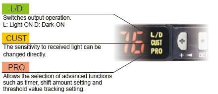
■Direct setting
Note:When connecting to upper communication unit, SC-GU3 series/SC-GU1-485, please select FX-500 series.
■List of functions in PRO mode
| PRO 1 | Response time setting, timer setting, shift amount setting |
|---|---|
| PRO 2 | Teaching lock setting, digital display item setting, digital display turning setting, Eco setting |
| PRO 3 | Display adjustment setting, reset setting, emission frequency setting, threshold value tracking setting |
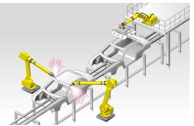
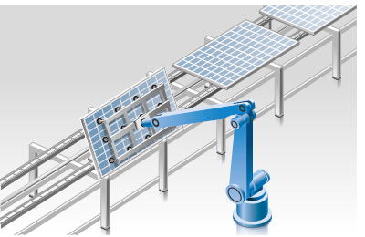
Applications
IoT Examples at FA Sites
Before the introduction of Self-Monitoring Sensors
Preventive maintenance
●We want to avoid production line stoppage that might occur due to unexpected sensor failure.
Line stoppage hours × (manufacturing unit cost / hour) = Loss
●We want to minimize the production line down time to almost zero.
Problems
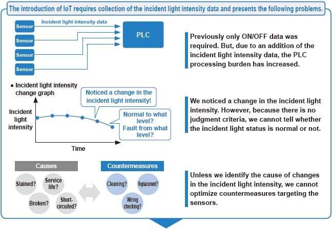
◆The amount of data to be collected is large and this may lower the PLC processing capacity.
◆The burden of data analysis is large.
◆Resetting the replaced sensors is troublesome.

After the introduction of Self‑Monitoring Sensors
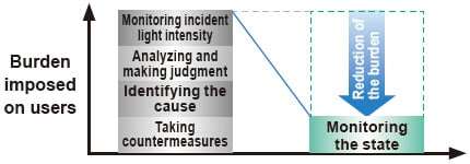
From preventive maintenance to predictive maintenance
Leave the sensor diagnosis to the sensor itself.
●All you need to do is to monitor the sensor state.
●PLC can be used exclusively for controlling devices.
●Possible to check detail information at a desired timing.
Leave the resetting for replaced sensors to the higher-level master
●Automatically written from the connected master.
●Possible not only to save time but also to prevent human errors.
IoT Examples at FA Sites 02
Before the introduction of Self-Monitoring Sensors
Remote controlling
and batch settings
●We want to place sensors close to sensing points as much as possible.
However, it is often difficult to make settings, particularly when there are many sensors to install.
●We want to send predetermined parameter values in a batch file for a repeater, etc.
●We want to confirm that required sensors are properly connected at the startup of the system.

Problems
◆It takes time to set sensors.
◆We want to avoid mistakes in setting sensors or wiring.

After the introduction of Self‑Monitoring Sensors
Fully utilize the advantages of the IO‑Link output.
●Possible to read or write set values through external
interface.
●Possible to set multiple sensors in a batch process.
●Possible to save the set parameters in an external medium.
●Possible to recognize and discriminate individual information.
Order guide
Amplifiers
| Type | Appearance | Model No. | Emitting element | Control output |
|---|---|---|---|---|
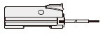
| Discrete wire type |
| FX-551L3-P-C2 | Red LED | PNP open-collector transistor |
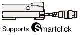
| M12 connector type |
| FX-551L3-P-J |
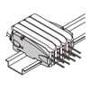
End plates
End plates are not supplied with the amplifier. Please order them separately when the amplifiers are mounted in cascade.
| Appearance | Model No. | Description |
|---|---|---|
| MS-DIN-E | When amplifiers are mounted in cascade, or when an amplifier moves depending on the way it is installed on a DIN rail, these end plates clamp amplifiers into place on both sides. Make sure to use end plates when cascading multiple amplifiers together. Two pcs. per set |
Option
| Designation | Model No. | Description |
|---|---|---|
| Amplifier mounting bracket | MS-DIN-2 | Mounting bracket for amplifier |
MS-DIN-2
Recommended extension cables for M12 connector type
Manufactured by OMRON Corporation
Extension cable with connectors on both ends XS5W series
※Contact the manufacturer for details of the recommended products.
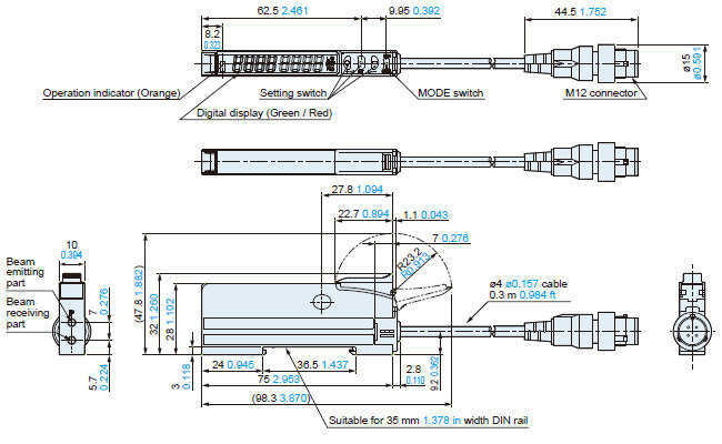
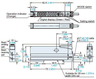
Dimensions
- Unit: mm in
FX-551L3-P-J
Amplifier
FX-551L3-P-C2
Amplifier
MS-DIN-2
Amplifier mounting bracket (Optional)
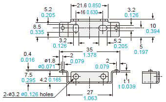
Material: Cold rolled carbon steel (SPCC) (Uni-chrome plated)
MS-DIN-E
End plate (Optional)
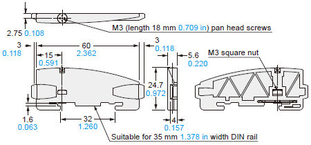
Material: Polycarbonate
I/O Circuit and Wiring diagrams
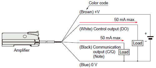
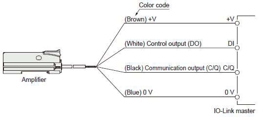
FX-551L3-P-C2
Discrete wire type
<When using as an ordinary sensor>
<When connecting to the IO-Link master>
Note:
When the sensor is used as an ordinary sensor, the communication output (C/Q) provides the same output operation as the control output (DO).
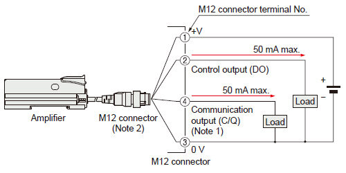
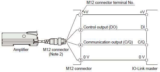
FX-551L3-P-J
M12 connector type
<When using as an ordinary sensor>
<When connecting to the IO-Link master>
Notes:
1)When the sensor is used as an ordinary sensor, the communication output (C/Q) provides the same output operation as the control output (DO).
2)When wiring with the discrete wire or extending the cable from the M12 connector, separately prepare commercially available M12 connector cable.
M12 connector terminal arrangement diagram
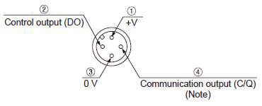
| Terminal No. | Designation |
|---|---|
| ① | +V |
| ② | Control output (DO) |
| ③ | 0V |
| ④ | Communication output (C/Q) (Note) |
Note:When the sensor is used as an ordinary sensor, the communication output (C/Q) provides the same output operation as the control output (DO).