Basic Information
From wide areas to narrow spaces, full support for both safety and productivity!


CE :Machinery Directive, EMC Directive
UKCA :Machinery Regulations, EMC Regulations


-
The control category differs depending on the configuration and wiring of the external circuit.
Features
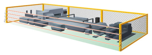
Long sensing range of up to 15 m 49.213 ft [Sensor head]
Secures safety of large facilities where installation of guardian fence is difficult.
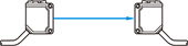
Series connection of sensors and interference prevention [Sensor head]
The numbers of sensor heads and controllers can be freely adjusted to meet the heights and the required numbers of the protection area.
![Series connection of sensors and interference prevention [Sensor head]](https://tp.industry.panasonic.com/hubfs/pid-corp/products/fasys/sensor/safety/st4/images/pic03.jpg)
Beam axis alignment and operation confirmation [Sensor head]
The beam interruption indicator is incorporated in both the emitter and receiver. This indicator can be used not only for operation confirmation but also for beam axis alignment. Moreover, the stability indicator indicates if the incident light intensity exceeds 150 % in stable operation.
![Beam axis alignment and operation confirmation [Sensor head]](https://tp.industry.panasonic.com/hubfs/pid-corp/products/fasys/sensor/safety/st4/images/pic04.jpg)
Supports beam axis alignment at startup and quick restoration in case of trouble [High-functional type ST4-C12EX]
Light received condition of the sensor heads in series connection can be confirmed by the high-functional controller ST4-C12EX.
In addition, any abnormal sensors during lockout can be identified.
![Supports beam axis alignment at startup and quick restoration in case of trouble [High-functional type ST4-C12EX]](https://tp.industry.panasonic.com/hubfs/pid-corp/products/fasys/sensor/safety/st4/images/pic05.jpg)
In small openings where safety light curtains cannot be installed
Ensures safety in small openings that are often missed.
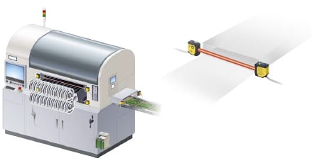
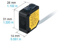
Compact sensor head saves space
The Type 4 long sensing range type has a compact size that is equivalent to those of general-purpose photoelectric sensors.
Industry standard mounting pitch [Sensor head]
Having the same mounting pitch as those of general-purpose photoelectric sensors makes model switchovers easy.
![Industry standard mounting pitch [Sensor head]](https://tp.industry.panasonic.com/hubfs/pid-corp/products/fasys/sensor/safety/st4/images/pic08.jpg)
Waterproof IP67
Conforming to IP67 rating, the sensor heads can be used safely even at lines where water splashes during washing.
![Protection structure IP67 [Sensor head]](https://tp.industry.panasonic.com/hubfs/pid-corp/products/fasys/sensor/safety/st4/images/pic09.jpg)
Control of interferences to surrounding sensors [Sensor head]
The emission amount adjuster can be used to reduce the emission to control any interference to the surrounding sensors.
![Control of interferences to surrounding sensors [Sensor head]](https://tp.industry.panasonic.com/hubfs/pid-corp/products/fasys/sensor/safety/st4/images/pic10.jpg)
Supports both PNP and NPN polarities [Controller]
A single unit can be used for PNP / NPN output switching, reducing the number of parts that need to be registered.
![Supports both PNP and NPN polarities [Controller]](https://tp.industry.panasonic.com/hubfs/pid-corp/products/fasys/sensor/safety/st4/images/pic11.jpg)
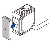
Easy connector connection [Controller]
Connecting to the sensor head is done using connector connections, which shortens setup and replacement time.
![Easy connector connection [Controller]](https://tp.industry.panasonic.com/hubfs/pid-corp/products/fasys/sensor/safety/st4/images/pic12.jpg)
Easy setup requiring no torque control
A spring method is used for the terminal blocks. There is no need to control tightening torques for these terminal blocks.
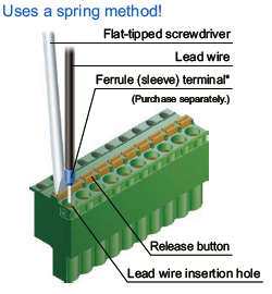
Connection is possible with a single wire or coil wires.
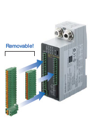
Removal terminal blocks reduce maintenance time
The work required for reconnecting wiring during maintenance is reduced.
Semiconductor output reduces running costs! [Controller]
Semiconductor output is used for control output. This means there is no need to periodically replace safety relays.
![Semiconductor output reduces running costs! [Controller]](https://tp.industry.panasonic.com/hubfs/pid-corp/products/fasys/sensor/safety/st4/images/pic15.jpg)
Error details can be understood at a glance! [High-functional type ST4-C12EX]
If a problem should occur, the control output is switched OFF, and the details of the error appear on the digital display.
![Error details can be understood at a glance! [High-functional type ST4-C12EX]](https://tp.industry.panasonic.com/hubfs/pid-corp/products/fasys/sensor/safety/st4/images/pic16.jpg)
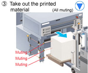
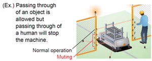
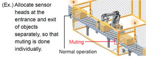
Three patterns of muting control function for greater safety with no loss in productivity [High-functional type ST4-C12EX]
Sensor heads, muting sensors, and muting lamps connect directly to the controller, so that muting control circuits can be built easily.
![Three patterns of muting control function for greater safety with no loss in productivity [High-functional type ST4-C12EX]](https://tp.industry.panasonic.com/hubfs/pid-corp/products/fasys/sensor/safety/st4/images/pic17.jpg)
![Three patterns of muting control function for greater safety with no loss in productivity [High-functional type ST4-C12EX]](https://tp.industry.panasonic.com/hubfs/pid-corp/products/fasys/sensor/safety/st4/images/pic18.jpg)
Muting pattern No.1 Compliant to international safety standard ISO 12643 for printing industry Muting area can be changed to suit the printing process. This is the optimal muting control for printing machines.
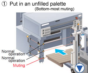
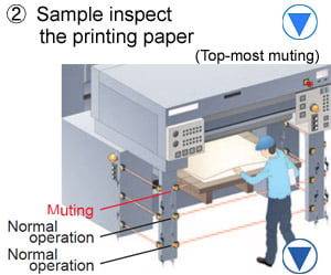
Muting pattern No.2
Set apart only the top-most sensor heads and perform muting control.
Muting pattern No.3
Divide the muting area into two.
Line restarts smoothly after being stopped while muting control was active <Override function> [High-functional type ST4-C12EX]
In case the sensor head has been interrupted by an object or in case there is an emergency stop before the muting conditions have been established, all the sensor heads will be temporarily deactivated following by a smooth restart.
![Line restarts smoothly after being stopped while muting control was active <Override function> [High-functional type ST4-C12EX]](https://tp.industry.panasonic.com/hubfs/pid-corp/products/fasys/sensor/safety/st4/images/pic24.jpg)
Informs all kinds of operation conditions [High-functional type ST4-C12EX]
In case the muting lamp that is connected to the controller breaks, an alarm will go off. Also, auxiliary outputs that link to the muting function, override function, and control outputs (OSSD) are incorporated.
| Auxiliary outputs | Function | Operation |
|---|---|---|
| Auxiliary output 1 | Muting output | ON when muting function is invalid |
| Auxiliary output 2 | Override output | ON when override function is invalid |
| Auxiliary output 3 | Blown lamp output | ON when muting lamp is in normal condition |
| Auxiliary output 4 | Monitor output | ON when control output is OFF |


Order guide
Sensor heads
Always use the sensor head and the controller together as a set.
| Type | Appearance | Operating range (Note 1) | Model No. (Note 2) | |
|---|---|---|---|---|
| Cable length 0.2 m 0.656 ft |
| 0.1 to 15 m 0.328 to 49.231 ft | ST4-A1-J02 | |
| With emission amount adjuster | ST4-A1-J02V | |||
| Cable length 1 m 3.281 ft | ST4-A1-J1 | |||
| With emission amount adjuster | ST4-A1-J1V | |||
Note 1 : The "operating range" is the possible setting distance between the emitter and the receiver.
Note 2 : The model No. with suffix "E" shown on the label affixed to the product is the emitter, "D" shown on the label is the receiver.
Controllers
Always use the sensor head and the controller together as a set.
Option
| Designation | Model No. | Description | ||
|---|---|---|---|---|
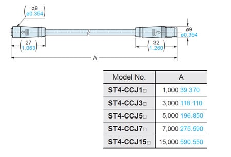
| Extension cable | ST4-CCJ1E | Cable length: 1 m 3.281 ft Net weight 55 g approx. (1 cable) | For emitter | Use as an extension for the ST4-A□. 5-wire shielded cable. One each for emitter and receiver Cable color: Gray (for emitter), Gray with black line (for receiver) Connector color: Gray (for emitter), Black (for receiver) Min. bending radius: R5 mm R0.197 in |
| ST4-CCJ1D | For receiver | |||
| ST4-CCJ3E | Cable length: 3 m 9.843 ft Net weight 130 g approx. (1 cable) | For emitter | ||
| ST4-CCJ3D | For receiver | |||
| ST4-CCJ5E | Cable length: 5 m 16.404 ft Net weight 200 g approx. (1 cable) | For emitter | ||
| ST4-CCJ5D | For receiver | |||
| ST4-CCJ7E | Cable length: 7 m 22.966 ft Net weight 270 g approx. (1 cable) | For emitter | ||
| ST4-CCJ7D | For receiver | |||
| ST4-CCJ15E | Cable length: 15 m 49.213 ft Net weight 540 g approx. (1 cable) | For emitter | ||
| ST4-CCJ15D | For receiver | |||
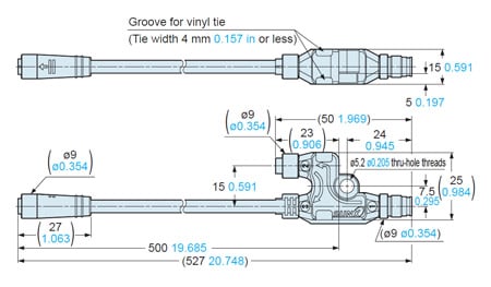
| Branch cable | ST4-CCJ05-WY | Cable length: 0.5 m 1.640 ft Net weight 80 g approx. (2 cables) | Use to connect ST4-A□ in series. 5-wire shielded cable. Two cables per set for emitter and receiver Cable color: Gray (for emitter), Gray with black line (for receiver) Connector color: Gray (for emitter), Black (for receiver) Min. bending radius: R5 mm R0.197 in | |
| Sensor head mounting bracket | MS-CX-1 | Foot angled mounting bracket. 2 different types for emitter and receiver required. | ||
| MS-ST4-3 | Back angled mounting bracket. 2 different types for emitter and receiver required. | |||
| MS-ST4-6 | Foot biangled mounting bracket. 2 different types for emitter and receiver required. | |||
| Round slit mask (Note) | OS-ST4-2 (Slit size ø2mm ø0.079 in) | Dampens the light to suppress interference with neighboring sensors. | Operating range Slit on one side: 3 m 9.843 ft Slit on both sides: 0.75 m 2.461 ft | |
| OS-ST4-3 (Slit size ø3mm ø0.118 in) | Operating range Slit on one side: 4.5 m 14.764 ft Slit on both sides: 1.5 m 4.921 ft | |||
Note : When the slit mask is installed, applicable sensing objects are opaque objects with a diameter of ø9 mm ø0.354 in or more.
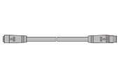
Extension cable
ST4-CCJ□
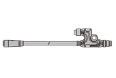
Branch cable
ST4-CCJ05-WY
Sensor mounting bracket
MS-CX-1
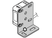
Two M3 (length 12 mm 0.472 in)screws with washers are attached.
MS-ST4-3
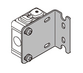
Two M3 (length 12 mm 0.472 in)screws with washers are attached.
MS-ST4-6
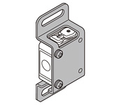
Two M3 (length 12 mm 0.472 in)screws with washers are attached.
Round slit mask
OS-ST4-2
OS-ST4-3
Dimensions
- Unit: mm in
ST4-A□
Sensor head
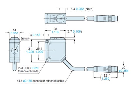
Note:It indicates the position of the emission amount adjuster on ST4-A□V.
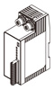
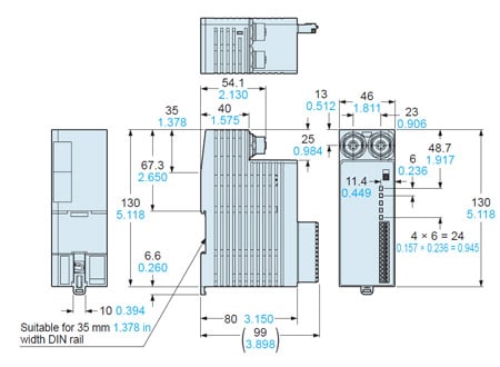
ST4-C11
Controller
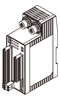
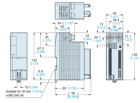
ST4-C12EX
Controller
ST4-CCJ□
Extension cable (Optional)
ST4-CCJ05-WY
Branch cable (Optional)
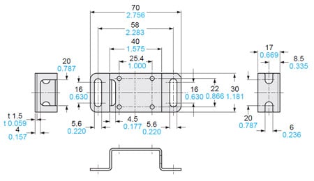
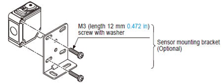
MS-CX-1
Sensor head mounting bracket (Optional)
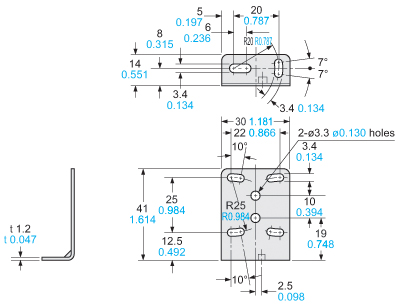
Material:
Stainless steel (SUS304)
Two M3 (length 12 mm 0.472 in) screws with washers are attached.
MS-ST4-3
Sensor head mounting bracket (Optional)
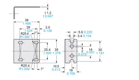
Material:
Stainless steel (SUS304)
Two M3 (length 12 mm 0.472 in) screws with washers are attached.
MS-ST4-6
Sensor head mounting bracket (Optional)
Material:
Stainless steel (SUS304)
Two M3 (length 12 mm 0.472 in) screws with washers are attached.
I/O Circuit and Wiring diagrams
ST4-C11
In case of PNP output
・Set the output polarity selection switch to the PNP side.
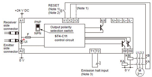
Notes:
1) The left diagram is when using manual reset. If automatic reset is used, disconnect the lead from X2 and connect it to X3. In this case, a reset (RESET) button is not needed.
2) Use a momentary-type switch as the reset (RESET) button.
3) Emission halt input is for stopping emission when open, and emitting when short-circuited. If not using the test button, short-circuit T1 and T2.
KA, KB: Force-guided relay or magnetic contactor
In case of NPN output
・Set the output polarity selection switch to the NPN side.
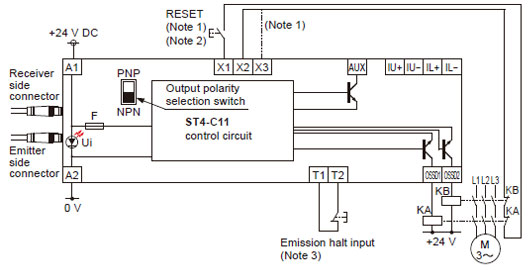
Notes:
1) The left diagram is when using manual reset. If automatic reset is used, disconnect the lead from X2 and connect it to X3. In this case, a reset (RESET) button is not needed.
2) Use a momentary-type switch as the reset (RESET) button.
3) Emission halt input is for stopping emission when open, and emitting when short-circuited. If not using the test button, short-circuit T1 and T2.
KA, KB: Force-guided relay or magnetic contactor
Terminal arrangement diagram
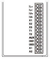
| Terminal | Description |
|---|---|
| IL+ | Interference prevention terminals For details, refer to "Interference prevention function" |
| IL- | |
| IU+ | Interference prevention terminals For details, refer to "Interference prevention function" |
| IU- | |
| X1 | Reset input terminals (When X1 and X2 are connected: manual reset, and when X1 and X3 are connected: auto reset) |
| X2 | |
| X3 | |
| T1 | Emission halt input terminals (Open: emission halt, Short-circuit: emission) |
| T2 | |
| AUX | Negative logic of the control outputs (OSSD1, OSSD2) |
| OSSD1 | Control outputs (OSSD1, OSSD2) |
| OSSD2 | |
| A1 | 24V DC |
| A2 | 0V |
ST4-C12EX
In case of PNP output
・Set the output polarity selection switch to the PNP side.
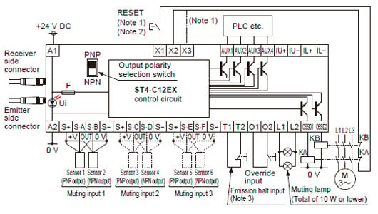
Notes:
1) The left diagram is when using manual reset. If automatic reset is used, disconnect the lead from X2 and connect it to X3. In this case, a reset (RESET) button is not needed.
2) Use a momentary-type switch as the reset (RESET) button.
3) Emission halt input is for stopping emission when open, and emitting when short-circuited. If not using the test button, short-circuit T1 and T2.
KA, KB: Force-guided relay or magnetic contactor
In case of NPN output
・Set the output polarity selection switch to the NPN side.
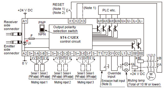
Notes:
1) The left diagram is when using manual reset. If automatic reset is used, disconnect the lead from X2 and connect it to X3. In this case, a reset (RESET) button is not needed.
2) Use a momentary-type switch as the reset (RESET) button.
3) Emission halt input is for stopping emission when open, and emitting when short-circuited. If not using the test button, short-circuit T1 and T2.
KA, KB: Force-guided relay or magnetic contactor
Terminal arrangement diagram
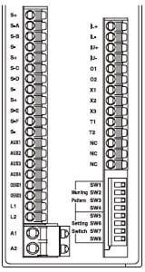
| Terminal | Description |
|---|---|
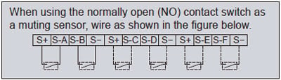
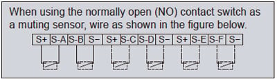
| S+ | Muting input power supply (24 V) |
| S-A | Muting input S-A [For NO (nomally open) contact or PNP output type sensor] |
| S-B | Muting input S-B [For NO (nomally open) contact or NPN output type sensor] |
| S- | Muting input power supply (0 V) |
| S+ | Muting input power supply (24 V) |
| S-C | Muting input S-C [For NO (nomally open) contact or PNP output type sensor] |
| S-D | Muting input S-D [For NO (nomally open) contact or NPN output type sensor] |
| S- | Muting input power supply (0 V) |
| S+ | Muting input power supply (24 V) |
| S-E | Muting input S-E [For NO (nomally open) contact or PNP output type sensor] |
| S-F | Muting input S-F [For NO (nomally open) contact or NPN output type sensor] |
| S- | Muting input power supply (0 V) |
| AUX1 | Auxiliary output 1 (muting function) |
| AUX2 | Auxiliary output 2 (override function) |
| AUX3 | Auxiliary output 3 (muting lamp shutoff) |
| AUX4 | Negative logic of the control outputs (OSSD1, OSSD2) |
| OSSD1 | Control outputs (OSSD1, OSSD2) |
| OSSD2 | |
| L1 | Muting lamp connecting terminal |
| L2 | |
| A1 | 24V DC |
| A2 | 0V |
| IL+ | Interference prevention terminals For details, refer to "Interference prevention function" |
| IL- | |
| IU+ | Interference prevention terminals For details, refer to "Interference prevention function" |
| IU- | |
| O1 | Override input terminals |
| O2 | |
| X1 | Reset input terminals (When X1 and X2 are connected: manual reset, and when X1 and X3 are connected: auto reset) |
| X2 | |
| X3 | |
| T1 | Emission halt input terminals (Open: emission halt, Short-circuit: emission) |
| T2 |
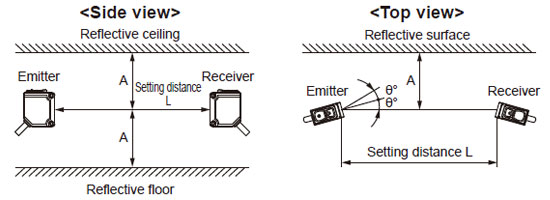
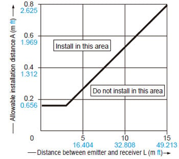
- Install this device at a distance of at least A (m) (given below) away from reflective surfaces such as metal walls, floors, ceilings, objects, covers, panels or glass surfaces.
| Distance between emitter and receiver (Setting distance L) | Allowable installation distance A |
|---|---|
| 0.1 to 3 m 0.328 to 9.843 ft | 0.16 m 0.525 ft |
| 3 to 15 m 9.843 to 49.213 ft | L/2×tan2θ=L×0.053(m) 0.174 (ft) ((θ=3°) |
Note:
The effective aperture angle for this device is ±2.5° (when L > 3 m 9.843 ft) as required by IEC 61496-2 / UL 61496-2. However, install this device away from reflective surfaces considering an effective aperture angle of ±3° to take care of beam misalignment, etc. during installation.
<Allowable installation distance between reflective surfaces and beam axis of receiver>
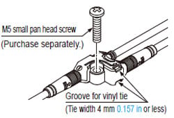
Mounting
- When mounting the sensor head, the tightening torque should be 0.5 N·m or less.
- When mounting ST4-CCJ05-WY, the tightening torque should be 0.7 N·m or less. Using a vinyl tie (width 4 mm 0.157 in or less) to fix the cable is also possible.