Basic Information
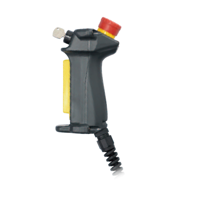
Compact, lightweight grip switches designed to fit comfortably in the hand


Features
This product line includes models with control units suited to a variety of applications.
The compact, light weight grip profile was designed based on human engineering considerations.
The compact profile fits the hand perfectly, ensuring comfortable operation. Thanks to its light weight design (SG-C1-21: approx. 140 g) and compact size, it is easy to hold even for individuals with small hands, and it can also be used in confined work locations.
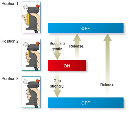
Reduced impact during extended operation
We reduced the impact during extended operation by lowering the holding load in position 2 (ON).
Pleasant, clear button operation
Tactile clicking feedback allows easy recognition of switch operation when shifting from position 1 (contact OFF) to position 2 (contact ON).
Order guide
Enable grip switch
| Contact configuration | Rubber boot material / Color | Wiring style | Model No. | |||||
|---|---|---|---|---|---|---|---|---|
| 3 position enabling switch | Push monitor switch | Additional control units | ||||||
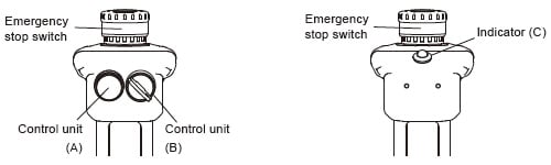
| Emergency stop switch | Control unit (A) | Control unit (B) | Indicator (green) (C) | |||||
| 2 contacts | With (1NC) | Without | Silicone rubber / (Yellow) (Note) | Solder terminal | SG-C1-21 | |||
| With (2NC) | Without | Without | SG-C1-21-E | |||||
| With | SG-C1-21-EG | |||||||
| Without | Momentary pushbutton switch (2c) | Momentary pushbutton switch (2c) | Without | SG-C1-21-MM | ||||
| With (2NC) | SG-C1-21-EMM | |||||||
| Key selector switch (2c) | SG-C1-21-EMK | |||||||
Note: Silicone rubber: Can be used in general factories. Remains flexible in cold temperatures. Suitable in applications with a wide operating temperature range.
Additional control unit layout
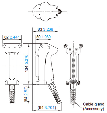
Dimensions
- Unit: mm in
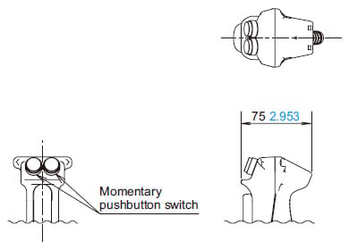
SG-C1-21
Enable grip switch
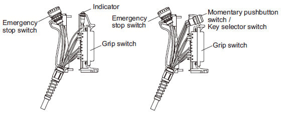
SG-C1-21-E
SG-C1-21-EG
Enable grip switch
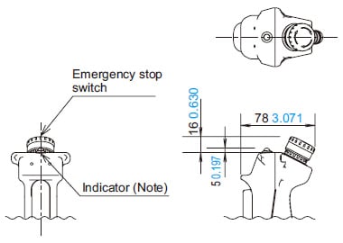
Note: Not included in SG-C1-21-E.
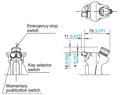
SG-C1-21-EMK
Enable grip switch
SG-C1-21-EMM
Enable grip switch
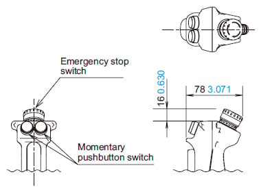
SG-C1-21-MM
Enable grip switch
- This device has been developed / produced for industrial use only.
- Use proper size wires to meet voltage and current requirements.
- Do not apply an excessive shock to the SG-C1 series.
- When wiring, prevent dust, water, or oil from entering the grip switch.
- If used in wet locations, this device must be used with cable suitable for wet locations.
- When multiple safety components are connected in series, the EN ISO 13849-1:2015 performance level will fall due to the deterioration in fault detection functionality.
- The suitability of control systems in which this product has been embedded must be verified in accordance with EN ISO 13849-2:2012.
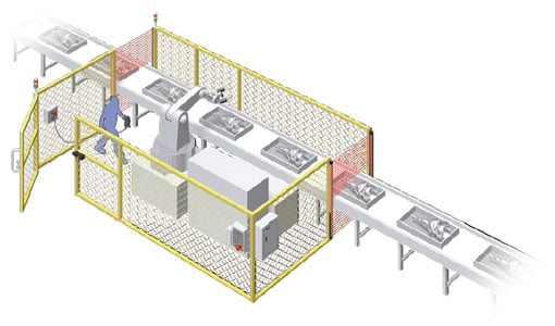
- SG-C1 series is a device used for enabling a machine (robot, etc.) when teaching the machine in a hazardous area manually.
Configure the enabling system so that the machine can operate when the switch is in position 2 and an additional "start" is pushed to initiate the operation. - In order to ensure safety of the control system, connect each pair of the contacts of the 3 position enabling switch (terminal No. NO1-C1 and NO2-C2) to a discrepancy detection circuit such as a safety relay module.
(ISO13849-1:2015) - The base and the plastic part of rubber boot frame are made of glass-reinforced ABS / PBT. The rubber boot is made of silicone rubber. The screw is made of iron. When cleaning the SG-C1 series, use a detergent compatible with the materials.
- As for momentary pushbutton switch and key selector switch of additional control unit, do not connect NO and NC contacts of a microswitch to different voltages or different power sources to prevent a dead short-circuit.
- Do not operate key selector switch of additional control unit without completely insertion of the key.
- The rubber boot may deteriorate depending on the operating environment and conditions.
Cable glands
- The product includes one cable gland. When purchasing replacements, ensure that they conform to the following dimensional range:
・Dimension diagram
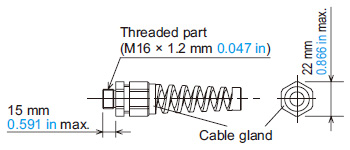
- Waterproofness: Use a cable gland that can maintain performance of IP67 or higher.
- Recommended connector: Model SKINTOP-BS-M16 × 1.5-B (manufactured by LAPP in Germany and imported by K.MECS Automation Inc.)
- Applicable cable diameter: Outer diameter of 4.5 to 10 mm 0.177 to 0.787 in
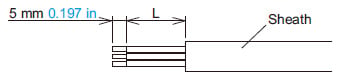
Wire length inside the grip switch
| Wire stripping length | Grip switch | Momentary pushbutton switch / Key selector switch | Emergency stop switch | Indicator | |||||||||
|---|---|---|---|---|---|---|---|---|---|---|---|---|---|
| NO1 | C1 | 31 | 32 | NO2 | C2 | C | NO | NC | 1 | 2 | + | - | |
| L(mm in) | 40 1.575 | 45 1.772 | 50 1.969 | 60 2.362 | 85 3.346 | 80 3.150 | 120 4.724 | 110 4.331 | 115 4.528 | ||||
<Wiring example>
Applicable wire size in terminal
・If direct-mounted:
0.5 mm2 (AWG20) or less
Wire SG-C1 series according to IEC60204-1
Wiring Instruction
Wiring
- Solder the terminal at 310 to 350 ℃ 590 to 662 ℉ within 3 seconds using a 60 W soldering iron.
Sn-Ag-Cu type is recommended when using lead free solder. - When soldering, do not touch the SG-C1-□ with the soldering iron. Also ensure that no tensile force is applied to the terminal.
Do not bend the terminal or apply excessive force to the terminal. - Use non-corrosive rosin flux.
- Because the terminal spacing is narrow, use protective tubes or heat shrinkable tubes to avoid burning of wire coating or short circuit.
- When using a stranded wire, make sure that adjoining terminals are not short-circuited with protruding core wires.
- Use copper wire 60 to 75 ℃ 140 to 167 ℉ only. (UL508)
- The wiring has to be installed according to GS-ET-22:2016, 4.2.6.
Recommended screw tightening torque
| Part being secured | Screw position | Screw tightening torque |
|---|---|---|
| For mounting rubber boot frame on the base (M4 screw × 4) | A | 1.1 to 1.3 N・m |
| Cable gland to Grip switch Screw | B | 2.7 to 3.3 N・m |
| Cable gland to cable gland | C | 2.7 to 3.3 N・m |
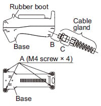
The B and C values in the above table reflect use of the recommended connectors listed above.
When using a cable gland other than the recommended model, check that part's tightening torque.