Discontinued Products

[Note]
The following applicable products and options are available continuously.
Extension cable
| Type | Model No. | Description | |||
|---|---|---|---|---|---|
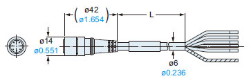
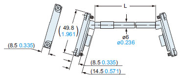
| 8-core cable | With connectors on both ends | For emitter | SFB-CCJ10E | Cable length: 10 m 32.808 ft Net weight: 580 g approx. (1 cable) | Used for cable extension or connecting to the SF-C11 control unit. One each for emitter and receiver Cable outer diameter: ø6 mm ø0.236 in Connector outer diameter: ø14 mm ø0.551 in max. Cable color: Gray (for emitter), Gray with black line (for receiver) Connector color: Gray (for emitter), Black (for receiver) The min. bending radius: R6 mm R0.236 in |
| For receiver | SFB-CCJ10D | Cable length: 10 m 32.808 ft Net weight: 600 g approx. (1 cable) | |||
Control units
| Designation | Model No. | Description | |
|---|---|---|---|
| Applicable cable | |||
| Connector connection type control unit | SF-C11 | SF2B-CB□ SFB-CCJ10□ | Use 8-core cable with connector to connect to the safety light curtain. Compatible with up to Control Category 4 (Control Category 2 when used together with the SF2B series). |
| Slim type control unit | SF-C13 | SF2B-CCB□ SFB-CC□ | Use a discrete wire cable to connect to the safety light curtain. Compatible with up to Control Category 4 (Control Category 2 when used together with the SF2B eries). |
Note: Refer to the exclusive control units SF-C10 series pages for the control units.
Corner mirror
| Applicable beam channels | Corner mirror | ||
|---|---|---|---|
| Hand | Arm / Foot | Model No. | Dimensions of effective reflective surface |
| 8 | 4 | RF-SFBH-8 | 173 × 72 mm 6.811 × 2.835 in |
| 12 | 6 | RF-SFBH-12 | 236 × 72 mm 9.291 × 2.835 in |
| 16 | 8 | RF-SFBH-16 | 316 × 72 mm 12.441 × 2.835 in |
| 20 | 10 | RF-SFBH-20 | 396 × 72 mm 15.591 × 2.835 in |
| 24 | 12 | RF-SFBH-24 | 476 × 72 mm 18.740 × 2.835 in |
| 28 | 14 | RF-SFBH-28 | 556 × 72 mm 21.890 × 2.835 in |
| 32 | 16 | RF-SFBH-32 | 636 × 72 mm 25.039 × 2.835 in |
| 36 | 18 | RF-SFBH-36 | 716 × 72 mm 28.190 × 2.835 in |
| 40 | 20 | RF-SFBH-40 | 796 × 72 mm 31.339 × 2.835 in |
| 48 | 24 | RF-SFBH-48 | 956 × 72 mm 37.638 × 2.835 in |
| 56 | 28 | RF-SFBH-56 | 1,116 × 72 mm 43.937 × 2.835 in |
| 64 | 32 | RF-SFBH-64 | 1,276 × 72 mm 50.236 × 2.835 in |
| 72 | 36 | RF-SFBH-72 | 1,436 × 72 mm 56.535 × 2.835 in |
| 80 | 40 | RF-SFBH-80 | 1,596 × 72 mm 62.835 × 2.835 in |
| 88 | 44 | RF-SFBH-88 | 1,756 × 72 mm 69.134 × 2.835 in |
| 96 | 48 | RF-SFBH-96 | 1,916 × 72 mm 75.433 × 2.835 in |
Note:The model Nos. given above denote a single unit, not a pair of units. 2 units are required for use in mounting to the emitter / receiver. (Except for corner mirror)
| Designation | Model No. | Description |
|---|---|---|
| Large display unit for safety light curtain | SF-IND-2 | With the auxiliary output of the safety light curtain, the operation is easily observable from various directions. |
Recommended safety relay
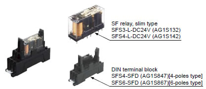
SF relay, slim type
SF series
Note:Please contactour sales officefor details on the recommended products.
| Type | With LED indicator | |
|---|---|---|
| Model No. | SFS3-L-DC24V | SFS4-L-DC24V |
| Part No. | AG1S132 | AG1S142 |
| Contact arrangement | 3a1b | 4a2b |
| Rated nominal switching capacity | 6A/250V AC、6A/30V DC | |
| Min. switching capacity | 1mA/5V DC | |
| Coil rating | 15mA/24V DC | 20.8mA/24V DC |
| Rated power consumption | 360mW | 500mW |
| Operation time | 20ms or less | |
| Release time | 20ms or less | |
| Ambient temperature | -40 to +85 ℃ -40 to + 185 ℉ (Humidity: 5 to 85 % RH) | |
| Applicable certifications | UL/c-UL, TÜV, Korea S-mark | |
Dimensions
- Unit: mm in
SF2B-□
SF2B-□SL
Safety light curtain, Sub-sensor for series connection only
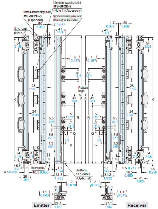
Assembly dimensions
Mounting drawing for the safety light curtains using the standard mounting brackets MS-SF2B-1 (optional) and the intermediate supporting brackets MS-SF2B-2(accessory for safety light curtain).
<Rear mounting>
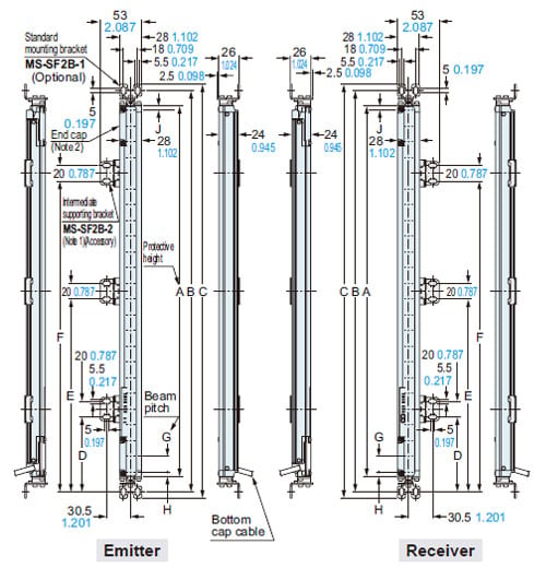
<Side mounting>
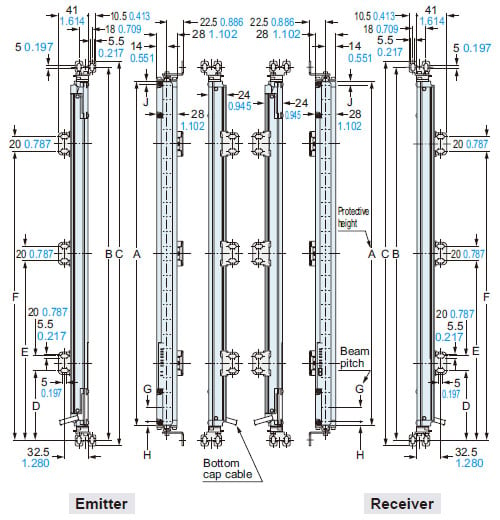
Notes:
1) The MS-SF2B-2 intermediate supporting bracket is provided as an accessory with this product. The number of accessories provided varies depending on the product.
2) An end cap (connector for series connection) is not provided for the SF2B-H8(SL)(-□) and SF2B-A4(SL)(-□).
| Model No. | A | B | C | D | E | F | |
|---|---|---|---|---|---|---|---|
| SF2B-H8(SL)(-□) | SF2B-A4(SL)(-□) | 168 6.614 | 207 8.150 | 223 8.780 | - | - | - |
| SF2B-H12(SL)(-□) | SF2B-A6(SL)(-□) | 232 9.134 | 270 10.630 | 286 11.260 | - | - | - |
| SF2B-H16(SL)(-□) | SF2B-A8(SL)(-□) | 312 12.283 | 350 13.780 | 366 14.409 | - | - | - |
| SF2B-H20(SL)(-□) | SF2B-A10(SL)(-□) | 392 15.433 | 430 16.929 | 446 17.559 | - | - | - |
| SF2B-H24(SL)(-□) | SF2B-A12(SL)(-□) | 472 18.583 | 510 20.079 | 526 20.709 | - | - | - |
| SF2B-H28(SL)(-□) | SF2B-A14(SL)(-□) | 552 21.732 | 590 23.228 | 606 23.858 | - | - | - |
| SF2B-H32(SL)(-□) | SF2B-A16(SL)(-□) | 632 24.882 | 670 26.378 | 686 27.008 | - | - | - |
| SF2B-H36(SL)(-□) | SF2B-A18(SL)(-□) | 712 28.031 | 750 29.528 | 766 30.157 | - | - | - |
| SF2B-H40(SL)(-□) | SF2B-A20(SL)(-□) | 792 31.181 | 830 32.677 | 846 33.307 | 390 15.354 | - | - |
| SF2B-H48(SL)(-□) | SF2B-A24(SL)(-□) | 952 37.480 | 990 38.976 | 1,006 39.606 | 470 18.504 | - | - |
| SF2B-H56(SL)(-□) | SF2B-A28(SL)(-□) | 1,112 43.779 | 1,150 45.276 | 1,166 45.905 | 550 21.654 | - | - |
| SF2B-H64(SL)(-□) | SF2B-A32(SL)(-□) | 1,272 50.079 | 1,310 51.575 | 1,326 52.205 | 418 16.457 | 842 33.150 | - |
| SF2B-H72(SL)(-□) | SF2B-A36(SL)(-□) | 1,432 56.378 | 1,470 57.874 | 1,486 58.504 | 472 18.583 | 948 37.323 | - |
| SF2B-H80(SL)(-□) | SF2B-A40(SL)(-□) | 1,592 62.677 | 1,630 64.173 | 1,646 64.803 | 525 20.669 | 1,055 41.535 | - |
| SF2B-H88(SL)(-□) | SF2B-A44(SL)(-□) | 1,752 68.976 | 1,790 70.472 | 1,806 71.102 | 433 17.047 | 870 34.252 | 1,308 51.496 |
| SF2B-H96(SL)(-□) | SF2B-A48(SL)(-□) | 1,912 75.275 | 1,950 76.772 | 1,966 77.401 | 473 18.622 | 950 37.402 | 1,428 56.220 |
| Model No. | G | H | J(Note) |
|---|---|---|---|
| SF2B-H□ | 20 0.787 | 6 0.236 | 6 0.236 |
| SF2B-A□ | 40 1.575 | 26 1.024 | 6 0.236 |
Note:The distance between the tip of the safety light curtain and the last beam axis of the SF2B-H8(SL)(-□) and SF2B-A4(SL)(-□) is 22 mm 0.866 in.
SF2B-□
SF2B-□SL
Safety light curtain, Sub-sensor for series connection only
Assembly dimensions
Mounting drawing for the safety light curtains using the dead zoneless mounting brackets MS-SF2B-3 (optional) and the intermediate supporting brackets MS-SF2B-2(accessory for safety light curtain).
<Rear mounting>
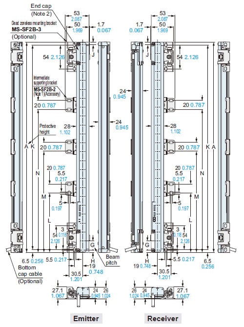
<Side mounting>
Notes:
1) The MS-SF2B-2 intermediate supporting bracket is provided as an accessory with this product. The number of accessories provided varies depending on the product.
2) An end cap (connector for series connection) is not provided for the SF2B-H8(SL)(-□) and SF2B-A4(SL)(-□).
| Model No. | A | K | L | M | N | P | Q | R | |
|---|---|---|---|---|---|---|---|---|---|
| SF2B-H8(SL)(-□) | SF2B-A4(SL)(-□) | 168 6.614 | 155 6.102 | - | - | - | - | - | - |
| SF2B-H12(SL)(-□) | SF2B-A6(SL)(-□) | 232 9.134 | 219 8.622 | - | - | - | - | - | - |
| SF2B-H16(SL)(-□) | SF2B-A8(SL)(-□) | 312 12.283 | 299 11.772 | - | - | - | - | - | - |
| SF2B-H20(SL)(-□) | SF2B-A10(SL)(-□) | 392 15.433 | 379 14.921 | - | - | - | - | - | - |
| SF2B-H24(SL)(-□) | SF2B-A12(SL)(-□) | 472 18.583 | 459 18.071 | - | - | - | - | - | - |
| SF2B-H28(SL)(-□) | SF2B-A14(SL)(-□) | 552 21.732 | 539 21.221 | - | - | - | - | - | - |
| SF2B-H32(SL)(-□) | SF2B-A16(SL)(-□) | 632 24.882 | 619 24.370 | - | - | - | - | - | - |
| SF2B-H36(SL)(-□) | SF2B-A18(SL)(-□) | 712 28.031 | 699 27.520 | - | - | - | - | - | - |
| SF2B-H40(SL)(-□) | SF2B-A20(SL)(-□) | 792 31.181 | 779 30.669 | 390 15.354 | - | - | 379.5 14.941 | - | - |
| SF2B-H48(SL)(-□) | SF2B-A24(SL)(-□) | 952 37.480 | 939 36.969 | 470 18.504 | - | - | 459.5 18.091 | - | - |
| SF2B-H56(SL)(-□) | SF2B-A28(SL)(-□) | 1,112 43.779 | 1,099 43.268 | 550 21.654 | - | - | 539.5 21.240 | - | - |
| SF2B-H64(SL)(-□) | SF2B-A32(SL)(-□) | 1,272 50.079 | 1,259 49.567 | 418 16.457 | 842 33.150 | - | 407.5 16.043 | 831.5 32.736 | - |
| SF2B-H72(SL)(-□) | SF2B-A36(SL)(-□) | 1,432 56.378 | 1,419 55.866 | 472 18.583 | 948 37.323 | - | 461.5 18.169 | 937.5 36.909 | - |
| SF2B-H80(SL)(-□) | SF2B-A40(SL)(-□) | 1,592 62.677 | 1,579 62.165 | 525 20.669 | 1,055 41.535 | - | 514.5 20.256 | 1,044.5 41.122 | - |
| SF2B-H88(SL)(-□) | SF2B-A44(SL)(-□) | 1,752 68.976 | 1,739 68.465 | 433 17.047 | 870 34.252 | 1,308 51.496 | 422.5 16.634 | 859.5 33.839 | 1,297.5 51.083 |
| SF2B-H96(SL)(-□) | SF2B-A48(SL)(-□) | 1,912 75.275 | 1,899 74.764 | 473 18.622 | 950 37.402 | 1,428 56.220 | 462.5 18.209 | 939.5 33.839 | 1,417.5 55.807 |
| Model No. | G | H | J(Note) |
|---|---|---|---|
| SF2B-H□ | 20 0.787 | 6 0.236 | 6 0.236 |
| SF2B-A□ | 40 1.575 | 26 1.024 | 6 0.236 |
Note:The distance between the tip of the safety light curtain and the last beam axis of the SF2B-H8(SL)(-□) and SF2B-A4(SL)(-□) is 22 mm 0.866 in.
RF-SFBH-□
Corner mirror (Optional)
| Model No. | A | B | C | D | E | F | Net weight |
|---|---|---|---|---|---|---|---|
| RF-SFBH-8 | 173 6.811 | 183 7.205 | 235 9.252 | - | - | 209 8.228 | 810 g approx. |
| RF-SFBH-12 | 236 9.291 | 246 9.685 | 298 11.732 | - | - | 272 10.709 | 970 g approx. |
| RF-SFBH-16 | 316 12.441 | 326 12.835 | 378 14.882 | - | - | 352 13.858 | 1,170 g approx. |
| RF-SFBH-20 | 396 15.591 | 406 15.984 | 458 18.031 | - | - | 432 17.008 | 1,370 g approx. |
| RF-SFBH-24 | 476 18.740 | 486 19.134 | 538 21.181 | - | - | 512 20.157 | 1,570 g approx. |
| RF-SFBH-28 | 556 21.890 | 566 22.283 | 618 24.331 | - | - | 592 23.307 | 1,770 g approx. |
| RF-SFBH-32 | 636 25.039 | 646 25.433 | 698 27.480 | - | - | 672 26.457 | 1,970 g approx. |
| RF-SFBH-36 | 716 28.189 | 726 28.583 | 778 30.630 | - | - | 752 29.606 | 2,170 g approx. |
| RF-SFBH-40 | 796 31.339 | 806 31.732 | 858 33.779 | 458 ± 50 18.031 ± 1.969 | - | 832 32.756 | 2,660 g approx. |
| RF-SFBH-48 | 956 37.638 | 966 38.031 | 1,018 40.079 | 538 ± 50 21.181 ± 1.969 | - | 992 39.055 | 3,060 g approx. |
| RF-SFBH-56 | 1,116 43.937 | 1,126 44.331 | 1,178 46.378 | 618 ± 50 24.331 ± 1.969 | - | 1,152 45.354 | 3,460 g approx. |
| RF-SFBH-64 | 1,276 50.236 | 1,286 50.630 | 1,338 52.677 | 698 ± 50 27.480 ± 1.969 | - | 1,312 51.653 | 3,890 g approx. |
| RF-SFBH-72 | 1,436 56.353 | 1,446 56.929 | 1,498 58.976 | 538 ± 50 21.181 ± 1.969 | 1,018 ± 50 40.079 ± 1.969 | 1,472 57.953 | 4,550 g approx. |
| RF-SFBH-80 | 1,596 62.835 | 1,606 63.228 | 1,658 65.275 | 591 ± 50 23.268 ± 1.969 | 1,125 ± 50 44.291 ± 1.969 | 1,632 64.252 | 4,950 g approx. |
| RF-SFBH-88 | 1,756 69.134 | 1,766 69.527 | 1,818 71.575 | 645 ± 50 25.394 ± 1.969 | 1,231 ± 50 48.464 ± 1.969 | 1,792 70.551 | 5,350 g approx. |
| RF-SFBH-96 | 1,916 75.433 | 1,926 75.827 | 1,978 77.874 | 698 ± 50 27.480 ± 1.969 | 1,338 ± 50 52.677 ± 1.969 | 1,952 76.850 | 5,750 g approx. |
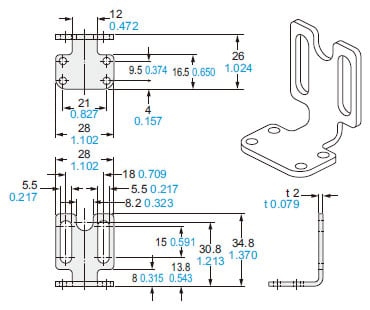
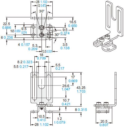
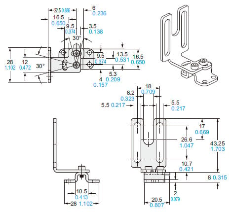
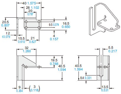
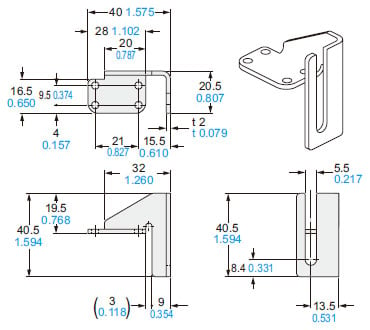
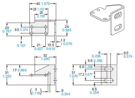
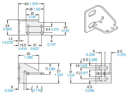
MS-SF2B-1
Standard mounting bracket (Optional)
MS-SF2B-1(R)
<Rear mounting>
<Side mounting>
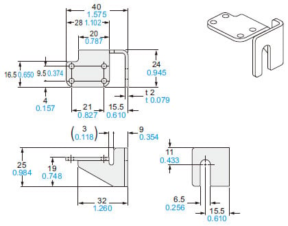
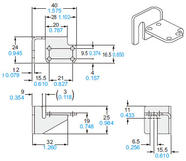
MS-SF2B-1(L)
<Rear mounting>
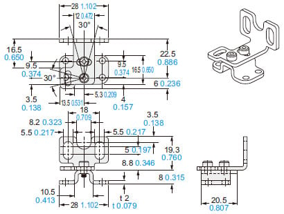
<Side mounting>
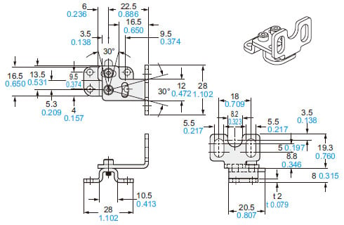
Material: Stainless steel (SUS304)
Four brackets (R type x 2 and L type x 2) per set.
[M3 (length 5 mm 0.197 in) hexagonsocket- head bolts (eight bolts for safety light curtain mounting, eight bolts for beam axis alignment) are attached.]
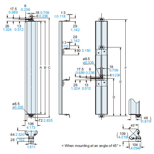
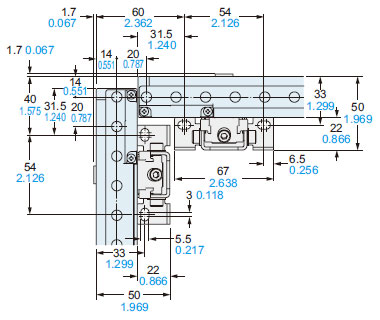
MS-SF2B-3
Dead zoneless mounting bracket (optional)
<Main body>
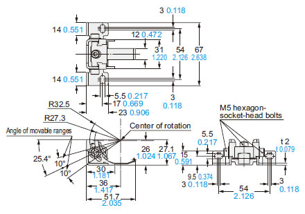
Material: Stainless steel (SUS304) ・ Die-cast zinc alloy
Four bracket set
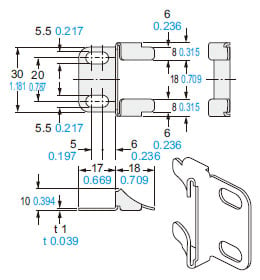
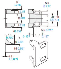
<Spacer for intermediate supporting bracket (Accessory)>
The spacer for intermediate supporting bracket MS-SF2B-2 can be used as a spacer for eliminating the dead zone when mounting the safety light curtain laterally.
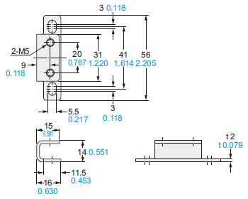
Material: Stainless steel (SUS304)
Six brackets set[Twelve M5 (length 8 mm 0.315 in) hexagon-socket-head bolts are attached.]
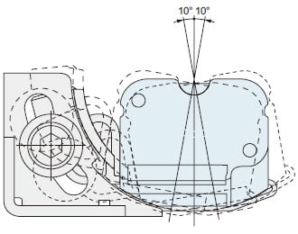
<L-shaped mounting>
<Mounting adjustment range>
The adjustment range of the safety light curtain angle is up to ±10 degrees.
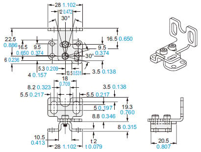
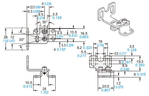
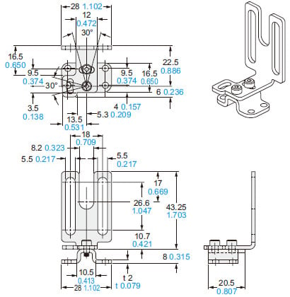
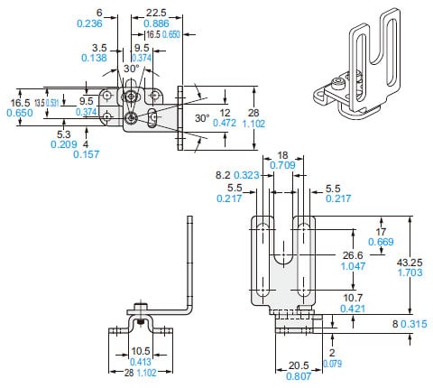
MS-SF2B-2
Intermediate supporting bracket (Accessory for safety light curtain)
<Rear mounting>
<Side mounting>
<For main unit mounting>
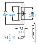
Material: Stainless steel (SUS304)
Two main unit mounting brackets per set (for rear mounting and side mounting) (Note)
Note:
The intermediate supporting bracket MS-SF2B-2 is enclosed with the following products. The quantity differs depending on the product as shown below:
[1 set]
SF2B-H□・・・ Safety light curtain with 40 to 56 beam channels
SF2B-A□ ・・・ Safety light curtain with 20 to 28 beam channels
[2 sets]
SF2B-H□ ・・・ Safety light curtain with 64 to 80 beam channels
SF2B-A□ ・・・ Safety light curtain with 32 to 40 beam channels
[3 sets]
SF2B-H□ ・・・ Safety light curtain with 88 to 96 beam channels
SF2B-A□ ・・・ Safety light curtain with 44 to 48 beam channels
MS-SF2B-4
Adapter mounting bracket for SF1-N / NA40 (Optional)
Material: Stainless steel (SUS304)Four bracket set[Eight M3 (length 5 mm 0.197 in) hexagon-socket-head bolts are attached.]
MS-SF2B-5
Adapter mounting bracket for SF2-A / SF2-N (Optional)
MS-SF2B-5(R)
<Rear mounting>
<Side mounting>
MS-SF2B-5(L)
<Rear mounting>
<Side mounting>
Material: Stainless steel (SUS304)
Four brackets (R type x 2 and L type x 2) per set
[M3 (length 5 mm 0.197 in) hexagonsocket-head bolts (eight bolts for safety light curtain mounting, eight bolts for beam axis alignment) are attached.]
MS-SF2B-6
Adapter mounting bracket for NA40 (Optional)
MS-SF2B-6(R)
MS-SF2B-6(L)
Material: Stainless steel (SUS304)Four brackets (R type x 2 and L type x 2) per set
[Eight M3 (length 5 mm 0.197 in) hexagon-socket-head bolts are attached.]
MS-SF2B-7
Adapter bracket for SF1-N (Optional)
<For upper-right surface mounting>
<For upper-left surface mounting>
<For lower-right surface mounting>
<For lower-left surface mounting>
Material: Stainless steel (SUS304)Four brackets (one of each type) per set
[Eight M3 (length 5 mm 0.197 in) hexagon-socket-head bolts are attached.]
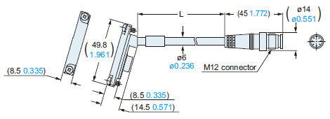
SF2B-CCB□
Bottom cap cable (Optional)
| Model No. | L |
|---|---|
| SF2B-CCB3 | 3,000 118.110 |
| SF2B-CCB7 | 7,000 275.590 |
| SF2B-CCB10 | 10,000 393.700 |
| SF2B-CCB15 | 15,000 590.551 |
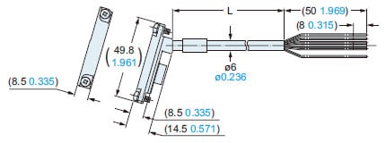
SF2B-CB□
Bottom cap cable (Optional)
| Model No. | L |
|---|---|
| SF2B-CB05 (-A/B) | 500 19.685 |
| SF2B-CB5 | 5,000 196.850 |
| SF2B-CB10 | 10,000 393.700 |
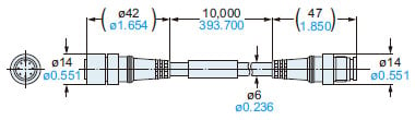
SFB-CC3 SFB-CC10
Extension cable (Optional)
| Model No. | L |
|---|---|
| SFB-CC3 | 3,000 118.110 |
| SFB-CC10 | 10,000 393.700 |
SFB-CCJ10E SFB-CCJ10D
Extension cable (Optional)
SF2B-CSL01 SF2B-CSL05
Cable for series connection (Optional)
| Model No. | L |
|---|---|
| SF2B-CSL01 | 100 3.937 |
| SF2B-CSL05 | 500 19.685 |
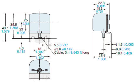
SF-LAT-2B
Laser alignment tool (Optional)
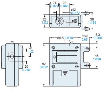
SF-IND-2
display unit for safety light curtain (Optional)
Material:
Bracket ・・・ Cold rolled carbon steel(SPCC)(Black chromate)
Enclosure ・・・ POM
Cover ・・・ Polycarbonate
I/O Circuit and Wiring diagrams
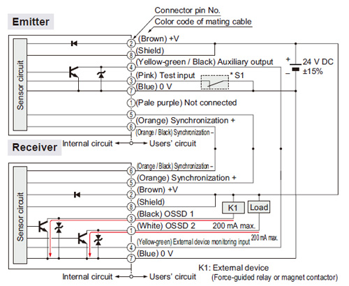
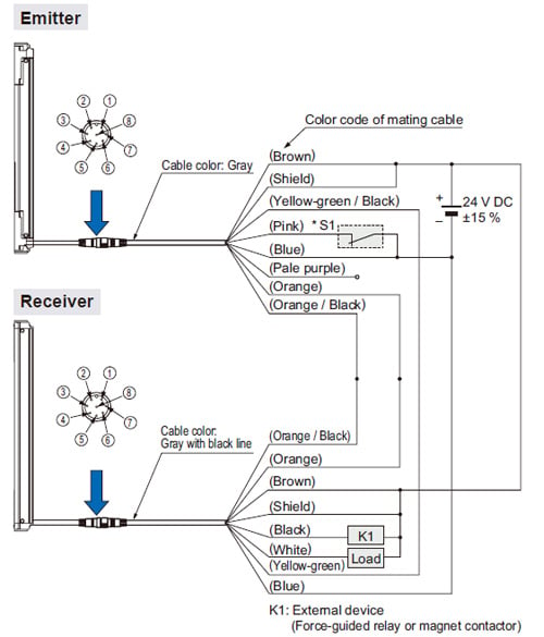
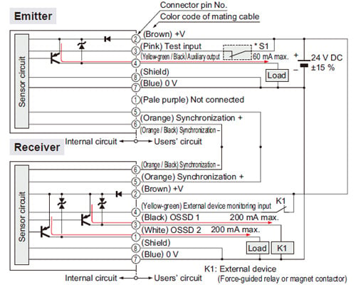
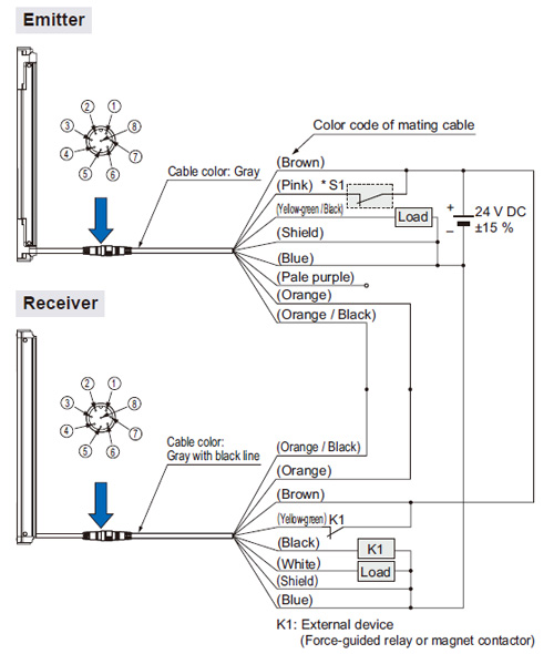
NPN output type
When using a SF2B-CCB□ or SF2B-CB□ bottom cap cable
I/O circuit diagram
<In case of setting the external device monitoring function to enabled>
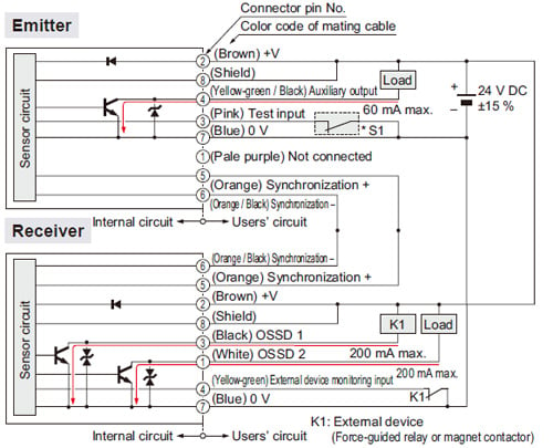
Note: Unused wires must be insulated to ensure that they do not come into contact with wires already in use.
CAUTION
Construct the interlock (reset input) circuit separately.
*S1
Switch S1
・Test input
Open: Emission halt
0 to +1.5 V (source current 5 mA or less): Emission
Wiring diagram
<In case of setting the external device monitoring function to enabled>
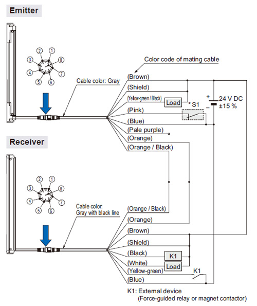
Note: Unused wires must be insulated to ensure that they do not come into contact with wires already in use.
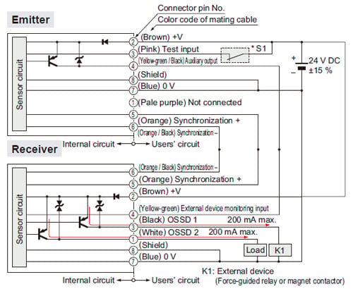
I/O circuit diagram
<In case of setting the external device monitoring function to disabled>
- In order to disable the external device monitoring function, connect the auxiliary output and external device monitoring input. At such times, do not connect a load to the auxiliary output.
Note: Unused wires must be insulated to ensure that they do not come into contact with wires already in use.
CAUTION
Construct the interlock (reset input) circuit separately.
*S1
Switch S1
・Test input
Open: Emission halt
0 to +1.5 V (source current 5 mA or less): Emission
Wiring diagram
<In case of setting the external device monitoring function to disabled>
Note: Unused wires must be insulated to ensure that they do not come into contact with wires already in use.
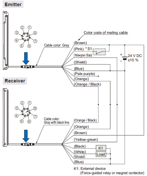
PNP output type
When using a SF2B-CCB□ or SF2B-CB□ bottom cap cable
I/O circuit diagram
<In case of setting the external device monitoring function to enabled>
Note: Unused wires must be insulated to ensure that they do not come into contact with wires already in use.
CAUTION
Construct the interlock (reset input) circuit separately.
*S1
Switch S1
・Test input
Open: Emission halt
Vs to Vs – 2.5 V (sink current 5 mA or less): Emission (Note 2)
Notes:
1) Unused wires must be insulated to ensure that they do not come into contact with wires already in use.
2) Vs is the applying supply voltage.
Wiring diagram
<In case of setting the external device monitoring function to enabled>
Note: Unused wires must be insulated to ensure that they do not come into contact with wires already in use.
I/O circuit diagram
<In case of setting the external device monitoring function to disabled>
- In order to disable the external device monitoring function, connect the auxiliary output and external device monitoring input. At such times, do not connect a load to the auxiliary output.
CAUTION
Construct the interlock (reset input) circuit separately.
*S1
Switch S1
・Test input
Open: Emission halt
Vs to Vs – 2.5 V (sink current 5 mA or less): Emission (Note 2)
Notes:
1) Unused wires must be insulated to ensure that they do not come into contact with wires already in use.
2) Vs is the applying supply voltage.
Wiring diagram
<In case of setting the external device monitoring function to disabled>
Note: Unused wires must be insulated to ensure that they do not come into contact with wires already in use.
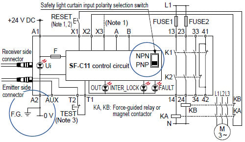
SF-C11
SF2B series wiring diagram (Control category 2)
For NPN output (plus ground)
- Set the safety light curtain input polarity selection switch to the NPN side and ground the + side.
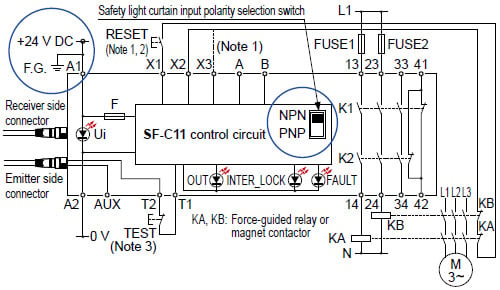
Notes:
1) The above diagram is when using manual reset. If automatic reset is used, disconnect the lead from X2 and connect it to X3. In this case, a reset (RESET) button is not needed.
2) Use a momentary-type switch as the reset (RESET) button.
3) Emission halt occurs when the test (TEST) button is open, and emission occurs when the test (TEST) button is short-circuited. If not using the test (TEST) button, short-circuit T1 and T2. However, use a test rod or similar to interrupt the light in order to carry out self-diagnosis separately.
For PNP output (minus ground)
- Set the safety light curtain input polarity selection switch to the PNP side and ground the 0 V line.
Notes:
1) The above diagram is when using manual reset. If automatic reset is used, disconnect the lead from X2 and connect it to X3. In this case, a reset (RESET) button is not needed.
2) Use a momentary-type switch as the reset (RESET) button.
3) Emission halt occurs when the test (TEST) button is open, and emission occurs when the test (TEST) button is short-circuited. If not using the test (TEST) button, short-circuit T1 and T2. However, use a test rod or similar to interrupt the light in order to carry out self-diagnosis separately.
Be sure to use the following mating cables when connecting SF-C11 to
SF2B series.
SF2B-CB05 (cable length: 0.5 m 1.640 ft)
SF2B-CB5 (cable length: 5 m 16.404 ft)
SF2B-CB10 (cable length: 10 m 32.808 ft)
SFB-CCJ10E (for emitter, cable length: 10 m 32.808 ft)
SFB-CCJ10D (for receiver, cable length: 10 m 32.808 ft)
Terminal arrangement diagram
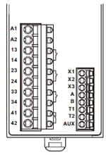
| Terminal | Function |
|---|---|
| A1 | +24 V DC |
| A2 | 0 V |
| 13-14, 23-24, 33-34 | Safety output (NO contact × 3) |
| 41-42 | Auxiliary output (NC contact × 1) |
| X1 | Reset output terminal |
| X2 | Reset input terminal (Manual) |
| X3 | Reset input terminal (Automatic) |
| A | Not used |
| B | |
| T1 | Test output terminal |
| T2 | Test input terminal |
| AUX | Semiconductor auxiliary output |
Pin layout for safety light curtain connectors
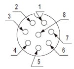
| Connector pin No. | Emitter side connector | Receiver side connector |
|---|---|---|
| 1 | Not used | OSSD2 |
| 2 | +24 V DC | +24 V DC |
| 3 | Emission halt | OSSD1 |
| 4 | Auxiliary output | EDM (External relay monitor) |
| 5 | Synchronization wire + | Synchronization wire + |
| 6 | Synchronization wire – | Synchronization wire – |
| 7 | 0 V | 0 V |
| 8 | Shield wire | Shield wire |
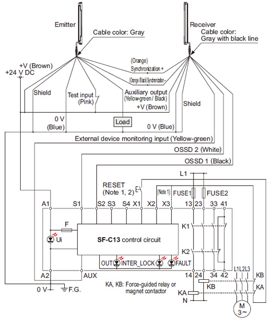
SF-C13
SF2B series wiring diagram (Control category 2)
NPN output type
- Connect the safety light curtain control outputs OSSD 1 and OSSD 2 to S4 and S2 respectively and ground the + side.
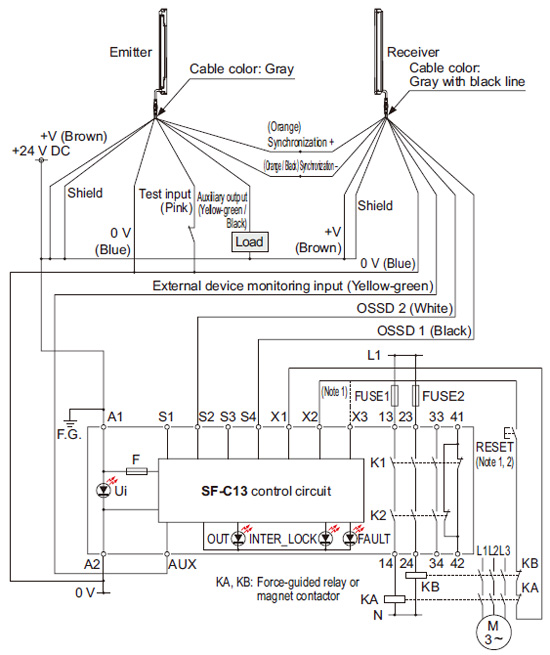
Notes:
1) The left diagram is when using manual reset. If automatic reset is used, disconnect the lead from X2 and connect it to X3. In this case, a reset (RESET) button is not needed.
2) Use a momentary-type switch as the reset (RESET) button.
PNP output type
- Connect the safety light curtain control outputs OSSD 1 and OSSD 2 to S1 and S2 respectively.
Notes:
1) The left diagram is when using manual reset. If automatic reset is used, disconnect the lead from X2 and connect it to X3. In this case, a reset (RESET) button is not needed.
2) Use a momentary-type switch as the reset (RESET) button.
Terminal arrangement diagram
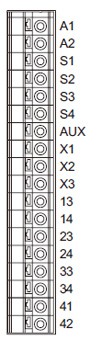
| Terminal | Function |
|---|---|
| A1 | +24 V DC |
| A2 | 0 V |
| S1 to S4 | Safety light curtain control output (OSSD) input terminal |
| AUX | Semiconductor auxiliary output |
| X1 | Reset output terminal |
| X2 | Reset input terminal (Manual) |
| X3 | Reset input terminal (Automatic) |
| 13-14, 23-24, 33-34 | Safety output (NO contact × 3) |
| 41-42 | Auxiliary output (NC contact × 1) |
Use a separate terminal block to carry out wiring for safety light curtains that cannot be connected to the SF-C13.
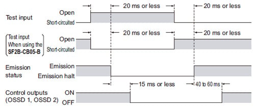
Emission halt function (Test input)
- This function stops the emission process of the emitter. You can select whether emission is on or halted by means of the connection status for the test input (pink).
| Test input | Emission status | |
|---|---|---|
| When using the SF2B-CB05-B | ||
| Open | Emission halt | Emission |
| Connected to 0 V or +V | Emission | Emission halt |
- During emission halt, the control outputs (OSSD 1, OSSD 2) become OFF status.
- By using this function, malfunction due to extraneous noise or abnormality in the control outputs (OSSD 1, OSSD 2) and the auxiliary output can be determined even from the machinery side.
<Time chart>
Auxiliary output
- Auxiliary output is incorporated into the emitter and its operation varies depending on the type of bottom cap cable (optional) to be used.
| Bottom cap cable | Normal mode | Lockout | ||
|---|---|---|---|---|
| Emission halt | Control outputs (OSSD 1, OSSD 2) status | |||
| Beam received | Beam interrupted | |||
| When using the SF2B-CCB□ / SF2B-CB□ | ON | OFF | ON | ON |
| When using the SF2B-CB05-A | OFF | ON | ON | OFF |
| SF2B-CB05-B | Cannot be used. | |||
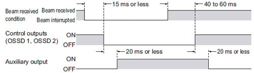
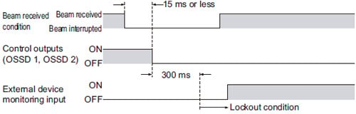
When bottom cap cable SF2B-CCB□ or SF2B-CB□ (optional) is used
- The auxiliary output is incorporated in the emitter. It is OFF when the control outputs (OSSD 1,OSSD 2) are ON and vice versa.
- The auxiliary output can be used as an operation monitor of the device.
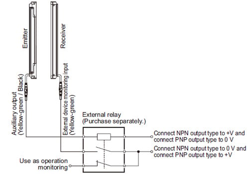
- When the external device monitor function is not used, connect the external device monitor input line to the auxiliary output line to disable the function.
In this case, do not connect the load to the auxiliary output. For details, refer to “External device monitoring function” and “I/O CIRCUIT AND WIRING DIAGRAMS”. - When the external device monitoring function is used to disable, do not directly use the auxiliary output as the operation monitor of this safety light curtain. When the external device monitor is used to disable and the auxiliary output is used to monitor the operation of safety light curtain, connect the auxiliary output and the external device monitoring input to the external relay (purchase separately) to use the external relay contacting point as an operation monitor of this safety light curtain.
<Time chart>
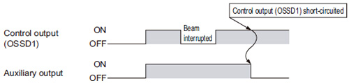
When bottom cap cable SF2B-CB05-A (optional) is used
- The auxiliary output is incorporated in the emitter. It outputs ON at the normal operation of device. It outputs OFF in the following cases:
・When an abnormality which needs emission halt status occurs [for example, the control output (OSSD 1) short-circuit and an error occurs.]
・While test input has been input - The error cannot be transmitted to the control machine. The alarm signal is output from the auxiliary output.
<Time chart>
When bottom cap cable SF2B-CB05-B (optional) is used
- The auxiliary output cannot be utilized by using the bottom cap cable SF2B-CB05-B (optional).
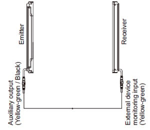
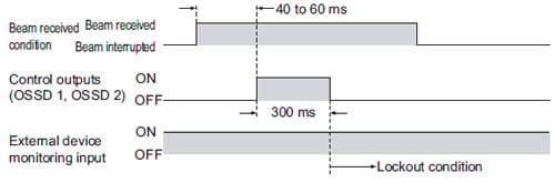
External device monitoring function
- This function is available when the bottom cap cable SF2B-CCB□ or SF2B-CB□ (optional) is used. This is the function for checking whether the external safety relay connected to the control outputs (OSSD 1, OSSD 2) performs normally in accordance with the control outputs (OSSD 1, OSSD 2) or not. Monitor the b contact of the external safety relay, and if any abnormality such as deposit of the contacting point, etc. is detected, change the status of the safety light curtain into lockout one, and turn OFF the control outputs (OSSD 1, OSSD 2).
In case of setting the external device monitoring function to enabled
- Connect the external device monitoring input (yellow-green) to the b contact of the external safety relay that is connected to the control outputs (OSSD 1, OSSD 2).
In case of not using the external device monitoring function
- Connect the external device monitoring input (yellow-green) to the auxiliary output (yellow-green / black).
<Time chart (normal)>
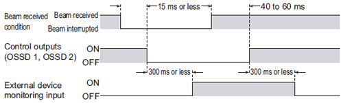
- The time set for external device monitoring is 300 ms or less. Exceeding 300 ms turns the safety light curtain into lockout condition.
<Time chart (Error 1 )>
<Time chart (Error 2 )>
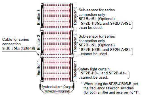
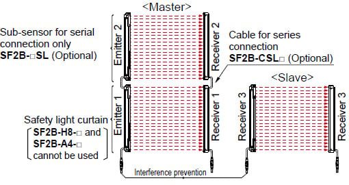
Series connection
Connectable up to 3 sets of safety light curtains (however, 128 beam channels max.) (Note 1, 2)
- This is the configuration for connecting multiple sets of emitters and receivers facing each other in series. It is used when the dangerous part can be entered from two or more directions. The control outputs (OSSD 1, OSSD 2) turns OFF if any of the safety light curtain is interrupted. For details, refer to the instruction manual.
Notes:
1): Series connection connectors cannot be used with the SF2B-H8-□ and SF2B-A4-□, and so series connection is not possible. The SF2B-H8SL and SF2B-A4SL are not equipped with series connection connectors, so when connecting three sets in series, they cannot be used in the middle position.
2): The total number of beam axes for the SF2B-A□ is a maximum of 96 when two sets are connected, and 64 when three sets are connected. When SF2B-H□ and SF2B-A□ are combined in series connection, double the number of the beam channels of SF2B-A□ to calculate the total number of beam channels, which should be 128 or less.
Example:
The total no. of beam channels for SF2B-H36 and SF2B-A44 is 124. The no. of beam channels of SF2B-H36 + (the No. of beam channels of SF2B-A44 × 2) = Total no. of beam channels 36 beam channels + (44 beam channels × 2) = 124 beam channels
Parallel connection
- Up to a maximum of two sets can be connected in parallel only when using the SF2B-CB05-B adapter cable (optional). For details, refer to the instruction manual.
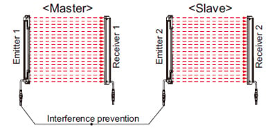
*Set the frequency selection switches (for both emitter and receiver) to “1” at the master units, and set them to “2” at the slave units.
Series and parallel mixed connection
- Up to a maximum of three sets can be connected in a mixture of series and parallel (for a total maximum number of 128 beam channels. However, the total number of beam channels for the SF2B-A□ is a maximum of 96 when two sets are connected, and 64 when three sets are connected.) only when using the SF2B-CB05-B adapter cable (optional). For details, refer to the instruction manual.
*Set the frequency selection switches (for both emitter and receiver) to “1” at the master units, and set them to “2” at the slave units.
Part description and function
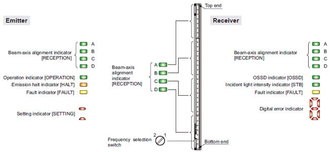
| Description | Function | |
|---|---|---|
| Beam-axis alignment indicator (Red / Green) [RECEPTION] | A | When all beam channels of safety light curtain top are receiving light: lights up in red When safety light curtain top end receives light: blinks in red When control outputs (OSSD 1, OSSD 2) are ON: lights up in green (always off when using the SF2B-CB05-B) |
| B | When all beam channels of safety light curtain upper middle are receiving light: lights up in red When control outputs (OSSD 1, OSSD 2) are ON: lights up in green (always off when using the SF2B-CB05-B) | |
| C | When all beam channels of safety light curtain lower middle are receiving light: lights up in red When control outputs (OSSD 1, OSSD 2) are ON: lights up in green(always off when using the SF2B-CB05-B) | |
| D | When all beam channels of safety light curtain bottom are receiving light: lights up in red When sensor bottom end receives light: blinks in red When control outputs (OSSD 1, OSSD 2) are ON: lights up in(always off when using the SF2B-CB05-B) | |
| Operation indicator (Red / Green) [OPERATION] | When control outputs (OSSD 1, OSSD 2) are OFF: lights up in red When control outputs (OSSD 1, OSSD 2) are ON: lights up in green (When using the SF2B-CB05-B When fault occurs in the emitter: light up in red When emitter is normal: light up in green) | |
| Emission halt indicator (Orange) [HALT] | When light emission is halt: lights up When light is emitted: lights off | |
| Fault indicator (Yellow) [FAULT] | When fault occurs in the sensor: lights up or blinks | |
| Setting indicator (Red) [SETTING] | Always off (When using the SF2B-CB05-B One lights up when set to Frequency 1 Two light up when set to Frequency 2) | |
| Frequency selection switch | Used for switching between master and slave when using the SF2B-CB05-B. Set to “1” for master and “2” for slave. | |
| Description | Function | |
|---|---|---|
| Beam-axis alignment indicator (Red / Green) [RECEPTION] | A | When all beam channels of safety light curtain top are receiving light: lights up in red When sensor top end receives light: blinks in red When control outputs (OSSD 1, OSSD 2) are ON: lights up in green |
| B | When all beam channels of safety light curtain upper middle are receiving light: lights up in red When control outputs (OSSD 1, OSSD 2) are ON: lights up in green | |
| C | When all beam channels of safety light curtain upper middle are receiving light: lights up in red When control outputs (OSSD 1, OSSD 2) are ON: lights up in green | |
| D | When all beam channels of safety light curtain bottom are receiving light: lights up in red When sensor bottom end receives light: blinks in red When control outputs (OSSD 1, OSSD 2) are ON: lights up in green | |
| OSSD indicator (Red / Green) [OSSD] | When control outputs (OSSD 1, OSSD 2) are OFF: lights up in red When control outputs (OSSD 1, OSSD 2) are ON: lights up in green | |
| Incident light intensity indicator (Orange / Green) [STB] | When sufficient light is received (incident light intensity: 130 % or more) (Note 1): lights up in green When stable light is received (incident light intensity: 115 to 130 %) (Note 1): OFF When unstable light is received (incident light intensity: 100 to 115 %) (Note 1): lights up in orange When light is interrupted: OFF (Note 2) | |
| Fault indicator (Yellow) [FAULT] | When fault occurs in the sensor: lights up or blinks | |
| Digital error indicator (Red)(Note 3) | When device is lockout: lights up for malfunction content (When using the SF2B-CB05-B Display shows fault contents during lockout. Center lights up when set to Frequency 1 Center and bottom lights up when set to Frequency 2) | |
| Frequency selection switch | Used for switching between master and slave when using the SF2B-CB05-B. Set to “1” for master and “2” for slave. | |
Notes:
1) The threshold value where the control output changes from OFF to ON is applied as “100 % incident light intensity”.
2) The status “when light is interrupted” refers to the status that the some obstacle is existed in the sensing area.
3) For details, refer to “Troubleshooting” and the SF2B instruction manual.
4) The description given in [ ] is marked on the safety light curtain.
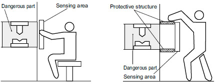
Wiring
Example of correct sensing area setup
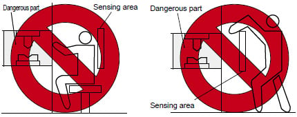
Example of incorrect sensing area setup
Safety distance
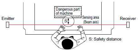
- Safety distance is calculated based on the following equation when a person moves perpendicular (normal intrusion) to the sensing area of the safety light curtain. In case the intrusion direction is not perpendicular to the sensing area, be sure to refer to the relevant standard (regional standard, specification of the machine, etc.) for details of the calculation. (Please check the latest standards for the equation.)
For use based on EN ISO 13855 / ISO 13855 / JIS B 9715
For intrusion direction perpendicular to the sensing area
Equation 1 S = K × T + C
S: Safety distance (mm)
Minimum required distance between the sensing area surface and the dangerous parts of the machine
K: Intrusion speed of operator’s body or objects (mm/sec.)
Normally, taken as SF2B-H□ 2,000 (mm/sec.),
SF2B-A□ 1,600 (mm/sec.) for calculation.
T: Response time of total equipment (sec.)
T = Tm + TSF2B
Tm: Maximum halting time of machinery (sec.)
TSF2B: Response time of the SF2B series 0.015 (sec.)
C: Additional distance calculated from the size of the minimum sensing object of the safety light curtain (mm)
However, the value of “C” cannot be 0 or less.
C = 8 × (d – 14)
d: Minimum sensing object diameter
SF2B-H□: d= 27 (mm) 1.063 (in), C = 104 (mm) 4.094 (in)
For SF2B-A□, C = 850 (mm) 33.465 (in) (constant)
・For calculating the safety distance “S”, there are the following five cases. First calculate by substituting the value K = 2,000 (mm/sec.) in the equation above.
Then, classify the obtained value of “S” into three cases, 1) S < 100, 2) 100 ≤ S ≤ 500, and 3) S > 500. For Case 3) S > 500, recalculate by substituting the value K = 1,600 (mm/sec.). After that, classify the calculation result into two cases, 4) S ≤ 500 and 5) S > 500. For details, refer to the instruction manual enclosed with this product.
For use based on ANSI B11.19
Equation 2 S = K × (Ts + Tc + TSF2B + Tbm) + Dpf
S: Safety distance (mm)
Minimum required distance between the sensing area surface and the dangerous parts of the machine
K: Intrusion velocity {Recommended value in OSHA is 63 (inch/sec.)
≈ 1,600 (mm/sec.)}
ANSI B11.19 does not define the intrusion velocity “K”. When determining K,
consider possible factors including physical ability of operators.
Ts: Halting time calculated from the operation time of the control element (air valve, etc.) (sec.)
Tc: Maximum response time of the control circuit required for functioning the brake (sec.)
TSF2B: Response time of safety light curtain 0.015 (sec.)
Tbm: Additional halting time tolerance for the brake monitor (sec.)
Tbm = Ta – (Ts + Tc)
Ta: Setting time of brake monitor (sec.)
When the machine is not equipped with a brake monitor, it is recommended
that 20 % or more of
(Ts + Tc) is taken as additional halting time.
Dpf: Additional distance calculated from the size of the minimum sensing object of the safety light curtain
SF2B-H□ Dpf = 2.676 (inch) ≈ 68 (mm)
SF2B-A□ Dpf = 5.355 (inch) ≈ 136 (mm)
Dpf = 3.4 × (d – 0.276) (inch)
Dpf ≈ 3.4 × (d – 7) (mm)
d: Minimum sensing object diameter 1.063 (inch) ≈ 27 (mm) SF2B-H□
Minimum sensing object diameter 1.851 (inch) ≈ 47 (mm) SF2B-A□
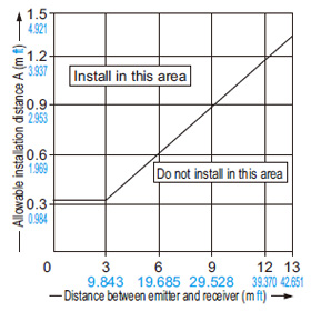
Influence of reflective surfaces
- Keep the minimum distance given below, between the safety light curtain and a reflective surface.
Side view
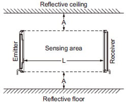
| Distance between emitter and receiver (Setting distance L) | Allowable installation distance A |
|---|---|
| 0.2m ≦ L ≦ 3m 0.656 ≦ L ≦ 9.843 ft | 0.32 m 1.050 ft |
| 3m < L ≦ 13m 9.843 < L ≦ 42.651 ft (Note 1) | L / 2 × tan2θ = L × 0.106 (m) 0.348 (ft) (θ = 6°) |
Top view
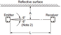
Notes:
1) If using the SF2B-CB05-B, the operating range is 0.3 to 5 m 0.984 to 16.404 ft.
2) The effective aperture angle for this device is ±5°or less (when L > 3 m 9.843 ft) as required by IEC 61496-2 / UL 61496-2.
However, install this device away from reflective surfaces considering an effective aperture angle of ±6° to take care of beam misalignment, etc. during installation.
Troubleshooting
Emitter side
| Phenomenon | Cause | Remedy |
|---|---|---|
| All indicators are off. | Power is not being supplied. | Check that the power supply capacity is sufficient. Connect the power supply correctly. |
| Supply voltage is out of the specified range. | Provide the supply voltage within the specified range. | |
| Connector is not connected securely. | Connect the connector securely. | |
| Operation indicator remains lit up in red (beam is not received). [OPERATION]  | The beam channels of the emitter and the receiver are not correctly aligned. | Align the beam channels. |
| Emission halt indicator (orange) lights up. [HALT]  | Emission is in halt condition. | Connect the test input (emission halt input) wire correctly. The logic varies depending on the cable to be used. |
| The synchronization wire error | Connect the synchronization wire correctly. | |
| The receiver does not work. | Check the operation of the receiver side. | |
| The interference prevention wire error (When using the SF2B-CB05-B: When set to slave) | Connect the interference prevention wire correctly. | |
| Master / slave setting error (When using the SF2B-CB05-B: When set to master) | Set the master / slave setting to “master”. | |
| The master sensor does not work. | Check the master side safety light curtain. | |
| Fault indicator (yellow) lights up or blinks. [FAULT]  | [Blinks once] Total safety light curtains No. / total beam channel No. error | Connect the end cap properly. Connect the cable for series connection correctly. Check the model (emitter / receiver) of sub-sensor for series connection. Set the No. of the safety light curtains in series connection, and a total No. of beam channels within the specification. |
| [Blinks twice] Auxiliary output error | Connect the auxiliary output cable correctly. | |
| [Other than the above] Effect from noise / power supply or failure of internal circuit | Check the noise status around this safety light curtains. Check the wiring, supplied voltage and power supply capacity. Even if the error is not eliminated, contact our office. |
Receiver side
| Phenomenon | Cause | Remedy |
|---|---|---|
| All indicators are off. | Power is not being supplied. | Check that the power supply capacity is sufficient. Connect the power supply correctly. |
| Supply voltage is output of the specified range. | Set the supply voltage correctly. | |
| Connector is not connected securely. | Connect the connector securely. | |
| OSSD indicator remains lit up in red (beam is not received). [OSSD] | The beam channels of the emitter and the receiver are not correctly aligned. | Align the beam channels. |
| Total unit No. / total beam channel No. error | Set the same value to the Nos. of emitter and receiver. | |
| The master / slave setting is different. (When using with the SF2B-CB05-B) | Set the setting identically. | |
| Stable indicator lights up (Orange) [STB] | The beam channels of the emitter and the receiver are not correctly aligned. | Align the beam channels. |
| Fault indicator (yellow) lights up or blinks. [FAULT] | [Digital error indicator 1 ] Total safety light curtain No. / total beam channel No. error | Connect the end cap properly. Connect the cable for series connection correctly. Check the model (emitter / receiver) of sub sensor for series connection. Check that the number of safety light curtains / number of beam axes is within the specification value. |
| [Digital error indicator 2 ] Control outputs (OSSD 1, OSSD 2) error | Connect the control outputs (OSSD1, OSSD2) correctly. | |
| [Digital error indicator 4 ] Extraneous light error | Prevent any extraneous light from entering the receiver. | |
| [Digital error indicator 7 ] External device monitoring error | Connect the external device monitor input wire correctly. Replace the replay unit. Replace the relay unit having appropriate response time. | |
| [Digital error indicator 6 ] Bottom connector error | Check the type of the bottom connector. Cable of the emitter: Gray (with black stripe) | |
| [Other than the above] Effect from noise / power supply or failure of internal circuit | Check the noise status around this safety light curtain. Check the wiring, supplied voltage and power supply capacity. Even if the error is not eliminated, contact our office. |