Applicable
standards | International standards | IEC 61496-1/3 (Type 3), ISO 13849-1 (Category 3, PLd), IEC 61508-1 to 7 (SIL2), IEC 62061 (SIL2) |
|---|
| Japan | JIS B 9704-1/3 (Type 3), JIS B 9705-1 (Category 3), JIS C 0508 (SIL2) |
|---|
| Europe (EU) | EN 61496-1 (Type 3), ISO 13849-1 (Category 3, PLd), EN 61508-1 to 7 (SIL2) |
|---|
Detection
zone | Min. sensing object setting | ø150 mm
ø5.906 in | ø70 mm
ø2.756 in | ø50 mm
ø1.969 in | ø40 mm
ø1.575 in | ø30mm
ø1.181 in |
|---|
| Sensing range (radius) | 0 to 4.0 m
0 to 13.123 ft | 0 to 4.0 m
0 to 13.123 ft | 0 to 2.8 m
0 to 9.186 ft | 0 to 2.2 m
0 to 7.218 ft | 0 to 1.6m
0 to 5.249 ft |
|---|
| | Measurement error
margin extended range | When dust suppression function is not selected: 83mm 3.268 in
When dust suppression function is selected: 83 mm 3.268 in for less than 3.5 mm 0.138 in, and 100 mm 3.937 in for 3.5 mm 0.138 in or more
(automatically calculated using the included software) |
|---|
| Sensing object reflectance | Minimum 1.8 % |
|---|
Warning
zone | Min. sensing object setting | ø150 mm ø5.906 in (fixed) |
|---|
| Sensing range (radius) | 0 to 15 m 0 to 49.213 ft |
|---|
| Sensing object reflectance | Minimum 20 % |
|---|
| Measurement zone | Max. measurement range (radius) | 50 m 164.042 ft (fixed) |
|---|
| Scanning angle | 190° / 180° (by setting) |
|---|
| Number of zone setting | Max. 7 + 1 (without detection zone)
[Zone pairs in combination of detection zone and warning zone can be switched over by external input] |
|---|
| Min. zone setting range | 200 mm 7.874 in |
|---|
| Supply voltage (UB) | 24 V DC+20-30 % (IEC 60742) |
|---|
| Current consumption | 300 mA approx. (excluding external connection load) |
|---|
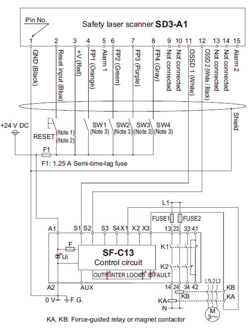
| Fuse (power supply) | 1.25 A semi-time-lag fuse |
|---|
Control outputs
(OSSD 1, OSSD 2) | PNP open-collector transistor 2 outputs
• Rated operating voltage: supply voltage (UB) - 3.2 V
• Max. source current: 250 mA
• Residual voltage: 3.2 V or less |
|---|
| | Operation mode | When no object enters into the detection zone: ON, When an object enters: OFF |
|---|
| Response time | Min. 80 ms (2 scans) to max. 640 ms (16 scans) switching method |
|---|
| Protection circuit | Incorporated |
|---|
Warning output 1
(Alarm 1) | PNP open-collector transistor
• Rated operating voltage: supply voltage (UB) - 4 V
• Max. source current: 100 mA
• Residual voltage: 4 V or less |
|---|
| | Operation mode | Switching method of operation mode (set by below)
• Not used
• Main unit at normal operation: ON, Abnormal operation: OFF
• When no object enters into the warning zone: ON, When an object enters: OFF
• Main unit at normal operation: ON, Abnormal operation: OFF and When no object enters into the warning zone: ON, When an object enters: OFF |
|---|
| Response time | Min. 80 ms (2 scans) to max. 640 ms (16 scans) switching method |
|---|
Warning output 2
(Alarm 2) | PNP open-collector transistor
• Rated operating voltage: supply voltage (UB) - 4 V
• Max. source current: 100 mA
• Residual voltage: 4 V or less |
|---|
| | Operation mode | Main unit at normal operation: ON, Abnormal operation: OFF |
|---|
| Laser protection class | Class 1 [IEC 60825] |
|---|
| Peak emission wavelength | 905 nm 0.036 mil |
|---|
| Degree of protection | IP65 |
|---|
| Ambient temperature | 0 to +50 ℃ +32 to +122 ℉
Storage: −20 to +60 ℃ −4 to +140 ℉ |
|---|
| Ambient humidity | Operation and storage: Max. 95 % RH (No dew condensation) |
|---|
Vibration resistance /
Shock resistance | 10 to 150 Hz frequency, 5 G max. (50 m/s2 approx.) in X, Y and Z directions for twenty times each |
|---|
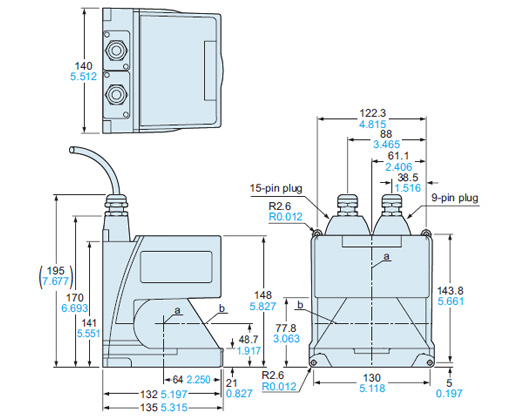
| Maximum cable length | 15-pin plug: Max. 50 m 164.042 ft,
9-pin plug: Max. 10 m 32.808 ft (when using RS-232C) / Max. 50 m 164.042 ft (when using RS-422)
(by using optional connection cable) (Note 1) |
|---|
| Material | Main body: Die-cast aluminum, Scanner window: Thermoplastic resin |
|---|
| Accessories | SD3-PS (exclusive 15-pin connector): 1 pc.,
SD3-RS232 (exclusive 9-pin connector): 1 pc.,
Mounting screws [M5 (length 20 mm 0.787 in) hexagon-socket-head bolt: 2 pcs., M5 (length 16 mm 0.630 in) hexagon-socket-head bolt: 2 pcs., attached to SD3-PS]:1 set,
Simplified instruction manual: 1 copy,
Installation CD-ROM (includes detailed instruction manual data): 1 CD |
|---|
| Weight | Net weight: 2.1 kg approx., Gross weight: 2.9 kg approx. |
|---|