------------------------------ Tab1 showing ------------------------------
Basic Information
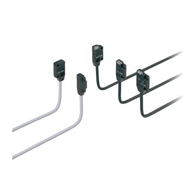
Amplifier built-in extraordinarily small and slim size


CE : Excluding EX-15□/17□
UKCA : Excluding EX-15□/17□
UL : Recognition(Excluding some models)
*Please check ."Order guide" for the compliant model no.
*Be sure to read the "Cautions For Use" when using for the above applications.
*Before using this device, be sure to confirm the standards / regulations applied in the relevant nation and region.
*If you need the Certificate or Confirmation Letter, please contact us.![]()
Features
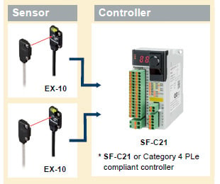
Sensor unit complies with ISO 13849-1*1 Category 1 PLc*2
A Category 3 PLd Safety System can be built by using Category 4 PLe compliant controllers together with our sensors
*1 Safety-related parts of control systems, Part 1: General principles for design
*2 Conformed from December 2021 production.
■ Category 3, PLd construction example
[Precautions when using as Category 3 PLd]
Sensor redundancy is required!
Observe the following when connecting to the safety controller.
・In the case the product is used in a standalone state, the safety system may not operate properly when a sensor malfunction occurs.
CAUTION
The product cannot be used for human body detection.
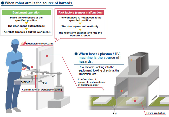
■ Application examples
[Required conditions]
1.The source of hazards is located inside the machine and may cause hazards to nearby people.
2.The equipment is classified as Category 3 PLd or lower.
3.The source of hazards is isolated only by the automatic door.
* The product can be used safely when all of the above conditions 1 through 3 are satisfied!
* There are cases where you can use it under other conditions.
*Be sure to read the "Cautions For Use" when using for safety applications.
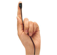
Smallest body, just 3.5 mm 0.138 in thick
It can be mounted in a very small space as its size is just
W10 x H14.5 x D3.5 mm
W0.394 x H0.571 x D0.138 in (thru-beam, front sensing type).
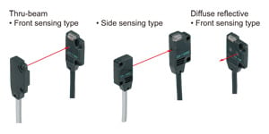
Flexible mounting
The diffuse reflective type sensor is front sensing and is so thin that it gives an impression of being just pasted on the mounting base. The thru-beam type is available as front sensing type, as well as, side sensing type, allowing flexible mounting.
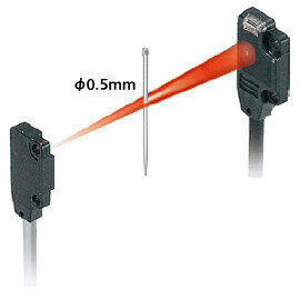
A wide variety of narrow-beam type! Light diffusion is approx. 1/2 of standard type. [EX-□S□]
Less interference with no slit, narrow-pitch can be set.
The pitch of installation is 1/2 of conventional models, so that the close-installation is possible. No cost is necessary to purchase or install a slit.
Possible to sense a minute object less than ø0.5 mm ø0.039 in with no slit.
The series is applicable to sense a minute object without any cost.
Long sensing range of 1 m 3.281 ft with narrow beam
A long 1 m 3.281 ft sensing range is possible with narrow beam.
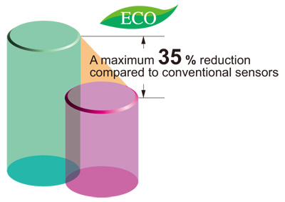
Electric power saving
The EX-10 series achieves reductions in power consumption of up to 65 %. These sensors contribute to environmental friendliness.
High-speed response time: 0.5 ms
The sensor is suitable for detecting small and high-speed traveling objects.
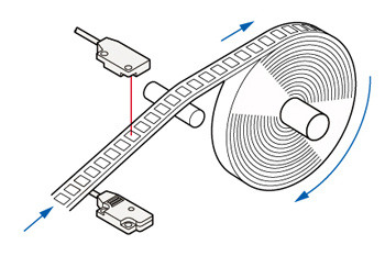
Minimum sensing object: ø1 mm ø0.039 in [EX-11(E)□, EX-15(E)□]
EX-11□, EX-11E□, EX-15 and EX-15E are incorporated with ø1 mm ø0.039 in slit masks so that ø1 mm ø0.039 in, or more, object can be detected. Hence, they are suitable for precise positioning or small parts detection.
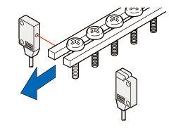
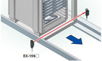
Long sensing range: 1 m 3.281 ft [EX-19(E)□]
A sensing range of 1 m 3.281 ft has been realized with a slim size of just 3.5 mm 0.138 in. It can be used to detect even wide IC trays.

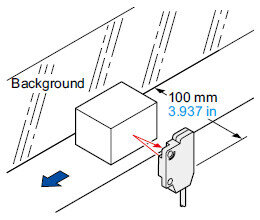
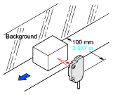
Background suppression [EX-14□]
Hardly affected by background
Even a specular background separated by 100 mm 3.937 in, or more, is not detected. (However, the background should be directly opposite. A spherical or curved background may be detected.)
Black object reliably detected
It can reliably detect dark color objects since it is convergent reflective type.
Incorporated an inverter countermeasure circuit
The EX-10 series become significantly stronger against inverter light and other extraneous light.
Waterproof IP67
The sensors features an IP67 rating to allow their use in process lines where water is used or splashed.
Rust-resistant stainless steel sensor mounting brackets are available.
Note: If water splashes on the sensor during sensing operation, it may sense water as an object.
Bending durability [EX-□-R]
Bending-resistant cable type EX-□-R is available. It is most suitable for moving parts, such as robot arm, etc.
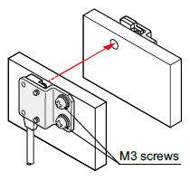
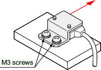
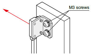
Mountable with M3 screws
Non-corrosive stainless steel type sensor mounting bracket is also available.
Note: Sensor mounting brackets can not be used for the narrow beam type (EX-□S□).
MS-EX10-1 [Cold rolled carbon steel (SPCC)]
MS-EX10-11 [Stainless steel (SUS304)]
(mounting bracket for the front sensing type)
MS-EX10-2 [Cold rolled carbon steel (SPCC)]
MS-EX10-12 [Stainless steel (SUS304)]
(mounting bracket for the side sensing type)
MS-EX10-3 [Cold rolled carbon steel (SPCC)]
MS-EX10-13 [Stainless steel (SUS304)]
(L-shaped mounting bracket)
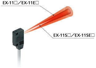
Red beam makes beam alignment easy
The red LED beam projected from the emitter helps you to align the sensor heads.
Less resources used
Based on environmental considerations, simplified packaging is used in order to reduce waste.
In addition, the bag is made from polyethylene which produces no toxic gases even when burned.

------------------------------ Tab2 showing ------------------------------


------------------------------ Tab3 showing ------------------------------
Order guide
| Type | Appearance | Sensing range | Model No. (Note 2) | Output operation | Output | ||||
|---|---|---|---|---|---|---|---|---|---|
| NPN output | PNP output | ||||||||
| Standard type | Thru-beam | Front sensing |
| 150 mm 5.906 in | EX-11A | EX-11A-PN | Light-ON | NPN opencollector transistor or PNP opencollector transistor | |
| EX-11B | EX-11B-PN | Dark-ON | |||||||
| 500mm 19.685 in | EX-13A | EX-13A-PN | Light-ON | ||||||
| EX-13B | EX-13B-PN | Dark-ON | |||||||
| 1m 3.281 ft | EX-19A | EX-19A-PN | Light-ON | ||||||
| EX-19B | EX-19B-PN | Dark-ON | |||||||
| With operation mode switch on the bifurcation | 150 mm 5.906 in | EX-15 | - | Switchable either Light-ON or Dark-ON | |||||
| 500mm 19.685 in | EX-17 | - | |||||||
| Side sensing |
| 150 mm 5.906 in | EX-11EA | EX-11EA-PN | Light-ON | ||||
| EX-11EB | EX-11EB-PN | Dark-ON | |||||||
| 500mm 19.685 in | EX-13EA | EX-13EA-PN | Light-ON | ||||||
| EX-13EB | EX-13EB-PN | Dark-ON | |||||||
| 1m 3.281 ft | EX-19EA | EX-19EA-PN | Light-ON | ||||||
| EX-19EB | EX-19EB-PN | Dark-ON | |||||||
| With operation mode switch on the bifurcation | 150 mm 5.906 in | EX-15E | - | Switchable either Light-ON or Dark-ON | |||||
| 500mm 19.685 in | EX-17E | - | |||||||
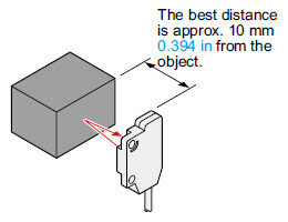
| Convergent reflective (Diffused beam type) | Front sensing |
| 2 to 25 mm 0.079 to 0.984 in (Note 1) (Convergent point: 10 mm 0.394 in) | EX-14A | EX-14A-PN | Light-ON | |||
| EX-14B | EX-14B-PN | Dark-ON | |||||||
| PNPNarrow beam type | Thru-beam | Front sensing |
| 150 mm 5.906 in | EX-11SA | EX-11SA-PN | Light-ON | NPN opencollector transistor or PNP opencollector transistor | |
| EX-11SB | EX-11SB-PN | Dark-ON | |||||||
| 500mm 19.685 in | EX-13SA | EX-13SA-PN | Light-ON | ||||||
| EX-13SB | EX-13SB-PN | Dark-ON | |||||||
| 1m 3.281 ft | EX-19SA | EX-19SA-PN | Light-ON | ||||||
| EX-19SB | EX-19SB-PN | Dark-ON | |||||||
| Side sensing |
| 150 mm 5.906 in | EX-11SEA | EX-11SEA-PN | Light-ON | ||||
| EX-11SEB | EX-11SEB-PN | Dark-ON | |||||||
| 500mm 19.685 in | EX-13SEA | EX-13SEA-PN | Light-ON | ||||||
| EX-13SEB | EX-13SEB-PN | Dark-ON | |||||||


NOTE : Mounting bracket is not supplied with the sensor. Please select from the range of optional sensor mounting brackets (MS-EX10-□). Sensor mounting brackets (MS-EX10-□) can not be used for the narrow beam type (EX-□S□).
Note 1 : The sensor does not detect even a specular background if it is separated by 100 mm 3.937 in or more. (However, the background should be directly opposite. A spherical or curved background may be detected.)
Note 2 : The model No. with "P" shown on the label affixed to the thru-beam type sensor is the emitter, "D" shown on the label is the receiver.
Bending-resistant cable type
Bending-resistant cable type is also available for NPN output type. (excluding narrow beam type EX-□S□ and sensor with operation mode switch on the bifurcation EX-15□/17□)
When ordering this type, suffix "-R" to the model No.
(e.g.) Bending-resistant cable type of EX-11A is "EX-11A-R".
| Standard type | Bending-resistant cable type |
|---|---|
| EX-11A | EX-11A-R |
| EX-11B | EX-11B-R |
| EX-13A | EX-13A-R |
| EX-13B | EX-13B-R |
| EX-19A | EX-19A-R |
| EX-19B | EX-19B-R |
| EX-11EA | EX-11EA-R |
| EX-11EB | EX-11EB-R |
| EX-13EA | EX-13EA-R |
| EX-13EB | EX-13EB-R |
| EX-19EA | EX-19EA-R |
| EX-19EB | EX-19EB-R |
| EX-14A | EX-14A-R |
| EX-14B | EX-14B-R |
5 m 16.404 ft cable length type
5 m 16.404 ft cable length type (standard: 2 m 6.562 ft) is also available for NPN output type. (excluding narrow beam type EX-□S□ and bending-resistant cable type)
When ordering this type, suffix "-C5" to the model No.
(e.g.) 5 m 16.404 ft cable length type of EX-11A is "EX-11A-C5".
| Standard type | 5 m 16.404 ft cable length type |
|---|---|
| EX-11A | EX-11A-C5 |
| EX-11B | EX-11B-C5 |
| EX-13A | EX-13A-C5 |
| EX-13B | EX-13B-C5 |
| EX-19A | EX-19A-C5 |
| EX-19B | EX-19B-C5 |
| EX-15 | EX-15-C5 |
| EX-17 | EX-17-C5 |
| EX-11EA | EX-11EA-C5 |
| EX-11EB | EX-11EB-C5 |
| EX-13EA | EX-13EA-C5 |
| EX-13EB | EX-13EB-C5 |
| EX-19EA | EX-19EA-C5 |
| EX-19EB | EX-19EB-C5 |
| EX-15E | EX-15E-C5 |
| EX-17E | EX-17E-C5 |
| EX-14A | EX-14A-C5 |
| EX-14B | EX-14B-C5 |
ISO 13849 -1 Category 1, PLc compliant model no. list
| Type | NPN output | PNP output | ||
|---|---|---|---|---|
| Standard | 5 m 16.404 ft cable length | Bending-resistant cable | Standard | |
| Thru-beam | EX-11A | EX-11A-C5 | EX-11A-R | EX-11A-PN |
| EX-11B | EX-11B-C5 | EX-11B-R | EX-11B-PN | |
| EX-11EA | EX-11EA-C5 | EX-11EA-R | EX-11EA-PN | |
| EX-11EB | EX-11EB-C5 | EX-11EB-R | EX-11EB-PN | |
| EX-13A | EX-13A-C5 | EX-13A-R | EX-13A-PN | |
| EX-13B | EX-13B-C5 | EX-13B-R | EX-13B-PN | |
| EX-13EA | EX-13EA-C5 | EX-13EA-R | EX-13EA-PN | |
| EX-13EB | EX-13EB-C5 | EX-13EB-R | EX-13EB-PN | |
| EX-19A | EX-19A-C5 | EX-19A-R | EX-19A-PN | |
| EX-19B | EX-19B-C5 | EX-19B-R | EX-19B-PN | |
| EX-19EA | EX-19EA-C5 | EX-19EA-R | EX-19EA-PN | |
| EX-19EB | EX-19EB-C5 | EX-19EB-R | EX-19EB-PN | |
| Convergent reflective | EX-14A | EX-14A-C5 | EX-14A-R | EX-14A-PN |
| EX-14B | EX-14B-C5 | EX-14B-R | EX-14B-PN | |
Notes :
1) :Conformed from December 2021 production. When ordering a product that complies with safety standards, please order Lot No. "1L1" (First 3 digits) or later.
2) :EX-15/17 does not conform.
------------------------------ Tab4 showing ------------------------------

Material: Cold rolled carbon steel (SPCC) (Uni-chrome plated)
Two M2 (length 4 mm 0.157 in) pan head screws are attached.

Two M2 (length 4 mm 0.157 in) pan head screws [stainless steel (SUS304)] are attached.

Two M2 (length 8 mm 0.315 in) pan head screws are attached.

Two M2 (length 8 mm 0.315 in) pan head screws [stainless steel (SUS304)] are attached.

Two M2 (length 4 mm 0.157 in) pan head screws, and two M2 (length 8 mm 0.315 in) pan head screws are attached.

Two M2 (length 4 mm 0.157 in) pan head screws [stainless steel (SUS304)] and two M2 (length 8 mm 0.315 in) pan head screws [stainless steel (SUS304)] are attached.
OS-EX10-12
OS-EX10-15


(OS-EX10E-12)

------------------------------ Tab5 showing ------------------------------
------------------------------ Tab6 showing ------------------------------
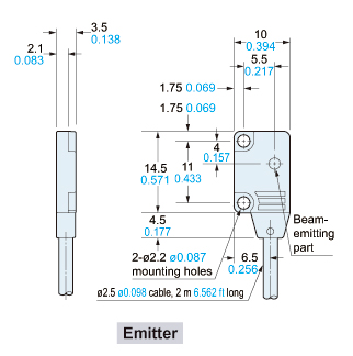
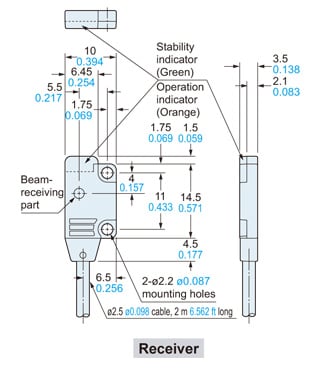
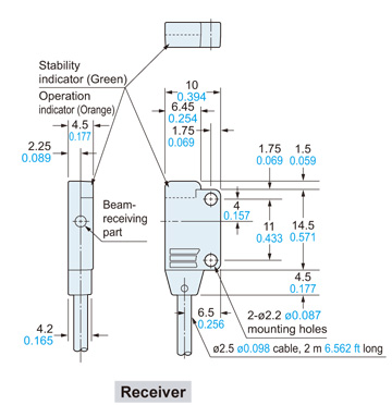
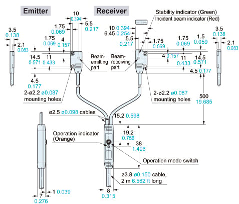
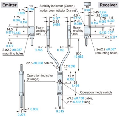
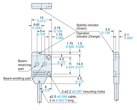
Dimensions
- Unit: mm in
EX-11□ EX-11S□
EX-13□ EX-13S□
EX-19□ EX-19S□
Sensor
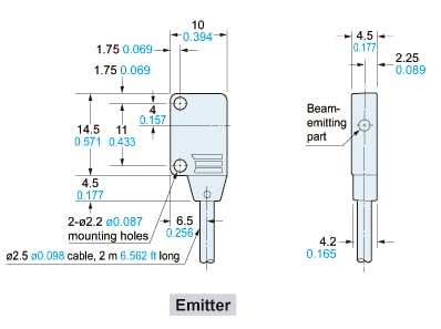
EX-11E□ EX-11SE□
EX-13E□ EX-13SE□
EX-19E□
Sensor
EX-15
EX-17
Sensor
EX-15E
EX-17E
Sensor
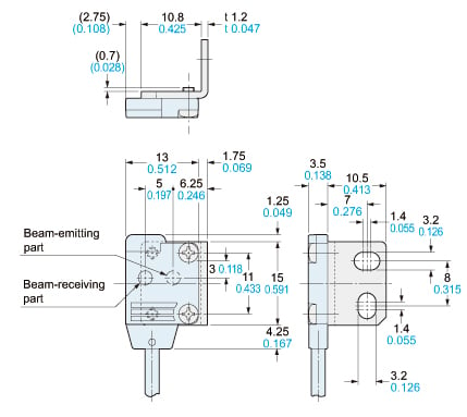
EX-14□
Sensor
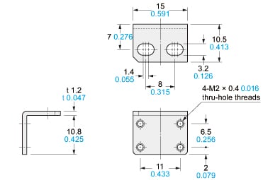
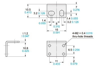
MS-EX10-1
Sensor mounting bracket (Optional)
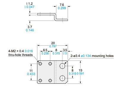
Material:Cold rolled carbon steel (SPCC) (Uni-chrome plated)Two M2 (length 4 mm0.157 in) pan head screws are attached.
Assembly dimensions
Mounting drawing with EX-14□
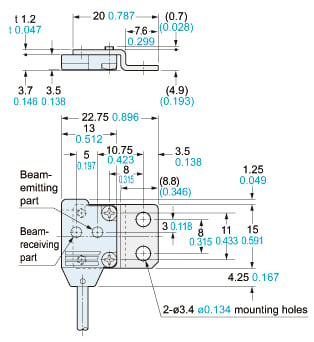
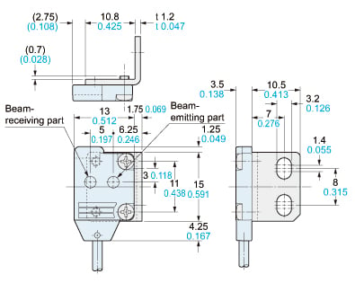
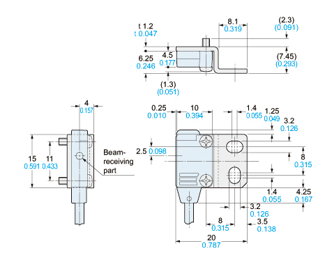
MS-EX10-2
Sensor mounting bracket (Optional)
Material:Cold rolled carbon steel (SPCC) (Uni-chrome plated)Two M2 (length 8 mm0.315 in) pan head screws are attached.
Assembly dimensions
Mounting drawing with EX-11E□ and EX-13E□
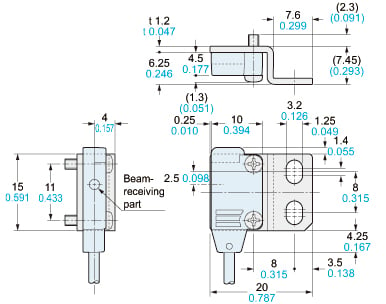
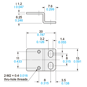
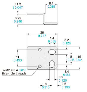
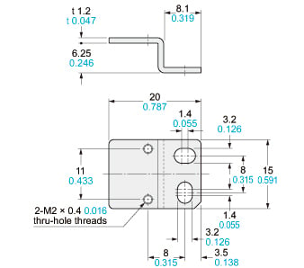
MS-EX10-3
Sensor mounting bracket (Optional)
Material:Cold rolled carbon steel (SPCC) (Uni-chrome plated)Two M2 (length 4 mm0.157 in) pan head screws and two M2 (length 8 mm0.315 in) pan head screws are attached.
Assembly dimensions
Mounting drawing with EX-14□
MS-EX10-11
Sensor mounting bracket (Optional)
Material: Stainless steel (SUS304)Two M2 (length 4 mm0.157 in) pan head screws [stainless steel (SUS304)] are attached.
Assembly dimensions
Mounting drawing with EX-14□
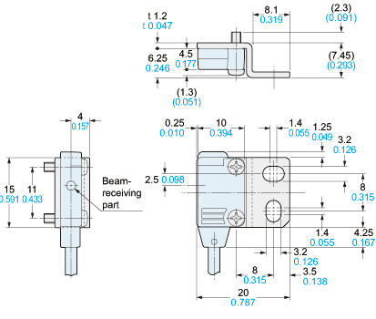
MS-EX10-12
Sensor mounting bracket (Optional)
Material:Stainless steel (SUS304)Two M2 (length 8 mm0.315 in) pan head screws [stainless steel (SUS304)] are attached.
Assembly dimensions
Mounting drawing with EX-11E□ and EX-13E□
MS-EX10-13
Sensor mounting bracket (Optional)
Material:Stainless steel (SUS304)Two M2 (length 4 mm0.157 in) pan head screws [stainless steel (SUS304)] and two M2 (length 8 mm0.315 in) pan head screws [stainless steel (SUS304)] are attached.
Assembly dimensions
Mounting drawing with EX-14□
------------------------------ Tab7 showing ------------------------------
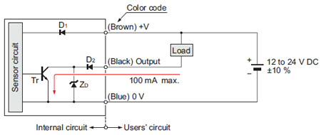
I/O Circuit and Wiring diagrams
EX-11□, EX-11S□, EX-13□, EX-13S□, EX-19□, EX-19S□, EX-14□
NPN output type
I/O circuit diagram
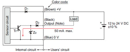
Note:The emitter of the thru-beam type sensor does not incorporate the output.
Symbols・・・
D1: Reverse supply polarity protection diode
D2: Reverse output polarity protection diode
ZD: Surge absorption zener diode
Tr : NPN output transistor
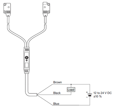
Wiring diagram
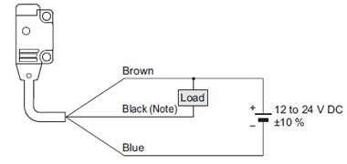
Note:The emitter of the thru-beam type sensor does not incorporate the black wire.
EX-11□-PN, EX-11S□-PN, EX-13□-PN, EX-13S□-PN, EX-19□-PN, EX-19S□-PN, EX-14□-PN
PNP output type
I/O circuit diagram
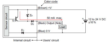
Note:The emitter of the thru-beam type sensor does not incorporate the output.
Symbols・・・
D1: Reverse supply polarity protection diode
D2: Reverse output polarity protection diode
ZD: Surge absorption zener diode
Tr : PNP output transistor
Wiring diagram
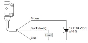
Note:The emitter of the thru-beam type sensor does not incorporate the black wire.
EX-15□, EX-15E□, EX-17□, EX-17E□
NPN output type
I/O circuit diagram
Symbols・・・
D1: Reverse supply polarity protection diode
D2: Reverse output polarity protection diode
ZD: Surge absorption zener diode
Tr : NPN output transistor
Wiring diagram
------------------------------ Tab8 showing ------------------------------
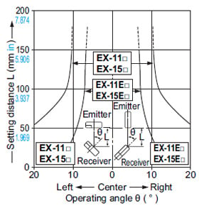
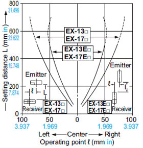
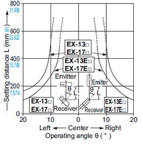
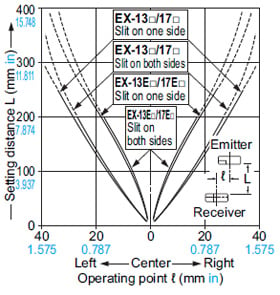
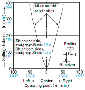
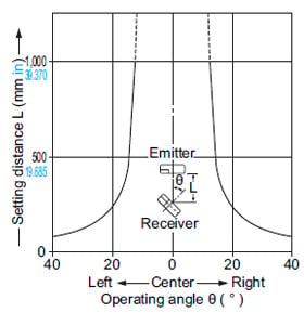
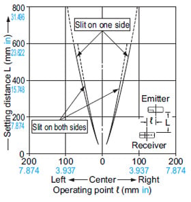
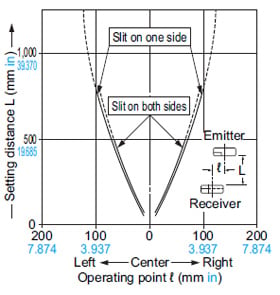
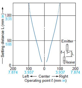
Sensing characteristics
*TYPICAL
EX-11□, EX-11E□, EX-15□, EX-15E□
Thru-beam type
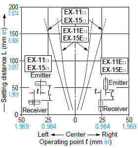
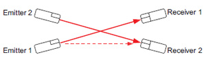
*Optical properties of side sensing types (EX-□E□)
Due to the optical properties of side sensing types, note that sensing may be affected if multiple sensors are positioned in such a way that optical axes intersect as shown in the diagram below.
EX-13□, EX-13E□, EX-17□, EX-17E□
Thru-beam type
EX-19□
Thru-beam type
EX-19E□
Thru-beam type
EX-11S□/EX-11SE□
Thru-beam type
EX-13S□/EX-13SE□
Thru-beam type
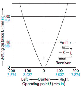
EX-19S□
Thru-beam type
EX-14□
Convergent reflective type
Correlation between lightness and sensing range
The sensing region (typical) is represented by oblique lines in the left figure. However, the sensitivity should be set with enough margin because of slight variation in products.
(Lightness shown on the left may differ slightly from the actual object condition.)
Correlation between material (50 × 50 mm 1.969 × 1.969 in) and sensing range
The bars in the graph indicate the sensing range (typical) for the respective material.
However, there is a slight variation in the sensing range depending on the product.
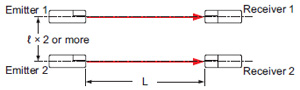
Further, if there is a reflective object (conveyor, etc.) in the background of the sensing object, since it affects the sensing, separate it by more than twice the sensing range shown in the left graph.
------------------------------ Tab9 showing ------------------------------
Mounting
• In case of mounting on tapped holes (Unit: mm in)
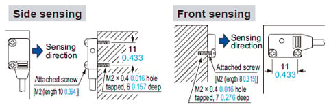
The tightening torque should be 0.2 N·m or less.
• In case of using attached screws and nuts (Unit: mm in)
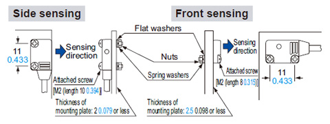
The tightening torque should be 0.2 N·m or less.
Operation mode switch
(EX-15□, EX-15E□, EX-17□ and EX-17E□ only)
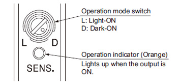
| Switch position | Description |
|---|---|
| Light-ON mode is set when the switch is turned fully clockwise (L side). |
| Dark-ON mode is set when the switch is turned fully counterclockwise (D side). |


Others
- This product has been developed / produced for industrial use only.
- This product is suitable for indoor use only.
- Do not use during the initial transient time (50 ms) after the power supply is switched on.
- Excess bending of the cable or stress applied to the cable may disconnect the internal lead wire.