------------------------------ Tab1 showing ------------------------------
Basic Information
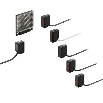
Sensors that are environmentally and user friendly.


UL : Recognition
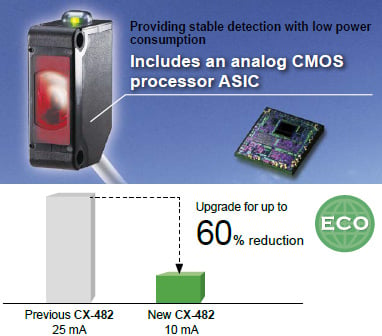
Reducing environmental burdens further
Up to 60% less power consumption
The CX-400 series achieves reductions in power consumption of up to 60%, averaging 44% reduction when upgrading due to its unique design. These sensors reduce carbon emissions and contribute to environmental friendliness.
Contributing to reduced carbon dioxide emissions
Electricity consumed by the CX-400 series has been reduced on average 10.5 mA. Calculating 8 hours/day, 260 days (operating 5 days/week) for a total of 2,080 hours/year leads to:
The CX-400 contributes
Approx. 84.6 t annually in carbon dioxide reductions to the world
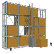
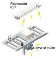
Stronger noise resistance
Stronger inverter countermeasures
The CX-400 has a high noise resistance then its previons model. By incorporating an inverter countermeasure circuit that appropriately shifts with peak wavelength, the sensor now resists high-frequency noise from high-voltage inverter motors and inverter lights more effectively.
Stronger output short-circuit resistance
Stronger inverse wiring connection protection
Strengthening the output circuit inverse polarity protection prevents sensor damage caused by mistaken output or power supply wiring.
Resistant to oil and coolant liquids [ CX-41□/42□/49□ ]
The lens material is made of a strong acrylic that resists the harmful effects of coolants.
These sensors can be used with confidence even around metal processing machine that disperse oil mists. The protection mechanism also conforms to IP67 (IEC).
| Test Oil | JIS Standard | Product Name |
|---|---|---|
| Lubricant | - | Velocity Oil No. 3 |
| Water-insoluble cutting oil | 2-5 | Daphnecut AS-30D |
| 2-11 | Yushiron Oil No.2ac (Note) | |
| Water-soluble cutting oil | W1-1 | Yushiron Lubic HWC68 (Note) |
| W2-1 | Yushiroken S50N (Note) |
1,000 hours; Immersion (depth 0 m); Insulation resistance 20 MΩ/250 V
Note:Yushiron and Yushiroken are registered trademarks of Yushiro Chemical Industry Co., Ltd.
Strongly ethanol resistant [ CX-44□/48□ ]
A strong, ethanol resistant polycarbonate was used for the front and display covers.
Safe even for installing near food processing machinery that disperses ethanol based detergents.
The protection mechanism also conforms to IP67 (IEC).
Caution: Set the CX-48□ so that cleaning liquid will not get on to the attached reflector.

Strong construction to resist water and dust[ CX-400 Series ]
Achieving the IP67 protection rating (IEC), the CX-400 series can be used safely in environments where water and dust are present.
Caution: The sensor may detect water if water splashes on the unit during detection operation.
![Strongly ethanol resistant [CX-44□/48□]](https://tp.industry.panasonic.com/hubfs/pid-corp/products/fasys/sensor/photoelectric/cx-400/images/pic06.jpg)
High Performance
High performance for many applications
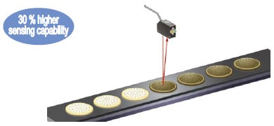
The CX-400 series is capable of stably detecting a minute difference of 0.4 mm 0.016 in (the thickness of a business card) or 10 μm 0.394 mil ultra-thin film, thanks to its unique optics and specialized design of electronic circuits.
Bright red beam spot is useful when confirming a detection position.

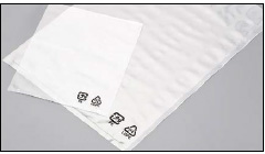
Save
Thoroughly eliminating unnecessary waste, reducing many environmental burdens
The CX-400 series has three different cable length types and uses very simple packaging to reduce waste. The bag is made of polyethylene and does not emit toxic gasses.
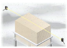
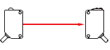
Thru-beam type
Strong infrared beam [CX-412/413]
Remarkable penetrating ability enables applications such as package content detection come into practice.
Note: When utilizing penetrating power in detection, make sure to verify using the actual sensor.
Strong in dust and dirt [CX-412/413]
The infrared light source is strong in dust and dirt compared to the red beam type.
Even the thru-beam type is strong at mutual interference [CX-411]
Two CX-411 sensors, with their red beam light source, can be installed close together by inserting an interference prevention filter.

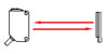
Retroreflective type
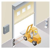
Long sensing range of 5 m 16.404 ft [CX-493]
A long 5 m 16.404 ft sensing range is possible with the red LED type that is easy to align with the beam axis. The sensors can be used for wide automatic door shutters.
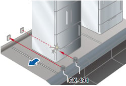
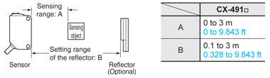
Retroreflective type with polarizing filters [CX-491]
Built-in polarizing filters ensure stable sensing even on a mirror surface object.
Two sensors can be mounted close together [CX-49□/48□]
Up to two sensors can be mounted closely by the automatic interference prevention function.
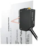
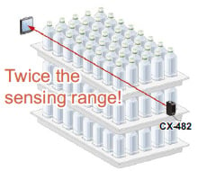
Transparent object sensing type sensor [CX-48□]
Our unique optical system and transparent object sensing circuit provide stable sensing of thinner transparent objects than the conventional models.
Transparent objects detectable with CX-48□ (Typical examples)
| Sensing object | Sensing object size (mm in) | |
|---|---|---|
| Glass sheet | □50 □1.969 | t=0.7 t=0.028 |
| Cylindrical glass | ø50 ø1.969 ℓ =50 ℓ =1.969 | t=1.3 t=0.051 |
| Acrylic board | □50 □1.969 | t=1.0 t=0.039 |
| Styrol (Floppy case) | □50 □1.969 | t=0.9 t=0.035 |
| Food wrapping film | □50 □1.969 | t=10 μm t=0.394 mil |
| Cigarette case film | □50 □1.969 | t=20 μm t=0.787 mil |
| Vinyl bag | □50 □1.969 | t=30 μm t=1.181 mil |
| Pet bottle (500mℓ) | ø66 ø2.598 | |
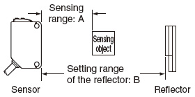
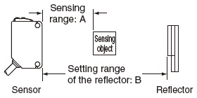
Reflector setting range
CX-481: 300 to 500 mm 11.811 to 19.685 in
CX-482: 1 to 2 m 3.281 to 6.562 ft
CX-483: 500 to 1,000 mm 19.685 to 39.370 in
[with the RF-230 reflector at the optimum condition (Note)]
Each object should pass across the beam at the center between the sensor and the reflector.
ℓ : Length of cylindrical glasses
t : Thickness of sensing object
Note: The optimum condition is defined as the condition in which the sensitivity level is set such that the stability indicator just lights up when the object is absent.
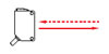
Diffuse reflective type

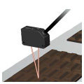
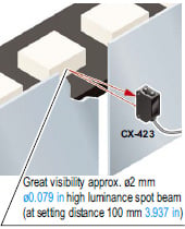
Beam axis alignment made easy with a high luminance spot beam [CX-423]
These sensors have a high luminance red LED spot beam which provides bright visibility enabling the sensing position to be checked at a glance.
Because it achieved small beam spot approx. ø2 mm ø0.079 in at setting distance 100 mm 3.937 in, approx. ø5 mm ø0.197 in at setting distance 200 mm 7.874 in, even the minutest object can be accurately detected.
Reduction of volume adjustment labor [CX-42□]
Because these sensors possess many variations depending on the sensing range, they enable you to make optimal volume adjustment easily.
Two sensors can be mounted close together [CX-42□]
Up to two sensors can be mounted closely by the automatic interference prevention function.
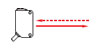
Adjustable range reflective type
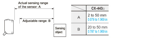
High precision type [CX-441/444]
Can sense height differences as small as 0.4 mm 0.016 in, with hysteresis of 2 % or less
An advanced optical system provides sensing performance that is approx. 2.5 times than conventional models. Even ultra-small differences of 0.4 mm 0.016 in can be detected accurately.

Hardly affected by colors
Both black and white objects can be sensed at the same distances. No adjuster control is needed, even when products of different colors are moving along the production line.
Select from 2 spot diameters as per application
We offer small spot type for detecting minute objects and large spot type capable of sensing objects covered with holes and grooves.
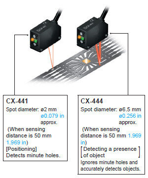
* The CX-444 supports a detection distance of up to 100 mm 3.937 in.
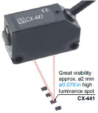
The bright spot makes beam axis alignment easy [CX-44□]
These sensors have a high luminance red spot that provides bright visibility. The sensing position can be checked at a glance.
Because the CX-441 sensor has a small spot beam, at approx. ø2 mm ø0.079 in, even the minutest object can be accurately detected.
Can be used for sensing minute differences [CX-44□]
Equipped with a multirotation adjuster so that even challenging range settings can be handled with ease.
Equipped with automatic interference prevention function [CX-44□]
The automatic interference prevention function prevents mutual interference.
BGS / FGS functions make even the most challenging settings possible! [CX-44□]
The BGS function is best suited for the following case
Background not present
When object and background are separated
Not affected if the background color changes or someone passes behind the conveyor.

The sensor judges that an object is present when light is received at position A of the light-receiving element (2-segment element).
This is useful if the object and background are far apart. The distance adjustment method is the same as the conventional adjustment method for adjustable range reflective type sensors.
The FGS function is best suited for the following case
Background present
When object and background are close together When the object is glossy or uneven
Unaffected by gloss, color or uneven surfaces when sensing objects present on a conveyor belt.
Note: Please use the FGS function together with a conveyor or other background unit.
The sensor judges that an object is present when no light is received at position B of the light-receiving element (2-segment element). Accordingly, even objects that are glossy can be sensed. This is useful if the object and background are close together, or if the object being sensed is glossy.
------------------------------ Tab2 showing ------------------------------


background objects. Uses BGS function.
------------------------------ Tab3 showing ------------------------------
Order guide
Standard type
Thru-beam type
| Type | Appearance | Sensing range | Model No. (Note 1) | Output operation | Emitting element | |
|---|---|---|---|---|---|---|
| NPN output | PNP output | |||||
| 10 m 32.808 ft | CX-411 | CX-411-P | Switchable either Light-ON or Dark-ON | Red LED | |
| Long sensing range | 15 m 49.213 ft | CX-412 | CX-412-P | Infrared LED | ||
| 30 m 98.425 ft | CX-413 | CX-413-P | ||||
Retroreflective type
| Type | Appearance | Sensing range | Model No. (Note 1) | Output operation | Emitting element | |
|---|---|---|---|---|---|---|
| NPN output | PNP output | |||||
| With polarizing filters |
| 3 m 9.843 ft (Note 2) | CX-491 | CX-491-P | Switchable either Light-ON or Dark-ON | Red LED |
| Long sensing range | 5 m 16.404 ft (Note 2) | CX-493 | CX-493-P | |||
| For transparent object sensing | 50 to 500 mm 1.969 to 19.685 in (Note 2) | CX-481 | CX-481-P | Infrared LED | ||
| 50 to 1,000mm 1.969 to 39.37 in (Note 2) | CX-483 | CX-483-P | ||||
| 0.1 to 2 m 0.328 to 6.562 ft (Note 2) | CX-482 | CX-482-P | ||||
Diffuse reflective type
| Type | Appearance | Sensing range | Model No. (Note 1) | Output operation | Emitting element | |
|---|---|---|---|---|---|---|
| NPN output | PNP output | |||||
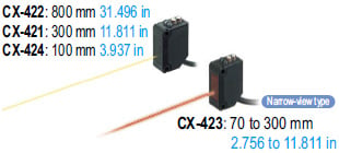
| 100 mm 3.937 in | CX-424 | CX-424-P | Switchable either Light-ON or Dark-ON | Infrared LED | |
| 300 mm 11.811 in | CX-421 | CX-421-P | ||||
| 800 mm 31.496 in | CX-422 | CX-422-P | ||||
| Narrow-view |
| 70 to 300 mm 2.756 to 11.811 in | CX-423 | CX-423-P | Red LED | |
Adjustable range reflective type
| Type | Appearance | Sensing range | Model No. (Note 1) | Output operation | Emitting element | |
|---|---|---|---|---|---|---|
| NPN output | PNP output | |||||
| Small spot |
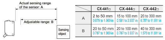
| 2 to 50 mm 0.079 to 1.969 in Adjustable range: 20 to 50 mm 0.787 to 1.969 in | CX-441 | CX-441-P | Switchable either Detection-ON or Detection-OFF | Red LED |
| 2 to 50 mm 0.079 to 1.969 in (Distance setting: 50 mm 1.969 in) | CX-444 | CX-444-P | ||||
| 15 to 100 mm 0.591 to 3.937 in (Distance setting: 100 mm 3.937 in) Adjustable range: 20 to 100 mm 0.787 to 3.937 in | ||||||
| 20 to 300 mm 0.787 to 11.811 in Adjustable range: 40 to 300 mm 1.575 to 11.811 in | CX-442 | CX-442-P | ||||

NOTE: Mounting bracket is not supplied with the sensor. Please select from the range of optional sensor mounting brackets.
Notes:
1)The model No. with "E" shown on the label affixed to the thru-beam type sensor is the emitter, "D" shown on the label is the receiver.
2)
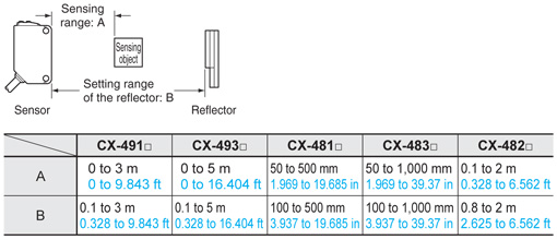
The sensing range of the retroreflective type sensor is specified for the RF-230 reflector. The sensing range represents the actual sensing range of the sensor. The sensing ranges itemized in "A" of the table below may vary depending on the shape of sensing object. Be sure to check the operation with the actual sensing object.
| CX-491□ | CX-493□ | CX-481□ | CX-483□ | CX-482□ | |
|---|---|---|---|---|---|
| A | 0 to 3 m 0 to 9.843 ft | 0 to 5 m 0 to 16.404 ft | 50 to 500 mm 1.969 to 19.685 in | 50 to 1,000 mm 1.969 to 39.37 in | 0.1 to 2 m 0.328 to 6.562 ft |
| B | 0.1 to 3 m 0.328 to 9.843 ft | 0.1 to 5 m 0.328 to 16.404 ft | 100 to 500 mm 3.937 to 19.685 in | 100 to 1,000 mm 3.937 to 39.37 in | 0.8 to 2 m 2.625 to 6.562 ft |
5 m 16.4 ft cable length types
5 m 16.404 ft cable length types (standard: 2 m 6.562 ft, basic: 0.5 m 1.640 in) are available.
When ordering this type, suffix "-C5" for the 5 m 16.404 ft cable length type to the model No.
(Excluding CX-44□ and basic type.)
(e.g.)
5 m 16.404 ft cable length type of CX-411-P is "CX-411-P-C5"
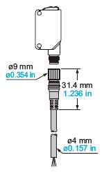
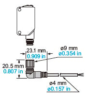
M8 plug-in connector type, M12 pigtailed type
M8 plug-in connector type and M12 pigtailed type are also available.
When ordering this type, suffix "-Z" for the M8 connector type, "-J" for the M12 pigtailed type to the model No.
(Please note that M12 pigtailed type is not available for CX-44□. Excluding basic type.)
(e.g.)
M8 connector type of CX-411-P is "CX-411-P-Z"
M12 pigtailed type of CX-411-P is "CX-411-P-J"
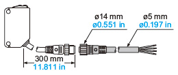
・Mating cables (2 cables are required for the thru-beam type)
| Type | Model No. | Cable length | Description | |
|---|---|---|---|---|
| For M8 plug-in connector type | Straight | CN-24A-C2 | 2 m 6.562 ft | Can be used with all models |
| CN-24A-C5 | 5 m 16.404 ft | |||
| Elbow | CN-24AL-C2 | 2 m 6.562 ft | ||
| CN-24AL-C5 | 5 m 16.404 ft | |||
| For M12 pigtailed type | 2-core | CN-22-C2 | 2 m 6.562 ft | For thru-beam type emitter (2-core) |
| CN-22-C5 | 5 m 16.404 ft | |||
| 4-core | CN-24-C2 | 2 m 6.562 ft | Can be used with all models | |
| CN-24-C5 | 5 m 16.404 ft |
Mating cables
CN-24A-C2
CN-24A-C5
CN-24AL-C2
CN-24AL-C5
CN-22-C2, CN-22-C5
CN-24-C2, CN-24-C5
Package without reflector
NPN output type: CX-491-Y
Table of Model Nos.
Standard type
* Products colored in gray are scheduled to be discontinued.
| Type | Standard type (cable length : 2m 6.562 ft) | 0.5 m 1.640 in cable length types | 5 m 16.4 ft cable length types | M8 plug-in connector type | M12 pigtailed type | ||
|---|---|---|---|---|---|---|---|
| Thru-beam | NPN output | CX-411 | CX-411-C05 | CX-411-C5 | CX-411-Z | CX-411-J | |
| PNP output | CX-411-P | CX-411-P-C05 | CX-411-P-C5 | CX-411-P-Z | CX-411-P-J | ||
| NPN output | CX-412 | CX-412-C05 | CX-412-C5 | CX-412-Z | CX-412-J | ||
| PNP output | CX-412-P | CX-412-P-C05 | CX-412-P-C5 | CX-412-P-Z | CX-412-P-J | ||
| NPN output | CX-413 | CX-413-C05 | CX-413-C5 | CX-413-Z | CX-413-J | ||
| PNP output | CX-413-P | CX-413-P-C05 | CX-413-P-C5 | CX-413-P-Z | CX-413-P-J | ||
| Retroreflective | NPN output | CX-481 | CX-481-C05 | CX-481-C5 | CX-481-Z | CX-481-J | |
| PNP output | CX-481-P | CX-481-P-C05 | CX-481-P-C5 | CX-481-P-Z | CX-481-P-J | ||
| NPN output | CX-482 | CX-482-C05 | CX-482-C5 | CX-482-Z | CX-482-J | ||
| PNP output | CX-482-P | CX-482-P-C05 | CX-482-P-C5 | CX-482-P-Z | CX-482-P-J | ||
| NPN output | CX-483 | CX-483-C05 | CX-483-C5 | CX-483-Z | CX-483-J | ||
| PNP output | CX-483-P | CX-483-P-C05 | CX-483-P-C5 | CX-483-P-Z | CX-483-P-J | ||
| NPN output | CX-491 | CX-491-C05 | CX-491-C5 | CX-491-Z | CX-491-J | ||
| PNP output | CX-491-P | CX-491-P-C05 | CX-491-P-C5 | CX-491-P-Z | CX-491-P-J | ||
| NPN output | CX-493 | CX-493-C05 | CX-493-C5 | CX-493-Z | CX-493-J | ||
| PNP output | CX-493-P | CX-493-P-C05 | CX-493-P-C5 | CX-493-P-Z | CX-493-P-J | ||
| without reflector | NPN output | CX-491-Y | CX-491-C05-Y | CX-491-C5-Y | CX-491-Z-Y | CX-491-J-Y | |
| PNP output | CX-491-P-Y | CX-491-P-C05-Y | CX-491-P-C5-Y | CX-491-P-Z-Y | CX-491-P-J-Y | ||
| NPN output | CX-493-Y | CX-493-C05-Y | CX-493-C5-Y | CX-493-Z-Y | CX-493-J-Y | ||
| PNP output | CX-493-P-Y | CX-493-P-C05-Y | CX-493-P-C5-Y | CX-493-P-Z-Y | CX-493-P-J-Y | ||
| Diffuse reflective | NPN output | CX-421 | CX-421-C05 | CX-421-C5 | CX-421-Z | CX-421-J | |
| PNP output | CX-421-P | CX-421-P-C05 | CX-421-P-C5 | CX-421-P-Z | CX-421-P-J | ||
| NPN output | CX-422 | CX-422-C05 | CX-422-C5 | CX-422-Z | CX-422-J | ||
| PNP output | CX-422-P | CX-422-P-C05 | CX-422-P-C5 | CX-422-P-Z | CX-422-P-J | ||
| NPN output | CX-423 | CX-423-C05 | CX-423-C5 | CX-423-Z | CX-423-J | ||
| PNP output | CX-423-P | CX-423-P-C05 | CX-423-P-C5 | CX-423-P-Z | CX-423-P-J | ||
| NPN output | CX-424 | CX-424-C05 | CX-424-C5 | CX-424-Z | CX-424-J | ||
| PNP output | CX-424-P | CX-424-P-C05 | CX-424-P-C5 | CX-424-P-Z | CX-424-P-J | ||
| Adjustable range reflective | NPN output | CX-441 | - | - | CX-441-Z | - | |
| PNP output | CX-441-P | - | - | CX-441-P-Z | - | ||
| NPN output | CX-442 | - | - | CX-442-Z | - | ||
| PNP output | CX-442-P | - | - | CX-442-P-Z | - | ||
| NPN output | CX-443 | - | - | CX-443-Z | - | ||
| PNP output | CX-443-P | - | - | CX-443-P-Z | - | ||
| NPN output | CX-444 | - | - | CX-444-Z | - | ||
| PNP output | CX-444-P | - | - | CX-444-P-Z | - | ||
Basic type
* Products colored in gray are scheduled to be discontinued.
* The basic type is the only standard specification product with a cable length of 0.5 m 1.640 in.
| Type | Basic type (cable length : 0.5m 1.640 in) | |
|---|---|---|
| Thru-beam | NPN output | CX-411A-C05 |
| CX-411B-C05 | ||
| PNP output | CX-411A-P-C05 | |
| CX-411B-P-C05 | ||
| NPN output | CX-412A-C05 | |
| CX-412B-C05 | ||
| PNP output | CX-412A-P-C05 | |
| CX-412B-P-C05 | ||
| Retroreflective | NPN output | CX-491A-C05-Y |
| CX-491B-C05-Y | ||
| PNP output | CX-491A-P-C05-Y | |
| CX-491B-P-C05-Y | ||
Accessory
RF-230 (Reflector)
------------------------------ Tab4 showing ------------------------------
Option
| Designation | Model No. | Slit size | Sensing range | Min. sensing object | |||
|---|---|---|---|---|---|---|---|
| Slit mask | Sensor | Slit on one side | Slit on both sides | Slit on one side | Slit on both sides | ||
| Round slit mask (For thru-beam type sensor only) | OS-CX-05 | CX-411□ | ø0.5 mm ø0.020 in | 400 mm 15.748 in | 20 mm 0.787 in | ø12 mm ø0.472 in | ø0.5 mm ø0.020 in |
| CX-412□ | 600 mm 23.622 in | 30 mm 1.181 in | |||||
| CX-413□ | 1,200 mm 47.242 in | 60 mm 2.362 in | |||||
| OS-CX-1 | CX-411□ | ø1 mm ø0.039 in | 900 mm 35.433 in | 100 mm 3.937 in | ø12 mm ø0.472 in | ø1 mm ø0.039 in | |
| CX-412□ | 1.35 m 4.429 ft | 150 mm 5.906 in | ø1.5 mm ø0.059 in | ||||
| CX-413□ | 2.7 m 8.857 ft | 300 mm 11.811 in | |||||
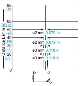
| OS-CX-2 | CX-411□ | ø2 mm ø0.079 in | 2 m 6.562 ft | 400 mm 15.748 in | ø12 mm ø0.472 in | ø2 mm ø0.079 in | |
| CX-412□ | 3 m 9.843 ft | 600 mm 23.622 in | ø3 mm ø0.118 in | ||||
| CX-413□ | 6 m 19.685 ft | 1,200 mm 47.242 in | |||||
| Rectangular slit mask (For thru-beam type sensor only) | OS-CX-05 × 6 | CX-411□ | 0.5 × 6 mm 0.020 × 0.236 in | 2 m 6.562 ft | 400 mm 15.748 in | ø12 mm ø0.472 in | 0.5 × 6 mm 0.020 × 0.236 in |
| CX-412□ | 3 m 9.843 ft | 600 mm 23.622 in | |||||
| CX-413□ | 6 m 19.685 ft | 1,200 mm 47.242 in | |||||
| OS-CX-1 × 6 | CX-411□ | 1 × 6 mm 0.039 × 0.236 in | 3 m 9.843 ft | 1 m 3.281 ft | ø12 mm ø0.472 in | 1 × 6 mm 0.039 × 0.236 in | |
| CX-412□ | 4.5 m 14.764 ft | 1.5 m 4.921 ft | |||||
| CX-413□ | 9 m 29.528 ft | 3 m 9.843 ft | |||||
| OS-CX-2 × 6 | CX-411□ | 2 × 6 mm 0.079 × 0.236 in | 5 m 16.404 ft | 2 m 6.562 ft | ø12 mm ø0.472 in | 2 × 6 mm 0.079 × 0.236 in | |
| CX-412□ | 7.5 m 24.606 ft | 3 m 9.843 ft | |||||
| CX-413□ | 15 m 49.213 ft | 6 m 19.685 ft | |||||
| Model No. (Note 1) | Direction of thru-beam axis | Color of metal | Sensing range | Min. sensing object | |
|---|---|---|---|---|---|
| Interference prevention filter (For CX-411□ only) A set of emitter filter and receiver filter | PF-CX4-V | Horizontal | Light brown | 5 m 16.404 ft (Note 2) | ø12 mm ø0.472 in (Note 2) |
| PF-CX4-H | Vertical | Silver |
Notes:
1) The model No. is not shown on the interference prevention filters. Take care when mounting them on the sensors.
2) Value when attached on both sides.
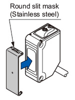
Round slit mask
・OS-CX-□
Fitted on the front face of the sensor with one-touch.
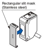
Rectangular slit mask
・OS-CX-□ × 6
Fitted on the front face of the sensor with one-touch.
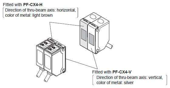
Interference prevention filter
・PF-CX4-H
(Direction of thru-beam axis: Horizontal, Color of metal: Light brown)
・PF-CX4-V
(Direction of thru-beam axis: Vertical, Color of metal: Silver)
Fitted on the front face of the sensor with one-touch.
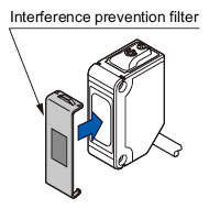
By mounting the interference prevention filters PF-CX4-□, up to two sets of the CX-411□ can be mounted close together.
| Designation | Model No. | Sensing range: A (Note 2) | Setting range of the reflector or reflective tape: B | Min. sensing object | Description | |
|---|---|---|---|---|---|---|
| Sensor | ||||||
| Reflector (Note 1) (For retroreflective type sensor only) | RF-230 | CX-491□ | 3 m 9.843 ft | 0.1 to 3 m 0.328 to 9.843 ft | ø50 mm ø1.969 in | ・Dimensions: W50.3 × H59.3 × D8.3 mm W1.98 × H2.235 × D0.327 in · Mounting hole: ø4.6 mm ø0.181 in · Attached to the retroreflective type sensor except the type without reflector. |
| CX-493□ | 5 m 16.404 ft | 0.1 to 5 m 0.328 to 16.404 ft | ||||
| CX-481□ | 50 to 500 m 1.969 to 19.685 ft | 100 to 500 m 3.937 to 19.685 ft | ||||
| CX-482□ | 0.1 to 2 m 0.328 to 6.562 ft | 0.8 to 2m 2.625 to 6.562 ft | ||||
| CX-483□ | 0.05 to 1 m 0.164 to 3.281 ft | 0.1 to 1m 0.328 to 3.281 ft | ||||
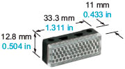
| RF-210 | CX-491□ | 1 m 3.281 ft | 0.1 to 1 m 0.328 to 3.281 ft | ø30 mm ø1.181 in | · Dimensions: W33.3 × H12.8 × D11 mm W1.311 × H0.504 × D0.433 in · Mounting hole: ø3.4 mm ø0.134 in | |
| CX-493□ | 1.5 m 4.921 ft | 0.1 to 1.5 m 0.328 to 4.921 ft | ||||
| CX-481□ | - | - | - | |||
| CX-482□ | 0.1 to 0.6 m 0.328 to 1.969 ft | 0.3 to 0.6 m 0.984 to 1.969 ft | ø30 mm ø1.181 in | |||
| CX-483□ | 0.1 to 0.3 m 0.328 to 0.984 ft | 0.1 to 0.3 m 0.328 to 0.984 ft | ||||
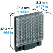
| RF-220 | CX-491□ | 1.5 m 4.921 ft | 0.1 to 1.5 m 0.328 to 4.921 ft | ø35 mm ø1.378 in | ・Dimensions: W35.3 × H42.3 × D8.3 mm W1.390 × H1.665 × D0.327 in · Mounting hole: ø3.6 mm 0.142 in | |
| CX-493□ | 3 m 9.843 ft | 0.1 to 3 m 0.328 to 9.843 ft | ||||
| CX-481□ | 50 to 300 mm 1.969 to 11.811 in | 100 to 300 mm 3.937 to 11.811 in | ||||
| CX-482□ | 0.1 to 1.3 m 0.328 to 4.265 ft | 0.5 to 1.3 m 1.64 to 4.265 ft | ||||
| CX-483□ | 0.1 to 0.7 m 0.328 to 2.297 ft | 0.2 to 0.7 m 0.656 to 2.297 ft | ||||
| Reflective tape (Note 1) (For retroreflective type sensor only) | RF-11 (Note 3) | CX-491□ | 0.5 m 1.640 ft | 0.1 to 0.5 m 0.328 to 1.640 ft | ø30 mm ø1.181 in | · Dimensions: W30 × H8 × D0.7 mm W1.181 × H0.315 × D0.028 in · Ambient temperature: -25 to +50 ºC -13 to +122 °F · Ambient humidity: 35 to 85% RH |
| CX-493□ | 0.8 m 2.625 ft | 0.1 to 0.8 m 0.328 to 2.625 ft | ||||
| CX-481□ | - | - | - | |||
| CX-482□ | - | - | - | |||
| CX-483□ | - | - | - | |||
| RF-12 (Note 3) | CX-491□ | 0.7 m 2.297 ft | 0.1 to 0.7 m 0.328 to 2.297 ft | ø30 mm ø1.181 in | · Dimensions: W30 × H25 × D0.7 mm W1.181 × H0.984 × D0.028 in · Ambient temperature: -25 to +50 ºC -13 to +122 °F · Ambient humidity: 35 to 85% RH | |
| CX-493□ | 1.2 m 3.937 ft | 0.1 to 1.2 m 0.328 to 3.937 ft | ||||
| CX-481□ | - | - | - | |||
| CX-482□ | 0.1 to 0.6 m 0.328 to 1.969 ft | 0.4 to 0.6 m 1.312 to 1.969 ft | ø30 mm ø1.181 in | |||
| CX-483□ | - | - | - | |||
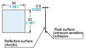
| RF-13 | CX-491□ | 0.5 m 1.64 ft | 0.2 to 0.5 m 0.656 to 1.64 ft | ø30 mm ø1.181 in | · Dimensions: W30 × H30 × D0.5 mm W1.181 × H1.181 × D0.020 in · Ambient temperature: -25 to +55 ºC -13 to +131 °F · Ambient humidity: 35 to 85% RH | |
| CX-493□ | - | - | - | |||
| CX-481□ | - | - | - | |||
| CX-482□ | - | - | - | |||
| CX-483□ | - | - | - | |||
Notes:
1) Be sure to align the beam axis when mounting the sensor and reflector or reflective tape. Use of the RF-210 reflector or RF-11 reflective tape requires more precise adjustment than when the RF-230 reflector supplied with the product is used. Mount the reflector / reflective tape in such a way that the sensor angle can be adjusted in a wide range. For the sensor angle adjustment and reflector / reflective tape position adjustment, refer to "PRECAUTIONS FOR PROPER USE".
2) Sensing range A may vary depending on the shape of the sensing object. Be sure to check the operation with the actual sensing object.
3) Do not press the reflective tape RF-11 and RF-12 strongly because they have soft surfaces. The internal prism may be crushed and the reflection distance may be reduced. Also, do not cut the tape before use. Performance will not be maintained.
Reflector
Reflective tape
| Designation | Model No. | Description | |
|---|---|---|---|
| Reflector mounting bracket | MS-RF21-1 | Protective mounting bracket for RF-210 It protects the reflector from damage and maintains alignment. | |
| MS-RF22 | For RF-220 | ||
| MS-RF23 | For RF-230 | ||
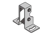
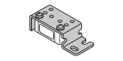
| Sensor mounting bracket (Note 1) | MS-CX2-1 | Foot angled mounting bracket It can also be used for mounting RF-210. | The thru-beam type sensor needs two brackets. |
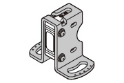
| MS-CX2-2 | Foot biangled mounting bracket It can also be used for mounting RF-210. | ||
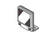
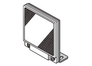
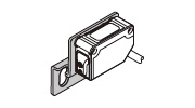
| MS-CX2-4 | Protective mounting bracket | ||
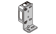
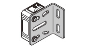
| MS-CX2-5 | Back biangled mounting bracket | ||
| MS-CX-3 | Back angled mounting bracket | ||
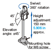
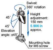
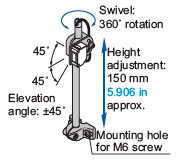
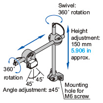
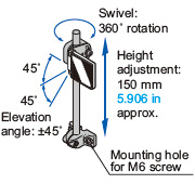
| Universal sensor mounting stand | MS-AJ1 | Horizontal mounting type | Basic assembly |
| MS-AJ2 | Vertical mounting type | ||
| MS-AJ1-A | Horizontal mounting type | Lateral arm assembly | |
| MS-AJ2-A | Vertical mounting type | ||
| MS-AJ1-M | Horizontal mounting type | Assembly for refl ector | |
| MS-AJ2-M | Vertical mounting type | ||
Notes: The plug-in connector type sensor does not allow use of some sensor mounting brackets because of the protrusion of the connector.
Reflector mounting bracket
・MS-RF21-1
Two M3 (length 12 mm0.472 in) screws with washers are attached.
・MS-RF22
Two M3 (length 8 mm0.315 in) screws with washers are attached.
・MS-RF23
Two M4 (length 10 mm0.394 in) screws with washers are attached.
Sensor mounting bracket
・MS-CX2-1
Two M3 (length 12 mm0.472 in) screws with washers are attached.
・MS-CX2-2
Two M3 (length 12 mm0.472 in) screws with washers are attached.
・MS-CX2-4
Two M3 (length 14 mm0.551 in) screws with washers are attached.
・MS-CX2-5
Two M3 (length 12 mm0.472 in) screws with washers are attached.
・MS-CX-3
Two M3 (length 12 mm0.472 in) screws with washers are attached.
Universal sensor mounting stand
・MS-AJ1
・MS-AJ1-A
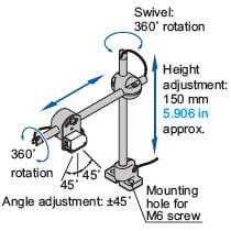
With the lateral arm, the sensor can sense from above a production line.Forward / back adjustment: 130 mm5.118 inapprox.
・MS-AJ1-M
・MS-AJ2
・MS-AJ2-A
With the lateral arm, the sensor can sense from above a production line. Forward / back adjustment: 130 mm5.118 inapprox.
・MS-AJ2-M
Recommended e-CON connector
Manufactured by 3M Japan Limited
Adapted connector : 37104-3122-000 FL
Please refer to "Introducing the 3M™ mini-clamp connector" for details.
------------------------------ Tab5 showing ------------------------------
Specifications
Standard type
| Type | Thru-beam | |||
|---|---|---|---|---|
| Long sensing range | ||||
| Model No. | NPN output | CX-411 | CX-412 | CX-413 |
| PNP output | CX-411-P | CX-412-P | CX-413-P | |
| Applicable regulations and certifications | CE Marking (EMC Directive, RoHS Directive), UKCA Marking (EMC Regulations, RoHS Regulations), UL Recognition Certification | |||
| Sensing range | 10 m 32.808 ft | 15 m 49.213 ft | 30 m 98.425 ft | |
| Sensing object | ø12 mm ø0.472 in or more opaque object (Note 4) | |||
| Hysteresis | - | |||
| Repeatability (perpendicular to sensing axis) | 0.5 mm 0.020 in or less | |||
| Supply voltage | 12 to 24 V DC ± 10 % Ripple P-P 10 % or less | |||
| Current consumption | Emitter: 15 mA or less Receiver: 10 mA or less | Emitter: 20 mA or less Receiver: 10 mA or less | Emitter: 25 mA or less Receiver: 10 mA or less | |
| Output | <NPN output type> NPN open-collector transistor ・Maximum sink current: 100 mA ・Applied voltage: 30 V DC or less (between output and 0 V) ・Residual voltage: 2 V or less (at 100 mA sink current) 1 V or less (at 16 mA sink current) <PNP output type> PNP open-collector transistor ・Maximum source current: 100 mA ・Applied voltage: 30 V DC or less (between output and +V) ・Residual voltage: 2 V or less (at 100 mA source current) 1 V or less (at 16 mA source current) | |||
| Output operation | Switchable either Light-ON or Dark-ON | |||
| Short-circuit protection | Incorporated | |||
| Response time | 1 ms or less | 2 ms or less | ||
| Operation indicator | Orange LED (lights up when the output is ON) (incorporated on the receiver for thru-beam type) | |||
| Stability indicator | Green LED (lights up under stable light received condition or stable dark condition) (incorporated on the receiver for thru-beam type) | |||
| Power indicator | Green LED (lights up when the power is ON) (incorporated on the emitter) | |||
| Sensitivity adjuster | Continuously variable adjuster (incorporated on the receiver for thru-beam type) | |||
| Automatic interference prevention function | Two units of sensors can be mounted close together with interference prevention filters. (Sensing range: 5 m 16.404 ft) | - | ||
| Protection | IP67 (IEC) | |||
| Ambient temperature | - 25 to +55 ℃ -13 to +131 ℉ (No dew condensation or icing allowed ), Storage: -30 to +70 ℃ -22 to +158 ℉ | |||
| Ambient humidity | 35 to 85 % RH, Storage: 35 to 85 % RH | |||
| Ambient illuminance | Incandescent light: 3,000 lx or less at the light-receiving face | |||
| Voltage withstandability | 1,000 V AC for one min. between all supply terminals connected together and enclosure | |||
| Insulation resistance | 20 MΩ, or more, with 250 V DC megger between all supply terminals connected together and enclosure | |||
| Vibration resistance | 10 to 500 Hz frequency, 1.5 mm 0.059 in amplitude (10 G max.) in X, Y and Z directions for two hours each | |||
| Shock resistance | 500 m/s2 acceleration (50 G approx.) in X, Y and Z directions three times each | |||
| Emitting element (modulated) | Red LED | Infrared LED | ||
| Peak emission wavelength | 680 nm 0.027 mil | 870 nm 0.034 mil | 850 nm 0.033 mil | |
| Material | Enclosure: PBT (polybutylene terephthalate), Lens: acrylic (CX-48□: polycarbonate), Indicator cover: acrylic (CX-48□: polycarbonate) | |||
| Cable | 0.2 mm2 3-core (thru-beam type emitter: 2-core) cabtyre cable, 2 m 6.562 ft long | |||
| Cable extension | Extension up to total 100 m 328.084 ft is possible with 0.3 mm2, or more, cable (thru-beam type: both emitter and receiver). | |||
| Weight | Net weight | Emitter: 45 g approx., Receiver: 50 g approx. | ||
| Gross weight | 100 g approx. | |||
| Accessory | - | |||
| Type | Retroreflective | |||||
|---|---|---|---|---|---|---|
| With polarizing filters | Long sensing range | For transparent object sensing | ||||
| Model No. | NPN output | CX-491 | CX-493 | CX-481 | CX-483 | CX-482 |
| PNP output | CX-491-P | CX-493-P | CX-481-P | CX-483-P | CX-482-P | |
| Applicable regulations and certifications | CE Marking (EMC Directive, RoHS Directive), UKCA Marking (EMC Regulations, RoHS Regulations), UL Recognition Certification | |||||
| Sensing range | 3 m 9.843 ft (Note 2) | 5 m 16.404 ft (Note 2) | 50 to 500 mm 1.969 to 19.685 in (Note 2) | 50 to 1,000mm 1.969 to 39.37 in (Note 2) | 0.1 to 2 m 0.328 to 6.562 ft (Note 2) | |
| Sensing object | ø50 mm ø1.969 in or more opaque, translucent or specular object (Note 2, 5) | ø50 mm ø1.969 in or more opaque or translucent object (Note 2, 5) | ø50 mm ø1.969 in or more transparent, translucent or opaque object (Note 2, 5) | |||
| Hysteresis | - | |||||
| Repeatability (perpendicular to sensing axis) | 0.5 mm 0.020 in or less | |||||
| Supply voltage | 12 to 24 V DC ± 10 % Ripple P-P 10 % or less | |||||
| Current consumption | 13 mA or less | 10 mA or less | ||||
| Output | <NPN output type> NPN open-collector transistor ・Maximum sink current: 100 mA ・Applied voltage: 30 V DC or less (between output and 0 V) ・Residual voltage: 2 V or less (at 100 mA sink current) 1 V or less (at 16 mA sink current) <PNP output type> PNP open-collector transistor ・Maximum source current: 100 mA ・Applied voltage: 30 V DC or less (between output and +V) ・Residual voltage: 2 V or less (at 100 mA source current) 1 V or less (at 16 mA source current) | |||||
| Output operation | Switchable either Light-ON or Dark-ON | |||||
| Short-circuit protection | Incorporated | |||||
| Response time | 1 ms or less | |||||
| Operation indicator | Orange LED (lights up when the output is ON) (incorporated on the receiver for thru-beam type) | |||||
| Stability indicator | Green LED (lights up under stable light received condition or stable dark condition) (incorporated on the receiver for thru-beam type) | |||||
| Power indicator | - | |||||
| Sensitivity adjuster | Continuously variable adjuster (incorporated on the receiver for thru-beam type) | |||||
| Automatic interference prevention function | Incorporated (Two units of sensors can be mounted close together.) | |||||
| Protection | IP67 (IEC) | |||||
| Ambient temperature | - 25 to +55 ℃ -13 to +131 ℉ (No dew condensation or icing allowed ), Storage: -30 to +70 ℃ -22 to +158 ℉ | |||||
| Ambient humidity | 35 to 85 % RH, Storage: 35 to 85 % RH | |||||
| Ambient illuminance | Incandescent light: 3,000 lx or less at the light-receiving face | |||||
| Voltage withstandability | 1,000 V AC for one min. between all supply terminals connected together and enclosure | |||||
| Insulation resistance | 20 MΩ, or more, with 250 V DC megger between all supply terminals connected together and enclosure | |||||
| Vibration resistance | 10 to 500 Hz frequency, 1.5 mm 0.059 in amplitude (10 G max.) in X, Y and Z directions for two hours each | |||||
| Shock resistance | 500 m/s2 acceleration (50 G approx.) in X, Y and Z directions three times each | |||||
| Emitting element (modulated) | Red LED | Infrared LED | ||||
| Peak emission wavelength | 680 nm 0.027 mil | 650 nm 0.026 mil | 870 nm 0.034 mil | |||
| Material | Enclosure: PBT (polybutylene terephthalate), Lens: acrylic (CX-48□: polycarbonate), Indicator cover: acrylic (CX-48□: polycarbonate) | |||||
| Cable | 0.2 mm2 3-core (thru-beam type emitter: 2-core) cabtyre cable, 2 m 6.562 ft long | |||||
| Cable extension | Extension up to total 100 m 328.084 ft is possible with 0.3 mm2, or more, cable (thru-beam type: both emitter and receiver). | |||||
| Weight | Net weight | 50 g approx. | ||||
| Gross weight | 80 g approx. | |||||
| Accessory | RF-230 (Reflector): 1 pc. | |||||
| Type | Diffuse reflective | ||||
|---|---|---|---|---|---|
| Narrow-view | |||||
| Model No. | NPN output | CX-424 | CX-421 | CX-422 | CX-423 |
| PNP output | CX-424-P | CX-421-P | CX-422-P | CX-423-P | |
| Applicable regulations and certifications | CE Marking (EMC Directive, RoHS Directive), UKCA Marking (EMC Regulations, RoHS Regulations), UL Recognition Certification | ||||
| Sensing range | 100 mm 3.937 in (Note 3) | 300 mm 11.811 in (Note 3) | 800 mm 31.496 in (Note 3) | 70 to 300 mm 2.756 to 11.811 in (Note3) | |
| Sensing object | Opaque, translucent or transparent object (Note 5) | Opaque, translucent or transparent object (Note 5) (Min. sensing object: ø0.5 mm ø0.020 in copper wire) | |||
| Hysteresis | 15 % or less of operation distance (Note 3) | ||||
| Repeatability (perpendicular to sensing axis) | 1 mm 0.039 in or less | 0.5 mm 0.020 in or less | |||
| Supply voltage | 12 to 24 V DC ± 10 % Ripple P-P 10 % or less | ||||
| Current consumption | 13 mA or less | 15 mA or less | |||
| Output | <NPN output type> NPN open-collector transistor ・Maximum sink current: 100 mA ・Applied voltage: 30 V DC or less (between output and 0 V) ・Residual voltage: 2 V or less (at 100 mA sink current) 1 V or less (at 16 mA sink current) <PNP output type> PNP open-collector transistor ・Maximum source current: 100 mA ・Applied voltage: 30 V DC or less (between output and +V) ・Residual voltage: 2 V or less (at 100 mA source current) 1 V or less (at 16 mA source current) | ||||
| Output operation | Switchable either Light-ON or Dark-ON | ||||
| Short-circuit protection | Incorporated | ||||
| Response time | 1 ms or less | ||||
| Operation indicator | Orange LED (lights up when the output is ON) (incorporated on the receiver for thru-beam type) | ||||
| Stability indicator | Green LED (lights up under stable light received condition or stable dark condition) (incorporated on the receiver for thru-beam type) | ||||
| Power indicator | - | ||||
| Sensitivity adjuster | Continuously variable adjuster (incorporated on the receiver for thru-beam type) | ||||
| Automatic interference prevention function | Incorporated (Two units of sensors can be mounted close together.) | ||||
| Protection | IP67 (IEC) | ||||
| Ambient temperature | - 25 to +55 ℃ -13 to +131 ℉ (No dew condensation or icing allowed ), Storage: -30 to +70 ℃ -22 to +158 ℉ | ||||
| Ambient humidity | 35 to 85 % RH, Storage: 35 to 85 % RH | ||||
| Ambient illuminance | Incandescent light: 3,000 lx or less at the light-receiving face | ||||
| Voltage withstandability | 1,000 V AC for one min. between all supply terminals connected together and enclosure | ||||
| Insulation resistance | 20 MΩ, or more, with 250 V DC megger between all supply terminals connected together and enclosure | ||||
| Vibration resistance | 10 to 500 Hz frequency, 1.5 mm 0.059 in amplitude (10 G max.) in X, Y and Z directions for two hours each | ||||
| Shock resistance | 500 m/s2 acceleration (50 G approx.) in X, Y and Z directions three times each | ||||
| Emitting element (modulated) | Infrared LED | Red LED | |||
| Peak emission wavelength | 860 nm 0.034 mil | 645 nm 0.025 mil | |||
| Material | Enclosure: PBT (polybutylene terephthalate), Lens: acrylic (CX-48□: polycarbonate), Indicator cover: acrylic (CX-48□: polycarbonate) | ||||
| Cable | 0.2 mm2 3-core (thru-beam type emitter: 2-core) cabtyre cable, 2 m 6.562 ft long | ||||
| Cable extension | Extension up to total 100 m 328.084 ft is possible with 0.3 mm2, or more, cable (thru-beam type: both emitter and receiver). | ||||
| Weight | Net weight | 50 g approx. | |||
| Gross weight | 60 g approx. | ||||
| Accessory | - | ||||
Notes:
1) Where measurement conditions have not been specified precisely, the conditions used were an ambient temperature of +23 ℃ +73.4 ℉.
2) The sensing range and the sensing object of the retroreflective type sensor are specifi ed for the RF-230 reflector. The sensing range represents the actual sensing range of the sensor. The sensing range: A of the table below may vary depending on the shape of sensing object. Be sure to check the operation with the actual sensing object.
3) The sensing range and hysteresis of the diffuse reflective type sensor are specified for white non-glossy paper (200 x 200 mm 7.874 x 7.874 in) as the object.
4) If slit masks (optional) are fitted, an object of ø0.5 mm ø0.020 in (using round slit mask) can be detected.
5) Make sure to confirm detection with an actual sensor before use.
| Type | Adjustable range reflective | |||
|---|---|---|---|---|
| Small spot | ||||
| Model No. | NPN output | CX-441 | CX-444 | CX-442 |
| PNP output | CX-441-P | CX-444-P | CX-442-P | |
| Applicable regulations and certifications | CE Marking (EMC Directive, RoHS Directive), UKCA Marking (EMC Regulations, RoHS Regulations), UL Recognition Certification | |||
| Adjustable range (Note 2) | 20 to 50 mm 0.787 to 1.969 in | 20 to 100 mm 0.787 to 3.937 in | 40 to 300 mm 1.575 to 11.811 in | |
| Sensing range (with white non-glossy paper) | 2 to 50 mm 0.079 to 1.969 in | 2 to 50 mm 0.079 to 1.969 in (Distance setting: 50 mm 1.969 in) 15 to 100 mm 0.591 to 3.937 in (Distance setting: 100 mm 3.937 in) | 20 to 300 mm 0.787 to 11.811 in | |
| Hysteresis | 2 % or less of operation distance (with white non-glossy paper) | 5 % or less of operation distance (with white non-glossy paper) | ||
| Repeatability | Along sensing axis: 1 mm 0.039 in or less, Perpendicular to sensing axis: 0.2 mm 0.008 in or less (with white non-glossy paper) | |||
| Supply voltage | 12 to 24 V DC ± 10 % Ripple P-P 10 % or less | |||
| Current consumption | 20 mA or less | |||
| Output | <NPN output type> NPN open-collector transistor ・Maximum sink current: 100 mA ・Applied voltage: 30 V DC or less (between output and 0 V) ・Residual voltage: 2 V or less (at 100 mA sink current) 1 V or less (at 16 mA sink current) <PNP output type> PNP open-collector transistor ・Maximum source current: 100 mA ・Applied voltage: 30 V DC or less (between output and +V) ・Residual voltage: 2 V or less (at 100 mA source current) 1 V or less (at 16 mA source current) | |||
| Output operation | Switchable either Detection-ON or Detection-OFF | |||
| Short-circuit protection | Incorporated | |||
| Response time | 1 ms or less | |||
| Operation indicator | Orange LED (lights up when the output is ON) | |||
| Stability indicator | Green LED (lights up under stable operating condition) | |||
| Distance adjuster | Multirotation mechanical adjuster | |||
| Sensing mode | BGS / FGS functions switchable with wiring of sensing mode selection input | |||
| Automatic interference prevention function (Note 3) | Incorporated | |||
| Protection | IP67 (IEC) | |||
| Ambient temperature | -25 to +55 ℃ -13 to +131 ℉ (No dew condensation or icing allowed ), Storage: -30 to +70 ℃ -22 to +158 ℉ | |||
| Ambient humidity | 35 to 85 % RH, Storage: 35 to 85 % RH | |||
| Ambient illuminance | Incandescent light: 3,000 lx or less at the light-receiving face | |||
| EMC | EN 60947-5-2 | |||
| Voltage withstandability | 1,000 V AC for one min. between all supply terminals connected together and enclosure | |||
| Insulation resistance | 20 MΩ, or more, with 250 V DC megger between all supply terminals connected together and enclosure | |||
| Vibration resistance | 10 to 500 Hz frequency, 3 mm 0.118 in double amplitude (20 G max.) in X, Y and Z directions for two hours each | |||
| Shock resistance | 500 m/s2 acceleration (50 G approx.) in X, Y and Z directions three times each | |||
| Emitting element | Red LED (Peak emission wavelength: 650 nm 0.026 mil, modulated) | |||
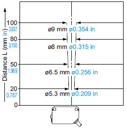
| Spot diameter | ø2 mm ø0.079 in approx. (at 50 mm 1.969 in distance) | ø9 mm ø0.354 in approx. (at 100 mm 3.937 in distance) | ø15 mm ø0.591 in approx. (at 300 mm 11.811 in distance) | |
| Material | Enclosure: PBT (Polybutylene terephthalate), Front cover: Polycarbonate, Indicator cover: Polycarbonate | |||
| Cable | 0.2 mm2 4-core cabtyre cable, 2 m 6.562 ft long | |||
| Cable extension | Extension up to total 100 m 328.084 ft is possible with 0.3 mm2, or more, cable. | |||
| Weight | Net weight: 55 g approx., Gross weight: 65 g approx. | |||
Notes:
1) Where measurement conditions have not been specified precisely, the conditions used were an ambient temperature of +23 ℃ +73.4 ℉.
2) The adjustable range stands for the maximum sensing range which can be set with the distance adjuster. The sensor can detect an object 2 mm 0.079 in [CX-444(-P): 15 mm 0.591 in, CX-442(-P): 20 mm 0.787 in], or more, away.
3) Note that detection may be unstable depending on the mounting conditions or the sensing object. In the state that this product is mounted, be sure to check the operation with the actual sensing object.
Discontinued products
Basic type
| Type | Thru-beam | ||||
|---|---|---|---|---|---|
| Small spot | Long sensing range | ||||
| Light-ON | Dark-ON | Light-ON | Dark-ON | ||
| Model No. | NPN output | CX-411A-C05 | CX-411B-C05 | CX-412A-C05 | CX-412B-C05 |
| PNP output | CX-411A-P-C05 | CX-411B-P-C05 | CX-412A-P-C05 | CX-412B-P-C05 | |
| CE marking directive compliance | EMC Directive, RoHS Directive | ||||
| Sensing range | 10 m 32.808 ft | 15 m 49.213 ft | |||
| Sensing object | ø12 mm ø0.472 in or more opaque object (Note 3) | ||||
| Hysteresis | - | ||||
| Repeatability (perpendicular to sensing axis) | 0.5 mm 0.020 in or less | ||||
| Supply voltage | 12 to 24 V DC ±10 % Ripple P-P 10 % or less | ||||
| Current consumption | Emitter: 15 mA or less Receiver: 10 mA or less | Emitter: 20 mA or less Receiver: 10 mA or less | |||
| Output | <NPN output type> NPN open-collector transistor ・Maximum sink current: 100 mA ・Applied voltage: 30 V DC or less (between output and 0 V) ・Residual voltage: 2 V or less (at 100 mA sink current) 1 V or less (at 16 mA sink current) <PNP output type> PNP open-collector transistor ・Maximum source current: 100 mA ・Applied voltage: 30 V DC or less (between output and +V) ・Residual voltage: 2 V or less (at 100 mA source current) 1 V or less (at 16 mA source current) | ||||
| Short-circuit protection | Incorporated | ||||
| Response time | 1 ms or less | ||||
| Operation indicator | Orange LED (lights up when the output is ON) (incorporated on the receiver for thru-beam type) | ||||
| Stability indicator | Green LED (lights up under stable light received condition or stable dark condition) (incorporated on the receiver for thru-beam type) | ||||
| Power indicator | Green LED (lights up when the power is ON) (incorporated on the emitter) | ||||
| Sensitivity adjuster | - | ||||
| Automatic interference prevention function | Two units of sensors can be mounted close together with interference prevention filters. (Sensing range: 5 m 16.404 ft) | - | |||
| Protection | IP67 (IEC) | ||||
| Ambient temperature | -25 to +55 ℃ -13 to +131 ℉ (No dew condensation or icing allowed), Storage: -30 to +70 ℃ -22 to +158 ℉ | ||||
| Ambient humidity | 35 to 85 % RH, Storage: 35 to 85 % RH | ||||
| Ambient illuminance | Incandescent light: 3,000 lx or less at the light-receiving face | ||||
| EMC | EN 60947-5-2 | ||||
| Voltage withstandability | 1,000 V AC for one min. between all supply terminals connected together and enclosure | ||||
| Insulation resistance | 20 MΩ, or more, with 250 V DC megger between all supply terminals connected together and enclosure | ||||
| Vibration resistance | 10 to 500 Hz frequency, 1.5 mm 0.059 in double amplitude (10 G max.) in X, Y and Z directions for two hours each | ||||
| Shock resistance | 500 m/s2 acceleration (50 G approx.) in X, Y and Z directions three times each | ||||
| Emitting element (modulated) | Red LED | Infrared LED | |||
| Peak emission wavelength | 680 nm 0.027 mil | 870 nm 0.034 mil | |||
| Material | 0.2 mm2 3-core (thru-beam type emitter: 2-core) cabtyre cable, 0.5 m 1.640 ft long | ||||
| Cable | 0.2 mm2 4-core cabtyre cable, 2 m 6.562 ft long | ||||
| Cable extension | Extension up to total 100 m 328.084 ft is possible with 0.3 mm2, or more, cable (thru-beam type: both emitter and receiver) | ||||
| Weight | Net | Emitter: 20 g approx., Receiver: 20 g approx. | |||
| Gross | 50 g approx. | ||||
| Type | Retroreflective | ||
|---|---|---|---|
| With polarizing filters | |||
| Light-ON | Dark-ON | ||
| Model No. | NPN output | CX-491A-C05-Y | CX-491B-C05-Y |
| PNP output | CX-491A-P-C05-Y | CX-491B-P-C05-Y | |
| CE marking directive compliance | EMC Directive, RoHS Directive | ||
| Sensing range | 3 m 9.843 ft (Note 2) | ||
| Sensing object | ø50 mm ø1.969 in or more transparent, translucent or opaque object (Note 2, 4) | ||
| Hysteresis | - | ||
| Repeatability (perpendicular to sensing axis) | 0.5 mm 0.020 in or less | ||
| Supply voltage | 12 to 24 V DC ±10 % Ripple P-P 10 % or less | ||
| Current consumption | 13 mA or less | ||
| Output | <NPN output type> NPN open-collector transistor ・Maximum sink current: 100 mA ・Applied voltage: 30 V DC or less (between output and 0 V) ・Residual voltage: 2 V or less (at 100 mA sink current) 1 V or less (at 16 mA sink current) <PNP output type> PNP open-collector transistor ・Maximum source current: 100 mA ・Applied voltage: 30 V DC or less (between output and +V) ・Residual voltage: 2 V or less (at 100 mA source current) 1 V or less (at 16 mA source current) | ||
| Short-circuit protection | Incorporated | ||
| Response time | 1 ms or less | ||
| Operation indicator | Orange LED (lights up when the output is ON) (incorporated on the receiver for thru-beam type) | ||
| Stability indicator | Green LED (lights up under stable light received condition or stable dark condition) (incorporated on the receiver for thru-beam type) | ||
| Power indicator | Green LED (lights up when the power is ON) (incorporated on the emitter) | ||
| Sensitivity adjuster | - | ||
| Automatic interference prevention function | Incorporated (Two units of sensors can be mounted close together.) | ||
| Protection | IP67 (IEC) | ||
| Ambient temperature | -25 to +55 ℃ -13 to +131 ℉ (No dew condensation or icing allowed), Storage: -30 to +70 ℃ -22 to +158 ℉ | ||
| Ambient humidity | 35 to 85 % RH, Storage: 35 to 85 % RH | ||
| Ambient illuminance | Incandescent light: 3,000 lx or less at the light-receiving face | ||
| EMC | EN 60947-5-2 | ||
| Voltage withstandability | 1,000 V AC for one min. between all supply terminals connected together and enclosure | ||
| Insulation resistance | 20 MΩ, or more, with 250 V DC megger between all supply terminals connected together and enclosure | ||
| Vibration resistance | 10 to 500 Hz frequency, 1.5 mm 0.059 in double amplitude (10 G max.) in X, Y and Z directions for two hours each | ||
| Shock resistance | 500 m/s2 acceleration (50 G approx.) in X, Y and Z directions three times each | ||
| Emitting element (modulated) | Red LED | ||
| Peak emission wavelength | 680 nm 0.027 mil | ||
| Material | 0.2 mm2 3-core (thru-beam type emitter: 2-core) cabtyre cable, 0.5 m 1.640 ft long | ||
| Cable | 0.2 mm2 4-core cabtyre cable, 2 m 6.562 ft long | ||
| Cable extension | Extension up to total 100 m 328.084 ft is possible with 0.3 mm2, or more, cable (thru-beam type: both emitter and receiver) | ||
| Weight | Net | 20 g approx. | |
| Gross | 30 g approx. | ||
Notes:
1) Where measurement conditions have not been specified precisely, the conditions used were an ambient temperature of +23 ℃ +73.4 ℉.
2) The sensing range and the sensing object of the retroreflective type sensor are specified for the RF-230 reflector (optional). The sensing range represents the actual sensing range of the sensor. The sensing range: A of the table below may vary depending on the shape of sensing object. Be sure to check the operation with the actual sensing object.
3) If slit masks (optional) are fitted, an object of ø0.5 mm ø0.020 in (using round slit mask) can be detected.
4) Make sure to confirm detection with an actual sensor before use.
Standard type
| Type | Adjustable range reflective | |
|---|---|---|
| Model No. | NPN output | CX-443 |
| PNP output | CX-443-P | |
| CE marking directive compliance | EMC Directive, RoHS Directive | |
| Adjustable range (Note 2) | 20 to 50 mm 0.787 to 1.969 in | |
| Sensing range (with white non-glossy paper) | 2 to 50 mm 0.079 to 1.969 in | |
| Hysteresis | 2 % or less of operation distance (with white non-glossy paper) | |
| Repeatability | Along sensing axis: 1 mm 0.039 in or less, Perpendicular to sensing axis: 0.2 mm 0.008 in or less (with white non-glossy paper) | |
| Supply voltage | 12 to 24 V DC ± 10 % Ripple P-P 10 % or less | |
| Current consumption | 20 mA or less | |
| Output | <NPN output type> NPN open-collector transistor ・Maximum sink current: 100 mA ・Applied voltage: 30 V DC or less (between output and 0 V) ・Residual voltage: 2 V or less (at 100 mA sink current) 1 V or less (at 16 mA sink current) <PNP output type> PNP open-collector transistor ・Maximum source current: 100 mA ・Applied voltage: 30 V DC or less (between output and +V) ・Residual voltage: 2 V or less (at 100 mA source current) 1 V or less (at 16 mA source current) | |
| Output operation | Switchable either Detection-ON or Detection-OFF | |
| Short-circuit protection | Incorporated | |
| Response time | 1 ms or less | |
| Operation indicator | Orange LED (lights up when the output is ON) | |
| Stability indicator | Green LED (lights up under stable operating condition) | |
| Distance adjuster | 5-turn mechanical adjuster | |
| Sensing mode | BGS / FGS functions switchable with wiring of sensing mode selection input | |
| Automatic interference prevention function (Note 3) | Incorporated | |
| Protection | IP67 (IEC) | |
| Ambient temperature | -25 to +55 ℃ -13 to +131 ℉ (No dew condensation or icing allowed ), Storage: -30 to +70 ℃ -22 to +158 ℉ | |
| Ambient humidity | 35 to 85 % RH, Storage: 35 to 85 % RH | |
| Ambient illuminance | Incandescent light: 3,000 lx or less at the light-receiving face | |
| EMC | EN 60947-5-2 | |
| Voltage withstandability | 1,000 V AC for one min. between all supply terminals connected together and enclosure | |
| Insulation resistance | 20 MΩ, or more, with 250 V DC megger between all supply terminals connected together and enclosure | |
| Vibration resistance | 10 to 500 Hz frequency, 3 mm 0.118 in double amplitude (20 G max.) in X, Y and Z directions for two hours each | |
| Shock resistance | 500 m/s2 acceleration (50 G approx.) in X, Y and Z directions three times each | |
| Emitting element | Red LED (Peak emission wavelength: 650 nm 0.026 mil, modulated) | |
| Spot diameter | ø6.5 mm ø0.256 in approx. (at 50 mm 1.969 in distance) | |
| Material | Enclosure: PBT (Polybutylene terephthalate), Front cover: Polycarbonate, Indicator cover: Polycarbonate | |
| Cable | 0.2 mm2 4-core cabtyre cable, 2 m 6.562 ft long | |
| Cable extension | Extension up to total 100 m 328.084 ft is possible with 0.3 mm2, or more, cable. | |
| Weight | Net weight: 55 g approx., Gross weight: 65 g approx. | |
Notes:
1) Where measurement conditions have not been specified precisely, the conditions used were an ambient temperature of +23 ℃ +73.4 ℉.
2) The adjustable range stands for the maximum sensing range which can be set with the distance adjuster. The sensor can detect an object 2 mm 0.079 in, or more, away.
3) Note that detection may be unstable depending on the mounting conditions or the sensing object. In the state that this product is mounted, be sure to check the operation with the actual sensing object.
------------------------------ Tab6 showing ------------------------------
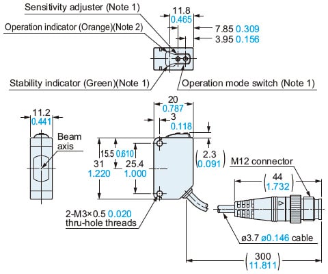
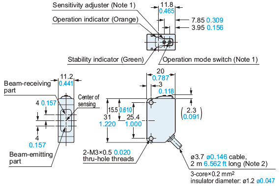
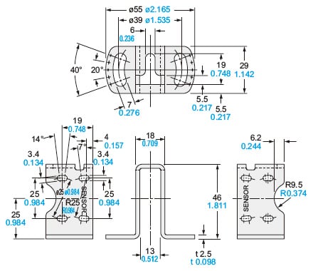
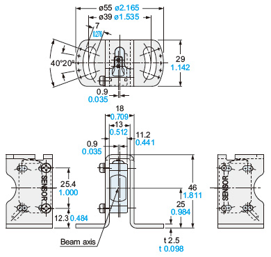
Dimensions
- Unit: mm in
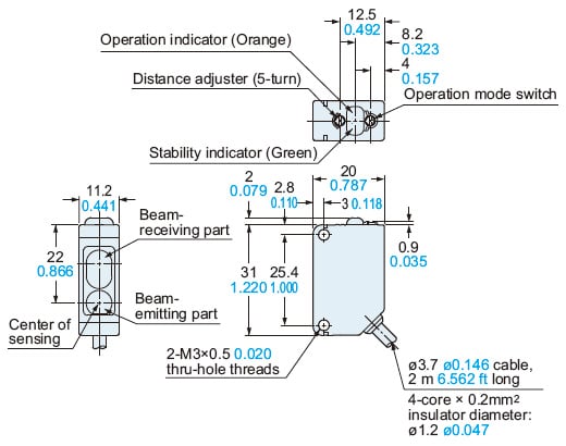
CX-41□
Sensor
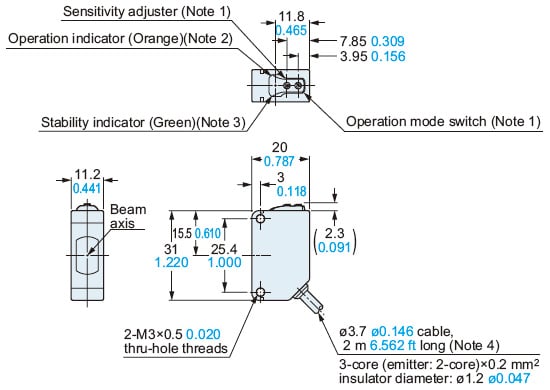
Notes:1) Not incorporated on the emitter and the basic type sensor.2) It is the power indicator (green) on the emitter.3) Not incorporated on the emitter.4) Basic type: 0.5 m1.640 ftlong
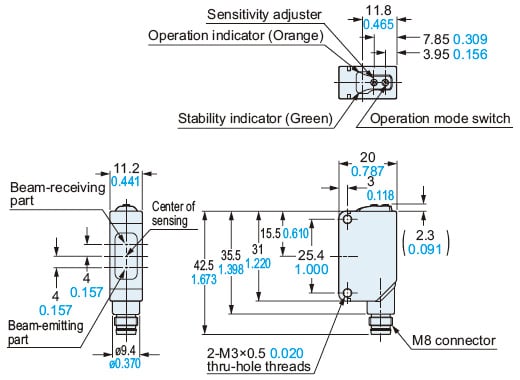
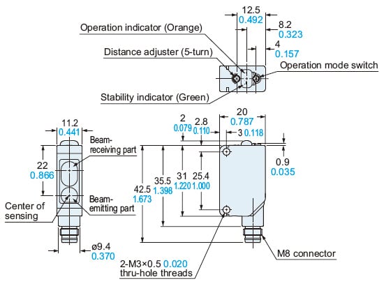
CX-41□-Z
Sensor
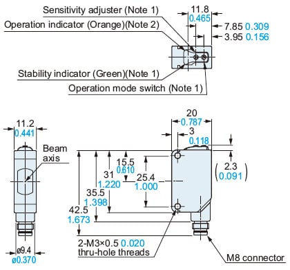
Notes:1) Not incorporated on the emitter.2) It is the power indicator (green) on the emitter.
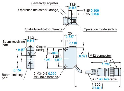
CX-41□-J
Sensor
Notes:1) Not incorporated on the emitter.2) It is the power indicator (green) on the emitter.
CX-49□
CX-48□
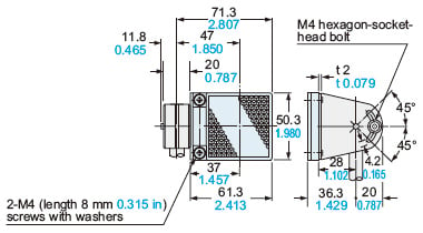
CX-42□
Sensor
CX-49□-Z
CX-48□-Z
CX-42□-Z
Sensor
CX-49□-J
CX-48□-J
CX-42□-J
Sensor
CX-44□
Sensor
CX-44□-Z
Sensor
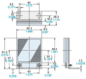
RF-230
Reflector
* Included in retroreflective type sensors except for sensors without reflector
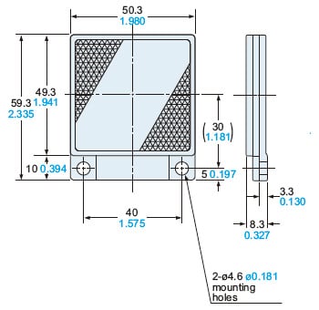
Material: Acrylic (Reflector), ABS (Base)
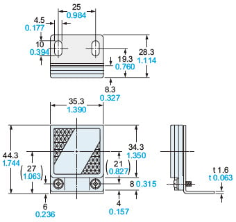
RF-220
Reflector (Optional)
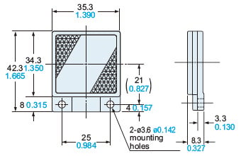
Material: Acrylic (Reflector), ABS (Base)
RF-210
Reflector (Optional)
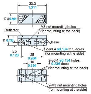
Material: Acrylic (Reflector), ABS (Base)Two M3 (length 8 mm0.315 in)screws with washers and two nuts are attached.
RF-11
Reflective tape (Optional)
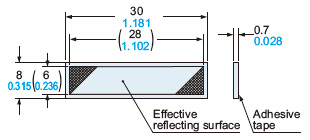
Material: Flexible Polyvinyl Chloride
RF-12
Reflective tape (Optional)
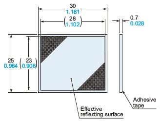
Material: Flexible polyvinyl chloride
RF-13
Reflective tape (Optional)
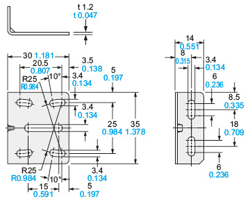
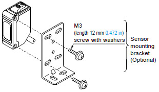
MS-CX2-1
Sensor mounting bracket (Optional)
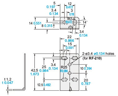
Material: Stainless steel (SUS304)Two M3 (length 12 mm0.472 in) screws with washers are attached.
Assembly dimensions
Mounting drawing with the receiver of CX-41□
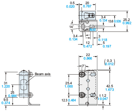
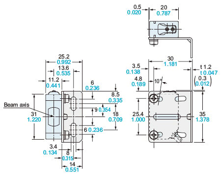
MS-CX2-2
Sensor mounting bracket (Optional)
Material: Stainless steel (SUS304)Two M3 (length 12 mm0.472 in) screws with washers are attached.
Assembly dimensions
Mounting drawing with the receiver of CX-41□
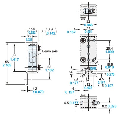
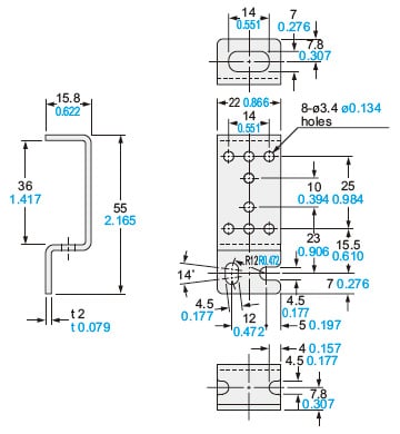
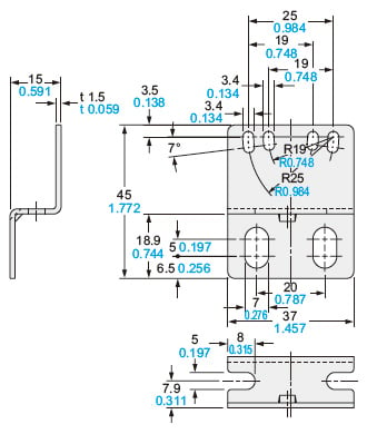
MS-CX2-4
Sensor mounting bracket (Optional)
Material: Stainless steel (SUS304)Two M3 (length 14 mm0.551 in) screws with washers are attached.
Assembly dimensions
Mounting drawing with the receiver of CX-41□
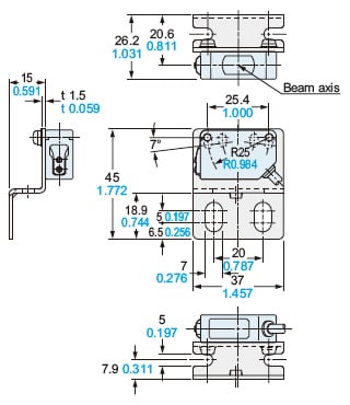
MS-CX2-5
Sensor mounting bracket (Optional)
Material: Stainless steel (SUS304)Two M3 (length 12 mm0.472 in) screws with washers are attached.
Assembly dimensions
Mounting drawing with the receiver of CX-41□
MS-CX-3
Sensor mounting bracket (Optional)
Material: Stainless steel (SUS304)Two M3 (length 12 mm0.472 in) screws with washers are attached.
Assembly dimensions
Mounting drawing with the receiver of CX-41□
MS-RF21-1
Reflector mounting bracket for RF-210 (Optional)
Material: Stainless steel (SUS304)Two M3 (length 12 mm0.472 in) screws with washers are attached.
Assembly dimensions
MS-RF22
Reflector mounting bracket for RF-220 (Optional)
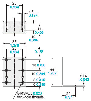
Material: Cold rolled carbon steel (SPCC) (Uni-chrome plated)Two M3 (length 8 mm0.315 in) screws with washers are attached.
Assembly dimensions
MS-RF23
Reflector mounting bracket for RF-230 (Optional)
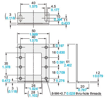
Material: Cold rolled carbon steel (SPCC), (Uni-chrome plated)Two M4 (length 10 mm0.394 in) screws with washers are attached.
Assembly dimensions
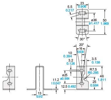
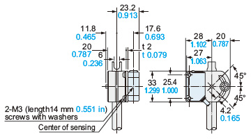
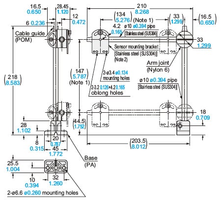
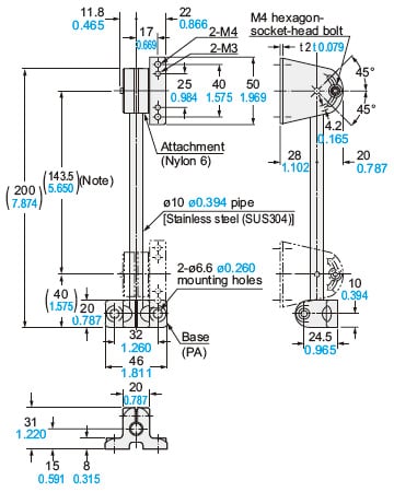
MS-AJ1
Basic assembly
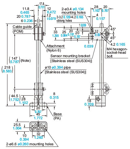
Two M3 (length 14 mm0.551 in) screws with washers, two M3 (length 16 mm0.630 in) screws with washers, two M3 (length 18 mm0.709 in) screws with washers, one auxiliary mounting plate for EQ-20 series and one auxiliary mounting plate for EX-40 series are attached.Note: The dimensions in the brackets indicate the adjustable range of the movable part.
Assembly dimensions with CX-400 series (Mounting part only)
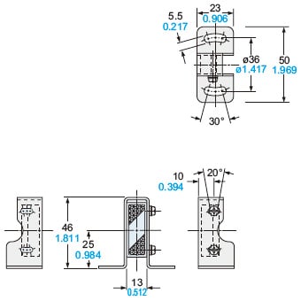
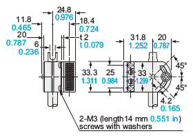
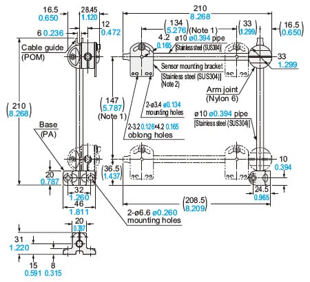
MS-AJ2
Basic assembly
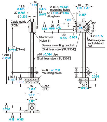
Two M3 (length 14 mm0.551 in) screws with washers, two M3 (length 16 mm0.630 in) screws with washers, two M3 (length 18 mm0.709 in) screws with washers, one auxiliary mounting plate for EQ-20 series and one auxiliary mounting plate for EX-40 series are attached.Note: The dimensions in the brackets indicate the adjustable range of the movable part.
Assembly dimensions with RF-210 (Reflector) (Mounting part only)
MS-AJ1-A
Lateral arm assembly
Two M3 (length 14 mm0.551 in) screws with washers, two M3 (length 16 mm0.630 in) screws with washers, two M3 (length 18 mm0.709 in) screws with washers, one auxiliary mounting plate for EQ-20 series and one auxiliary mounting plate for EX-40 series are attached.Notes:1) The dimensions in the brackets indicate the adjustable range of the movable part.2) Refer to MS-AJ1 / MS-AJ2 for the assembly dimensions with the sensor mounting bracket, sensor or reflector.
MS-AJ2-A
Lateral arm assembly
Two M3 (length 14 mm0.551 in) screws with washers, two M3 (length 16 mm0.630 in) screws with washers, two M3 (length 18 mm0.709 in) screws with washers, one auxiliary mounting plate for EQ-20 series and one auxiliary mounting plate for EX-40 series are attached.Notes:1) The dimensions in the brackets indicate the adjustable range of the movable part.2) Refer to MS-AJ1 / MS-AJ2 for the assembly dimensions with the sensor mounting bracket, sensor or reflector.
MS-AJ1-M
Assembly for reflector
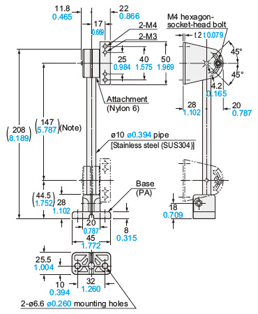
Note: The dimensions in the brackets indicate the adjustable range of the movable part.
Assembly dimensions with RF-220 (Reflector) (Mounting part only)
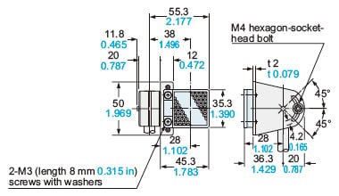
MS-AJ2-M
Assembly for reflector
Two M3 (length 8 mm0.315 in) screws with washers and two M4 (length 8 mm0.315 in) screws with washers are attached.Note: The dimensions in the brackets indicate the adjustable range of the movable part.
Assembly dimensions with RF-230 (Reflector) (Mounting part only)
------------------------------ Tab7 showing ------------------------------
I/O Circuit and Wiring diagrams
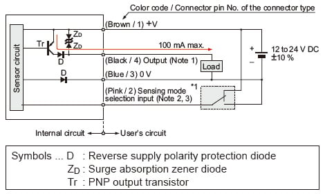
NPN output type
I/O circuit diagram
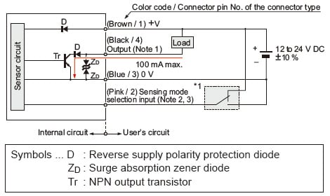
Notes:
1)The emitter of the thru-beam type sensor does not incorporate the output.
2)Sensing mode selection input is incorporated only for the CX-44□ adjustable range reflective type. When using the CX-44□, be sure to wire the sensing mode selection input (pink / 2) as mentioned*1. Unstable operation may occur.
3)When the mating cable is connected to the plug-in connector type of CX-44□, its color is white.
*1:
Sensing mode selection input
BGS function: Connect to 0 V
FGS function: Connect to +V
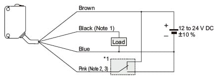
Wiring diagram
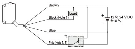
Notes:
1)The emitter of the thru-beam type sensor does not incorporate the black wire.
2)The pink wire is incorporated only for the CX-44□ adjustable range reflective type. When using the CX-44□, be sure to wire the pink wire as mentioned*1. Unstable operation may occur.
3)When the mating cable is connected to the plug-in connector type of CX-44□, its color is white.
*1:
Sensing mode selection input
BGS function: Connect to 0 V
FGS function: Connect to +V
Connector pin position
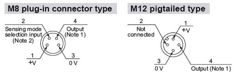
Notes:
1)The emitter of the thru-beam type sensor does not incorporate the output.
2)Sensing mode selection input is incorporated only for the CX-44□ adjustable range reflective type. When using the CX-44□, be sure to wire the sensing mode selection input (pink / 2). Unstable operation may occur.
PNP output type
I/O circuit diagram
Notes:
1)The emitter of the thru-beam type sensor does not incorporate the output.
2)Sensing mode selection input is incorporated only for the CX-44□-P adjustable range reflective type. When using the CX-44□-P, be sure to wire the sensing mode selection input (pink / 2) as mentioned*1. Unstable operation may occur.
3)When the mating cable is connected to the plug-in connector type of CX-44□-P, its color is white.
*1:
Sensing mode selection input
BGS function: Connect to 0 V
FGS function: Connect to +V
Wiring diagram
Notes:
1)The emitter of the thru-beam type sensor does not incorporate the black wire.
2)The pink wire is incorporated only for the CX-44□-P adjustable range reflective type. When using the CX-44□-P, be sure to wire the pink wire as mentioned*1. Unstable operation may occur.
3)When the mating cable is connected to the plug-in connector type of CX-44□-P, its color is white.
*1:
Sensing mode selection input
BGS function: Connect to 0 V
FGS function: Connect to +V
Connector pin position
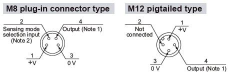
Notes:
1)The emitter of the thru-beam type sensor does not incorporate the output.
2)Sensing mode selection input is incorporated only for the CX-44□-P adjustable range reflective type. When using the CX-44□-P, be sure to wire the sensing mode selection input (pink / 2). Unstable operation may occur.
------------------------------ Tab8 showing ------------------------------
Sensing characteristics
*TYPICAL
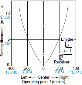
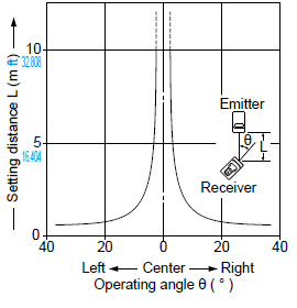
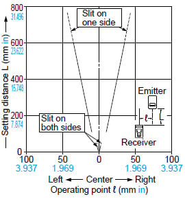
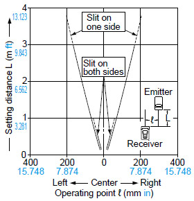
CX-411□
Thru-beam type
Parallel deviation
Angular deviation
Parallel deviation with round slit masks
(ø0.5 mm ø0.020 in)
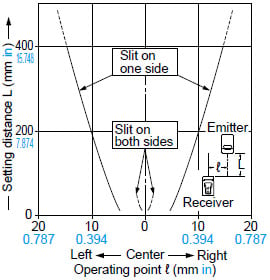
Parallel deviation with round slit masks
(ø1 mm ø0.039 in)
Parallel deviation with round slit masks
(ø2 mm ø0.079 in)
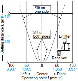
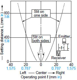
Parallel deviation with rectangular slit masks
(0.5 × 6 mm 0.020 × 0.236 in)
Parallel deviation with rectangular slit masks
(1 × 6 mm 0.039 × 0.236 in)
Parallel deviation with rectangular slit masks
(2 × 6 mm 0.079 × 0.236 in)
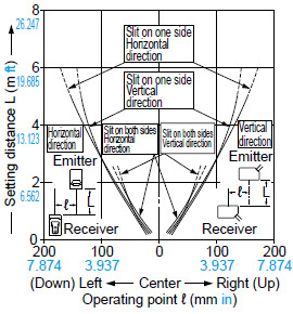
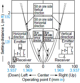
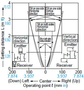
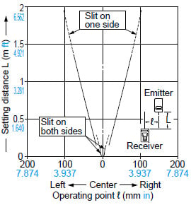
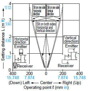
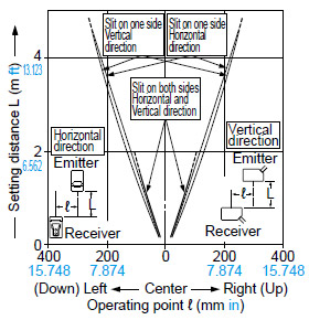
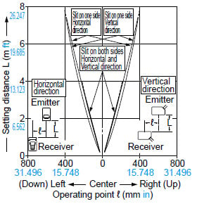
CX-412□
Thru-beam type
Parallel deviation
Angular deviation
Parallel deviation with round slit masks
(ø0.5 mm ø0.020 in)
Parallel deviation with round slit masks
(ø1 mm ø0.039 in)
Parallel deviation with round slit masks
(ø2 mm ø0.079 in)
Parallel deviation with rectangular slit masks
(0.5 × 6 mm 0.020 × 0.236 in)
Parallel deviation with rectangular slit masks
(1 × 6 mm 0.039 × 0.236 in)
Parallel deviation with rectangular slit masks
(2 × 6 mm 0.079 × 0.236 in)
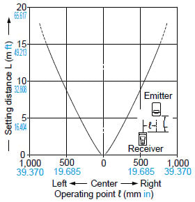
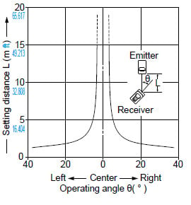
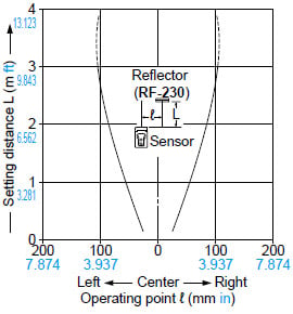
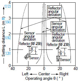
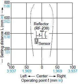
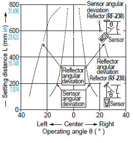
CX-491□
Retroreflective type
Parallel deviation
Angular deviation
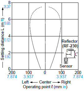
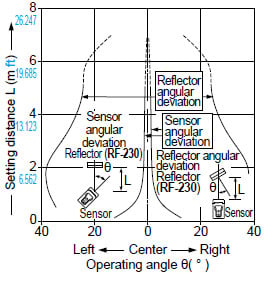
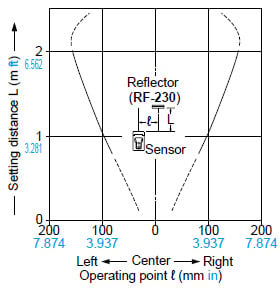
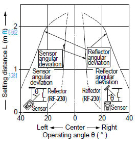
CX-493□
Retroreflective type
Parallel deviation
Angular deviation
CX-481□
Retroreflective type
Parallel deviation
Angular deviation
CX-482□
Retroreflective type
Parallel deviation
Angular deviation
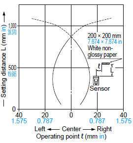
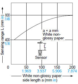
CX-424□
Diffuse reflective type
Sensing field
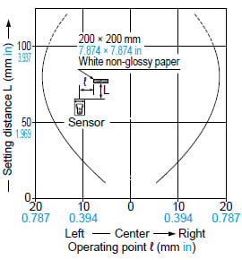
Correlation between sensing object size and sensing range
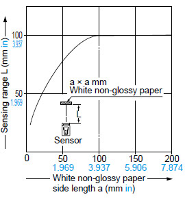
As the sensing object size becomes smaller than the standard size (white non-glossy paper 200 × 200 mm 7.874 × 7.874 in), the sensing range shortens, as shown in the left graph.
(For plotting the left graph, the sensitivity has been set such that a 200 × 200 mm 7.874 × 7.874 in white non-glossy paper is just detectable at a distance of 100 mm 3.937 in.)
CX-421□
Diffuse reflective type
Sensing field
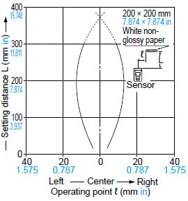
Correlation between sensing object size and sensing range
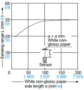
As the sensing object size becomes smaller than the standard size (white non-glossy paper 200 × 200 mm 7.874 × 7.874 in), the sensing range shortens, as shown in the left graph.
(For plotting the left graph, the sensitivity has been set such that a 200 × 200 mm 7.874 × 7.874 in white non-glossy paper is just detectable at a distance of 300 mm 11.811 in.)
CX-422□
Diffuse reflective type
Sensing field
Correlation between sensing object size and sensing range
As the sensing object size becomes smaller than the standard size (white non-glossy paper 200 × 200 mm 7.874 × 7.874 in), the sensing range shortens, as shown in the left graph.
(For plotting the left graph, the sensitivity has been set such that a 200 × 200 mm 7.874 × 7.874 in white non-glossy paper is just detectable at a distance of 800 mm 31.496 in.)
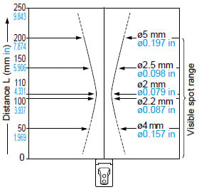
CX-423□
Diffuse reflective type
Sensing field
Correlation between sensing object size and sensing range
As the sensing object size becomes smaller than the standard size (white non-glossy paper 200 × 200 mm 7.874 × 7.874 in), the sensing range shortens, as shown in the left graph.
(For plotting the left graph, the sensitivity has been set such that a 200 × 200 mm 7.874 × 7.874 in white non-glossy paper is just detectable at a distance of 200 mm 7.874 in. Contact us for the sensing characteristics of 300 mm 11.811 in distance. Please contact us for the sensing field at the setting distance 300 mm 11.811 in.)
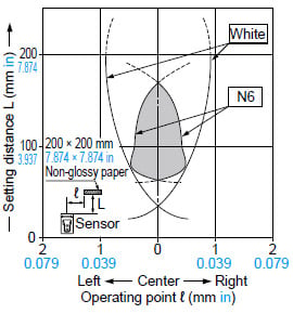
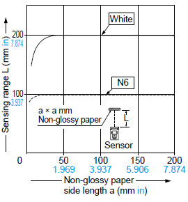
Correlation between lightness and sensing range
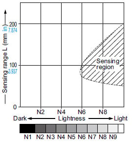
The sensing region is represented by oblique lines in the left figure.
However, the sensitivity should be set with an enough margin because of slight variation in products.
(Lightness shown on the left may differ slightly from the actual object condition.)
Emitted beam
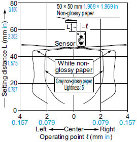
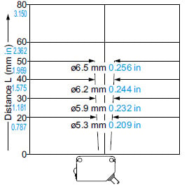
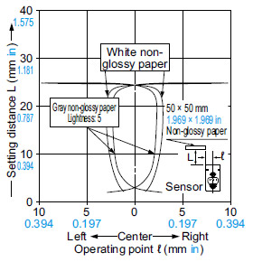
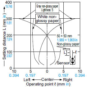
CX-441□
Adjustable range reflective type
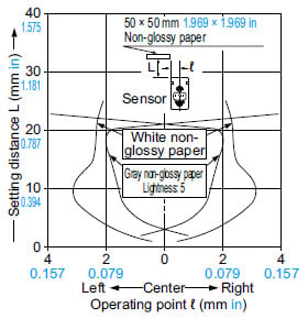
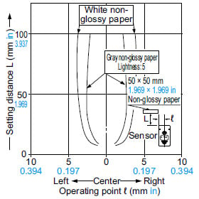
Sensing fields
・Setting distance: 25 mm 0.984 in
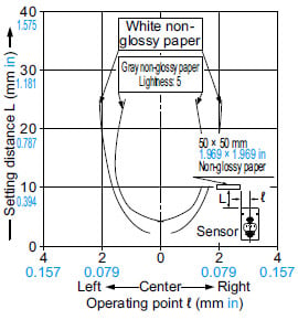
・Setting distance: 50 mm 1.969 in
Emitted beam
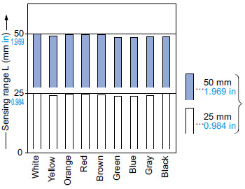
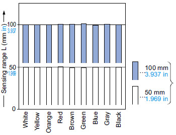
Correlation between color
(50 × 50 mm 1.969 × 1.969 in construction paper) and sensing range
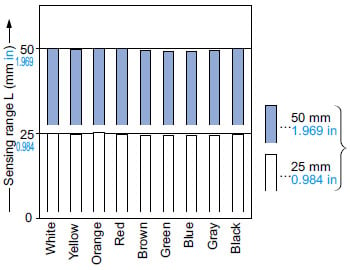
These bars indicate the sensing range with the respective colors when the distance adjuster is set to a sensing range of 50 mm 1.969 in and 25 mm 0.984 in long, respectively, with white color.
The sensing range also varies depending on material.
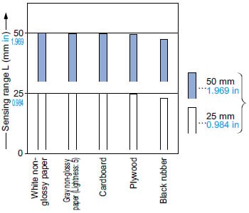
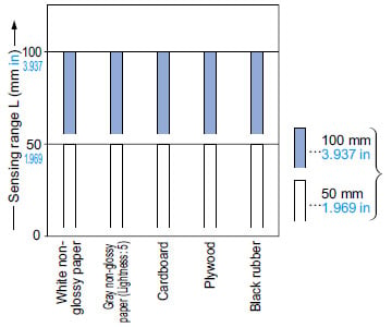
Correlation between material
(50 × 50 mm 1.969 × 1.969 in) and sensing range
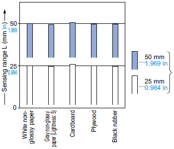
These bars indicate the sensing range with the respective objects when the distance adjuster is set to a sensing range of 50 mm 1.969 in and 25 mm 0.984 in long, respectively, with white non-glossy paper.
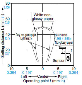
CX-443□ (Discontinued products)
Adjustable range reflective type
Sensing fields
・Setting distance: 25 mm 0.984 in
・Setting distance: 50 mm 1.969 in
Emitted beam
Correlation between color
(50 × 50 mm 1.969 × 1.969 in construction paper) and sensing range
These bars indicate the sensing range with the respective colors when the distance adjuster is set to a sensing range of 50 mm 1.969 in and 25 mm 0.984 in long, respectively, with white color.
The sensing range also varies depending on material.
Correlation between material
(50 × 50 mm 1.969 × 1.969 in) and sensing range
These bars indicate the sensing range with the respective objects when the distance adjuster is set to a sensing range of 50 mm 1.969 in and 25 mm 0.984 in long, respectively, with white non-glossy paper.
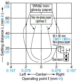
CX-444□
Adjustable range reflective type
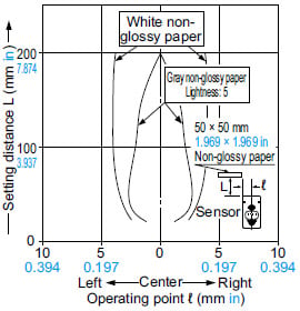
Sensing fields
・Setting distance: 25 mm 0.984 in
・Setting distance: 50 mm 1.969 in
・Setting distance: 100 mm 3.937 in
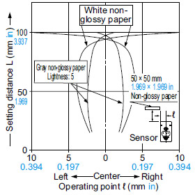
Emitted beam
Correlation between color
(50 × 50 mm 1.969 × 1.969 in construction paper) and sensing range
These bars indicate the sensing range with the respective colors when the distance adjuster is set to a sensing range of 100 mm 3.937 in and 50 mm 1.969 in long, respectively, with white color.
The sensing range also varies depending on material.
Correlation between material
(50 × 50 mm 1.969 × 1.969 in) and sensing range
These bars indicate the sensing range with the respective objects when the distance adjuster is set to a sensing range of 100 mm 3.937 in and 50 mm 1.969 in long, respectively, with white non-glossy paper.
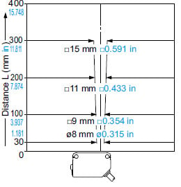
CX-442□
Adjustable range reflective type
Sensing fields
・Setting distance: 100 mm 3.937 in
・Setting distance: 200 mm 7.874 in
・Setting distance: 300 mm 11.811 in
Emitted beam
Correlation between color
(50 × 50 mm 1.969 × 1.969 in construction paper) and sensing range
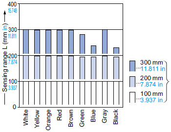
These bars indicate the sensing range with the respective colors when the distance adjuster is set to a sensing range of 300 mm 11.811 in, 200 mm 7.874 in and 100 mm 3.937 in long, respectively, with white color.
The sensing range also varies depending on material.
Correlation between material
(50 × 50 mm 1.969 × 1.969 in) and sensing range
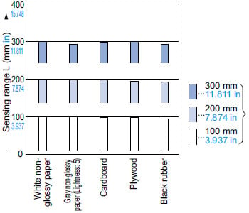
These bars indicate the sensing range with the respective objects when the distance adjuster is set to a sensing range of 300 mm 11.811 in, 200 mm 7.874 in and 100 mm 3.937 in long, respectively, with white non-glossy paper.
------------------------------ Tab9 showing ------------------------------
Mounting
- The tightening torque should be 0.5 N·m or less.
Wiring
- Make sure that the power supply is off while wiring.
- Take care that wrong wiring will damage the sensor.
- Verify that the supply voltage variation is within the rating.
- If power is supplied from a commercial switching regulator, ensure that the frame ground (F.G.) terminal of the power supply is connected to an actual ground.
- In case noise generating equipment (switching regulator, inverter motor, etc.) is used in the vicinity of this product, connect the frame ground (F.G.) terminal of the equipment to an actual ground.
- Do not run the wires together with high-voltage lines or power lines or put them in the same raceway.
This can cause malfunction due to induction. - When connecting an inductive load such as a relay to the output, do not connect a capacitive load to prevent resonance. Also, connect a diode to protect the output circuit.
- Extension up to total 100 m 328.084 ft (thru-beam type: both emitter and receiver) is possible with 0.3 mm2, or more, cable. However, in order to reduce noise, make the wiring as short as possible.
- Make sure that stress by forcible bend or pulling is not applied directly to the sensor cable joint.
Others
- This product has been developed / produced for industrial use only.
- Do not use during the initial transient time (50 ms) after the power supply is switched on.
- Take care that the sensor is not directly exposed to fluorescent light from a rapid-starter lamp or a high frequency lighting device, as it may affect the sensing performance.
- This sensor is suitable for indoor use only.
- Do not use this sensor in places having excessive vapor, dust, etc., or where it may come in direct contact with water or corrosive gas.
- Take care that the sensor does not come in direct contact with water, oil, grease or organic solvents, such as, thinner, etc.
- This sensor cannot be used in an environment containing inflammable or explosive gases.
- Never disassemble or modify the sensor.