Basic Information
Now it is possible to directly connect digital sensors to CC-Link Contributes to wire-saving, construction-saving, traceability, preventive maintenance, and more


Features
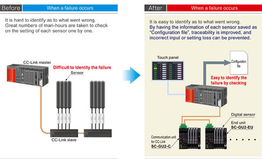
Traceability
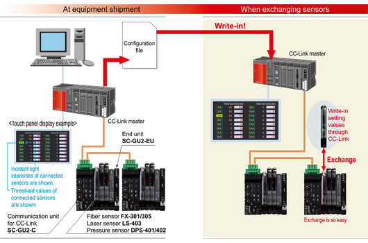
By keeping track of the sensor configurations at equipment start-up, any failure that may occur after equipment delivery can be eliminated in early stages.
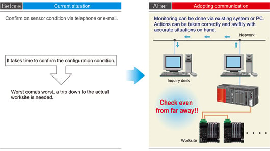
Remote monitoring of equipment
It is possible to check the sensor configurations through open network when a failure occurs in the equipment or production line, so that the on-site man-hours taken can be kept to the minimum.
Highly efficient maintenance
By having the configurations saved as "Configuration file" before equipment shipment, later on when it comes to exchanging the sensors, the configurations can be simply written in to CC-Link. Also, exchanges can be done easily with connection connectors without any extra tools.
Preventive maintenance
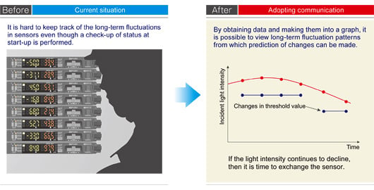
Take in digital data such as incident light intensity or pressure value of sensors and graph them out for preventive maintenance.
(e.g.) Light attenuated due to dirt on fiber sensor.
Reduction of wiring, construction and space
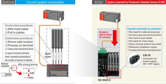
Space for installing a CC-Link slave is eliminated. Cascade connection is simply done by connectors so that the time taken for wiring and construction can be cut down.
Order guide
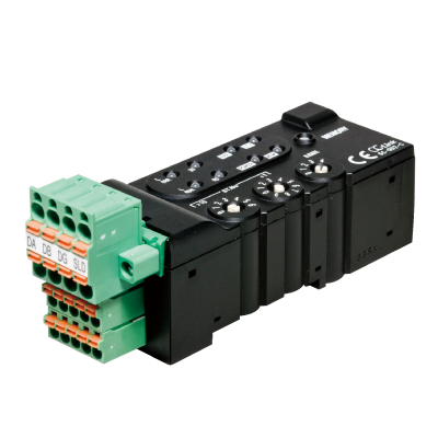
Communication units
| Designation | Appearance | Model No. | Description |
|---|---|---|---|
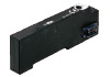
| Communication unit for CC-Link |
| SC-GU2-C | This is a communication unit, which can convert the output signal of a sensor amplifier into communication data for CC-Link. |
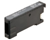
| End unit |
| SC-GU2-EU | This end unit can change and check the settings of sensor amplifiers that allow optical communication and monitor operation status. |
Connector input extension unit
| Designation | Appearance | Model No. | Description | |
|---|---|---|---|---|
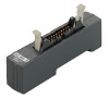
| 1-channel connector input extension unit |
| SC-T1J | Allows the connection of input device, such as sensor or switch. Incorporates a power indicator and an input signal indicator (1 ch). | |
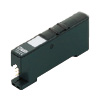
| Analog communication unit |
| SC-T1JA | This product can be connected with input devices such as sensors and switches. Also, the product can monitor by using 1 to 5 V analog voltage output, which is outputted by the input devices. *When communicating the converted value from analog to digital, the end unit SC-GU2-EU should be used. | |
Plug-in sensor units (MIL connectors)
| Designation | Appearance | Model No. | Description |
|---|---|---|---|
| Plug-in sensor separate unit |
| SC-MIL-S | Distributed installation by the MIL connector is possible by combining the plug-in sensor separate unit SC-MIL-S and the plug-in sensor main unit SC-MIL. |
| Plug-in sensor main unit |
| SC-MIL |
Optical communication compatible amplifier
| Type | Appearance | Model No. | Combined head | Description | ||
|---|---|---|---|---|---|---|
| Digital fiber sensor | FX-500 series | Standard type |  | FX-501 | FT-□ FD-□ FR-□ | NPN open-collector transistor |
| Two outputs type | FX-502 | NPN open-collector transistor two outputs (Note) | ||||
| Digital laser sensor |  | LS-403 | LS-H□ | NPN open-collector transistor | ||
| Digital pressure sensor | For combined pressure / negative pressure |  | DPS-401 | DPH-101□ DPH-103□ | NPN open-collector For transistor two outputs (Note) | |
| For positive pressure | DPS-402 | DPH-102□ | ||||
Note: To receive the output signal from the Output 2, it is required to perform optical communication by simultaneously using the end unit SC-GU2-EU.
Others
| Designation | Appearance | Model No. | Description |
|---|---|---|---|
| Non-line connector |
| CN-70 | This one-touch connector is used to connect the following devices to SC-GU2-C: The FX-500/300/311/400 fiber sensor, the LS-401/403 laser sensor, digital pressure sensor DPS-401/402, the GA-311 compact inductive proximity sensor, etc. |
| End plate (Note) |
| MS-DIN-E | After installing SC-GU2-C, sensor amplifier, SC-GU2-EU etc. in cascade on a DIN rail, these end plates clamp the units into place on both sides. Be sure to use this product. [Two pcs. per set] |


Note:Commercially available DIN rail stopper can also be used.
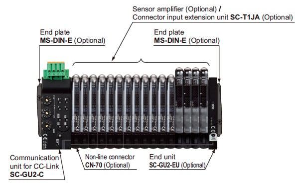
System Composition
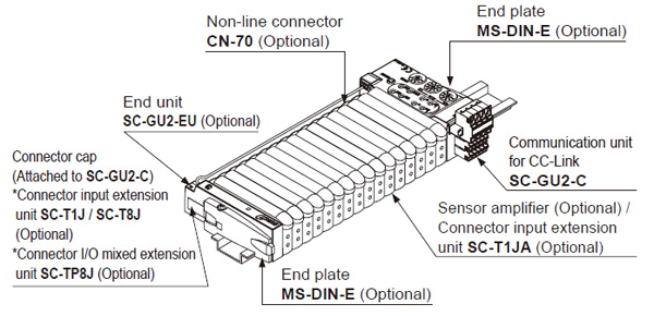
* The SC-T1J is positioned on the outside of the end unit.Transmits ON / OFF signal only.Does not respond to data communication.
Options
| Designation | Appearance | Model No. | Description | |
|---|---|---|---|---|
| 4-pin type snap male connector |  | SL-CP1 (White) | For 0.08 to 0.2 mm2 (Conductor cross-section area) Wire dia.: ø0.7 to ø1.2 mm ø0.028 to ø0.047 in (10 pcs. per set) | Snap male connectors are utilized to connect input devices to both the 1-channel connector input extension unit SC-T1J. SC-T1J includes one SL-CP1. |
 | SL-CP2 (Black) | For 0.3 mm2 (Conductor cross-section area) Wire dia.: ø1.1 to ø1.6 mm ø0.043 to ø 0.063 in (10 pcs. per set) | ||
 | SL-CP3 (Greenish blue) | For 0.5 mm2 (Conductor cross-section area) Wire dia.: ø1.7 to ø2.5 mm ø0.067 to ø0.098 in (10 pcs. per set) | ||
| Male / female connector exclusive pliers |  | SL-JPC | Snap female connector and snap male connector (SL-CP1, CP2) can be connected in one grip. | |
| SL-CP3 exclusive pliers |  | SL-JPE | 4-pin type snap male connector (SL-CP3) can be connected in one grip. | |
| Designation | Model No. | Description | |
|---|---|---|---|
| Input connector | CN-EP1 | For 1 ch connector input unit (analog communication unit) SC-T1JA (5 pcs. per set) | Input connector is utilized to connect input devices to the 1-channel connector input unit (analog communication unit) SC-T1JA. SC-T1JA includes one CN-EP1. |
Input connector
- CN-EP1

Specifications
Communication unit for CC-Link
| Designation | Communication unit for CC-Link | ||||
|---|---|---|---|---|---|
| Model No. | SC-GU2-C | ||||
| Applicable sensor amplifier (Note 2) | Sensor amplifiers (NPN output type) that can connect to non-line connector CN-70 (optional) (FX-500/300/311/410 series, LS-401/403, DPS-401/402, GA-311) | ||||
| Number of connectable units | Max. 16 units (Sensor amplifiers / input units) per SC-GU2-C (Maximum of 12 units including the FX-500 Series can communicate optically) | ||||
| Supply voltage | 24 V DC +10−15 % Ripple P-P 10 % or less | ||||
| Current consumption | 110 mA or less (excluding connected sensor amplifiers / input units) | ||||
| Allowable passing current | Wire-saving connector 2 A (Note 3), supply connector 6 A (Note 4) | ||||
| Communication method | CC-Link Ver.1.10 | ||||
| Number of occupied station | Switchable 1 or 4 station | ||||
| Baud rate | 10 Mbps | 5 Mbps | 2.5 Mbps | 625 kbps | 156 kbps |
| Total extension length | 100 m 328.084 ft | 150 m 492.126 ft | 200 m 656.168 ft | 600 m 1968.504 ft | 1,200 m 3937.008 ft |
| Communication cable | Specified cable (twist pair cable with shield) (Note 5) | ||||
| Station No. setting | 1 to 64 (0 and 65 or more: Error) | ||||
| Remote station type | Remote device station | ||||
| Ambient temperature | –10 to +55 ℃ +14 to +131 ℉ (If 4 to 7 units are connected in cascade: –10 to +50 ℃ +14 to +122 ℉, if 8 to 16 units are connected in cascade : –10 to +45 ℃ +14 to +113 ℉) (No dew condensation or icing allowed), Storage: –20 to +70 ℃ –4 to +158 ℉ | ||||
| Ambient humidity | 35 to 85 % RH, Storage: 35 to 85 % RH | ||||
| Material | Enclosure: Heat-resistant ABS, Connector cap: Silicone rubber | ||||
| Weight | Net weight: 60 g approx., Gross weight: 100 g approx. | ||||
| Accessory | Connector cap: 2 pcs. | ||||
Notes:
1) Where measurement conditions have not been specified precisely, the conditions used were an ambient temperature of +23 ℃ +73.4℉.
2) Only the below models respond to data communication.
FX-501/502, LS-403, DPS-401/402
3) Be sure to check that total current consumption of sensor amplifiers connected in cascade does not exceed allowable passing current.
4) In case of supplying power to other devices, be sure to set the current less than allowable passing current.
5) Use the CC-Link-specified cable.
1-channel connector input extension unit
| Designation | 1-channel connector input extension unit |
|---|---|
| Analog communication unit | |
| Model No. | SC-T1JA |
| Supply voltage | 12 to 24 V DC ±10 % Ripple P-P 10 % or less (By power supplied from the SC-GU2-C.) |
| Current consumption (Note 2) | Max. 25 mA or less (when all indicators light up) |
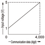
| Analog voltage input | Input voltage range: 1 to 5 V DC Input impedance: 200 kΩ approx. |
| Communication data (Note 3) | Analog <--> Communication data • Communication data: 0 to 4,000 digits (in the range of 1 to 5 V) • Zero point: Within 0 digit ±0.5 % F.S. • Span: Within 4,000 digits ±0.5 % F.S. • Linearity: Within ±0.5 % F.S. |
| Input | Connectable device: Output type of NPN open-collector transistor Supply current for input device: 100 mA or less Input impedance: 17 kΩ approx. Operating voltage: 17 V or more at ON voltage (between input and +V at 24 V) 4 V or less at OFF voltage (between input and +V at 24 V) |
| Output | NPN open-collector transistor • Max. sink current: 50 mA • Applied voltage: 30 V DC or less • Residual voltage: 1.5 V or less (at 50 mA sink current) |
| Power indicator | Green LED (lights up when the power is ON) |
| Input indicator | Green LED (lights up when NPN input is ON) |
| Ambient temperature | –10 to +55 ℃ +14 to +131 ℉ (If 4 to 7 units are connected in cascade: –10 to +50 ℃ +14 to +122 ℉, if 8 to 16 units are connected in cascade : –10 to +45 ℃ +14 to +113℉) (No dew condensation or icing allowed), Storage: –10 to +70 ℃ +14 to +158 ℉ |
| Ambient humidity | 35 to 85 % RH, Storage: 35 to 85 % |
| Temperature characteristics | Within ±1 % F.S. (at +25 ℃ +77 ℉ reference) |
| Material | Enclosure: Heat-resistant ABS |
| Weight | Net weight: 20 g approx., Gross weight: 40 g approx. |
| Accessory | Connector (e-CON): 1 pc. |
Notes:
1) Where measurement conditions have not been specified precisely, the conditions used were an ambient temperature of +23 ℃ +73.4 ℉.
2) The current consumption and input current of output device connected are not included.
3) The relationship between communication data and input voltage is as described in the below figure.
End unit
| Designation | End unit | |
|---|---|---|
| Model No. | SC-GU2-EU | |
| Supply voltage | 12 to 24 V DC +10−15 % Ripple P-P 10 % or less (By power supplied from the SC-GU2-C) | |
| Current consumption | 10 mA or less | |
| Signal channel No. | - (Not occupy the signal channel No.) | |
| Power indicator | Green LED (lights up when the power is ON) | |
| Cable | Type | 0.38 mm2 single shielded cable [Heat resistant PVC (Black)] |
| Sheath outer diameter | φ1.46 mm φ0.057 in | |
| Length | 30 to 180 mm 1.181 to 7.087 in adjustable by cable length adjust button | |
| Tensile strength | Main body side: 20 N (Note 2) | |
| Material | Enclosure: Heat-resistant ABS | |
| Weight | Net weight: 20 g approx., Gross weight: 40 g approx. | |
Notes:
1) Where measurement conditions have not been specified precisely, the conditions used were an ambient temperature of +23 ℃ +73.4 ℉.
2) For length adjustment of cable with communication connector, pull out the cable slowly. To remove the cable with communication connector from SC-GU2-C, hold the connector and remove it.
Connector input extension units
| Designation | 1-channel connector input extension unit | |
|---|---|---|
| Model No. | SC-T1J | |
| Supply voltage | 12 to 24 V DC ±10 % (By power supplied from the SC-GU2-C) | |
| Current consumption (Note 2) | 20 mA or less (when all indicators light up) | |
| Signal channel No. | 1 input | |
| Connectable device | NPN open-collector, or DC 2-wire output type sensor, or switch etc. | |
| Supply current for units (Note 3) | 100 mA or less | |
| Power indicator | Green LED (Lights up when the power is ON) | |
| Input indicator | Green LED (Lights up when each channel input is ON) | - |
| Ambient temperature | –10 to +45 ℃ +14 to +113 ℉ (No dew condensation or icing allowed), Storage: –20 to +70 ℃ –4 to +158 ℉ | |
| Ambient humidity | 35 to 85 % RH, Storage: 35 to 85 % RH | |
| Material | Enclosure: Heat-resistant ABS | |
| Net weight | 10 g approx. | |
| Accessories | SL-CP1 (Snap male connector): 1 pc. |
Notes:
1) Where measurement conditions have not been specified precisely, the conditions used were an ambient temperature of +20 ℃ +68 ℉.
2) The current consumption and input current of the input unit connected are not included.
3) Set the maximum current passing through input / output line to 50 mA or less.
Plug-in Sensor units (MIL connectors)
| Designation | Separate unit | Main unit |
|---|---|---|
| Model No. | SC-MIL-S | SC-MIL |
| Supply voltage | By power supplied from the SC-GU2-C | 12 to 24 V DC ±10 % (Note 2) By power supplied from the SC-GU2-C |
| Allowable through current (Note 3) | 1 A or less (Same as maximum permissible current consumption of all units connected to SC-MIL-S.) | 2 A or less (Same as maximum permissible current consumption of all units connected to SC-MIL.) |
| Signal channel No. | Connectable up to 16 channels (The signal from up to 16th point (counting from unit adjacent to SC-MIL) of all units connected to SC-MIL is transferred. However, the signal thereafter is not transferred. Note that SC-MIL and SC-MIL-S do not occupy any signal point.) | |
| Max. distance between units | 10 m 32.808 ft or less (the distance between SC-MIL and PLC and that between SC-MIL and SC-MIL-S put together) | |
| Ambient temperature | –10 to +45 ℃ +14 to +113 ℉ (No dew condensation or icing allowed), Storage: –20 to +70 ℃ –4 to +158 ℉ | |
| Ambient humidity | 35 to 85 % RH, Storage: 35 to 85 % RH | |
| Material | Enclosure: Heat-resistant ABS | |
| Weight | Net weight: 20 g approx. | Net weight: 25 g approx. |
| Accessory | Connector protection seal: 1 pc. | |
Notes:
1) Where measurement conditions have not been specified precisely, the conditions used were an ambient temperature of +20 ℃ +68 ℉.
2) The plug-in sensor main unit SC-MIL incorporates a cable lead-out connector in addition to the MIL connector, which allows to receive the supply voltage from the separate power supply.
3) When either the power supply device’s allowable amount of current or the connecting cable’s allowable amount of current is smaller than the allowable current passage value, match it with the smallest specification.
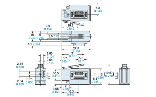
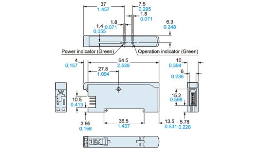
Dimensions
- Unit: mm in
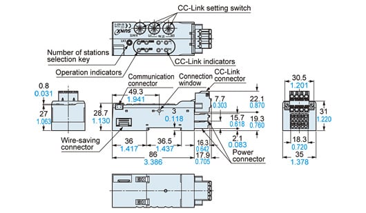
SC-GU2-C
Communication unit for CC-Link
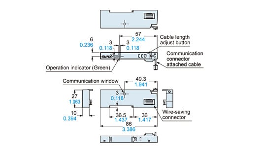
SC-GU2-EU
End unit
SC-T1JA
1-channel connector input extension unit
CN-70
Non-line connector