Basic Information
Taking fiber sensors to the next level


Features
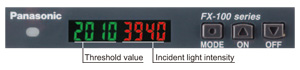
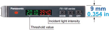
Good dual digital display
The threshold value and incident light intensity can be both confirmed at the same time, bringing good operability when making changes of each setting.
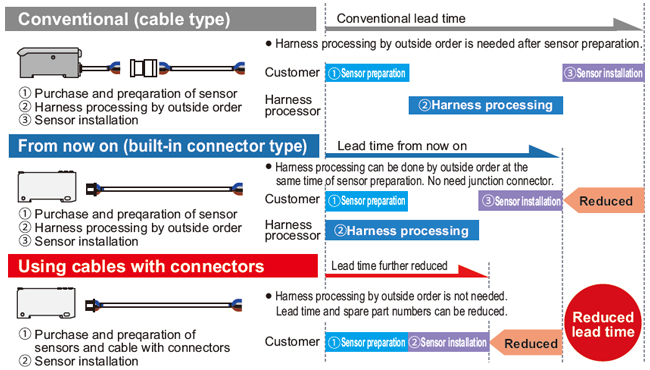
Commercially-available connectors reduce lead time and spare part numbers
Compatible with commercially-available connectors, so that processing costs and lead time required for processing after purchase can be greatly reduced. The connection parts same as the DP-100 series digital pressure sensors and the PM-65 series micro photoelectric sensors can be commonly used.
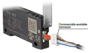
Commercially-available crimping connectors are used,
so that the processing costs for connection cables can be greatly reduced.
Saving-space with a width of 9 mm 0.354 in
Very slim body at only 9 mm 0.354 in. This is much thinner than existing fiber sensors. This makes a very large difference when using many units, even if the difference of one unit is small.
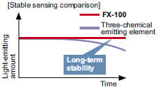
Improved stability over long terms
Utilizes "Four-chemical emitting element" for light emission. The light emission is guaranteed to be stable over long periods of time.
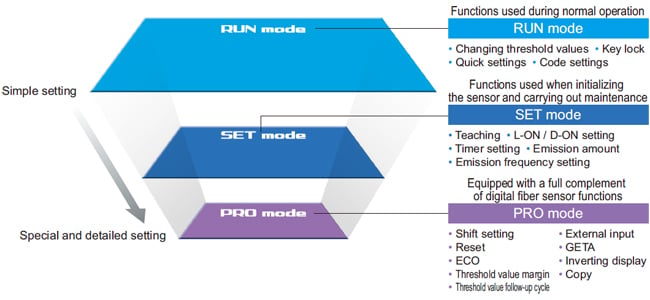
Simple operation due to clear configuration system
Continued to use the configuration system of digital pressure sensor DP-100 series, which has received high popularity since its release. We have separated the settings into three levels: RUN mode, SET mode, and PRO mode, making operation simpler and easier.
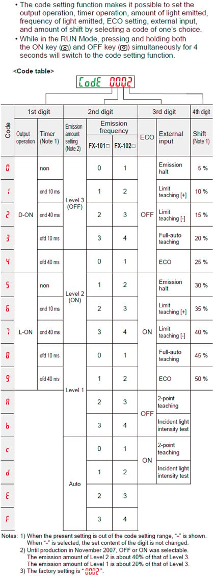
Quick code input function [RUN mode]
Simply imputing the default setting "code (number)" will enable sensor settings. Even if the settings are accidentally changed, imputing the code will restore the default settings.
Confirmation can be carried out smoothly via telephone by simply quoting numbers. This can be of great assistance when dealing with foreign country customers.
![Quick code input function [RUN mode]](https://tp.industry.panasonic.com/hubfs/pid-corp/products/fasys/sensor/fiber/fx-100/images/pic08.jpg)
Refer to "Quick setting function" and "Code setting function" in "PRECAUTIONS FOR PROPER USE" for details.
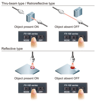
Teaching with ON / OFF keys
Simply press the ON key when an object is present, and OFF when it is not, and teaching is completed. There is no need to consider difference between Light-ON and Dark-ON.
(Setting example)
Teaching even without an object - Limit teaching function
Threshold value can be set by performing teaching only when an object is absent (when the incident light amount is stable). This is useful when there are other objects in the background also when defecting a minute objects. Teaching can also be carried out using external input.
Resolves variation in incident light intensity display GETA function [PRO mode]
Even when performing the same sensing operation, there may be variances in the digital values of the fiber amp. There is no problem with the sensor itself, but the operator may find it troubling.
Given value can be corrected with the GETA function, so the apparent variation can be eliminated and the creation of operation manuals can proceed smoothly.
![Resolves variation in incident light intensity display GETA function [PRO mode]](https://tp.industry.panasonic.com/hubfs/pid-corp/products/fasys/sensor/fiber/fx-100/images/pic10.jpg)
Threshold value follow-up cycle setting function [PRO mode]
This function seeks changes in the light emitting amount resulting from changes in the environment over long periods (such as dust levels), so that the incident light intensity can be checked at desired intervals and the threshold values can be reset automatically.
![Threshold value follow-up cycle setting function [PRO mode]](https://tp.industry.panasonic.com/hubfs/pid-corp/products/fasys/sensor/fiber/fx-100/images/pic11.jpg)
* Effective when the output operation is set to Dark-ON, and when using thru-beam type or retroreflective type fibers.
Emission amount setting function [SET mode]
Emission amount can be reduced in order to achieve stable detection when the receiving light level is saturated, such as detection at close range and detection of transparent or minute objects. Previously, the emission amount level was only one, but four level setting (three level + auto setting) has become available. This function brings easier settings than before.
![Emission amount setting function [SET mode]](https://tp.industry.panasonic.com/hubfs/pid-corp/products/fasys/sensor/fiber/fx-100/images/pic12.jpg)
Emission frequency setting mode [SET mode]
Mutual interference is prevented for max. 3 units for standard type FX-101□ and max. 4 units in case of long sensing range type FX-102□.
During setting of interference prevention, emitter and output indicator both flash, so it is convenient to confirm which fiber is in the setting process at a glance. Emitter flashes even when an amplifier is not installed close
together.
* When the emission frequency is changed, a response time is also changed.
![Emission frequency setting mode [SET mode]](https://tp.industry.panasonic.com/hubfs/pid-corp/products/fasys/sensor/fiber/fx-100/images/pic13.jpg)
The emitter and output indicator flash at the same frequency.
External input setting mode [PRO mode]
External input can be selected from emission halt, limit teaching / full-auto teaching / 2-level teaching, ECO or emission amount test. Threshold value set at each teaching is also memorized.
![External input setting mode [PRO mode]](https://tp.industry.panasonic.com/hubfs/pid-corp/products/fasys/sensor/fiber/fx-100/images/pic14.jpg)
Digital display inversion setting [PRO mode]
The viewing orientation of the digital display can be inverted in accordance with the setting direction of the amplifier.
![Digital display inversion setting [PRO mode]](https://tp.industry.panasonic.com/hubfs/pid-corp/products/fasys/sensor/fiber/fx-100/images/pic15.jpg)
Alert function [PRO mode]
When the amount light received approaches the threshold value, the display can be made to blink in order to alert the operator.
<When using at a shift amount of 20% and a threshold value of 1,000>
The amount of light received ranges from about 900 to 1,100 when the digital indicator flashes.
![Alert function [PRO mode]](https://tp.industry.panasonic.com/hubfs/pid-corp/products/fasys/sensor/fiber/fx-100/images/pic16.jpg)
Setting copy function to reduce man-hours and human error [PRO mode]
By connecting a fiber sensor to the master fiber sensor, the master sensor settings can be copied along with data communications. When the same settings are input to several units, trouble from setting errors can be prevented, also changes to the work order will be small when equipment design is changed.
<Wiring to copy settings>
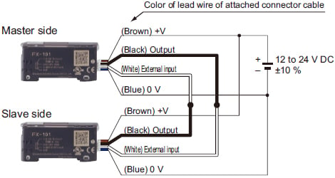
These settings can be copied
Threshold value, output operation, timer operation, timer emission amount, shift, external input, threshold valuestoring, ECO inverting digital display, and threshold value margin
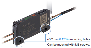
Without mounting bracket
Selectable either mounting on DIN rail or direct mounting with through hole.
Direct mounting brings stability even on a movable parts or installation of a single unit.
Available from standard type or long sensing range type
Standard type and long sensing range type are available which has various response time and sensing range.
The model best meet application needs can be selected.
| Model No. | Type | Sensing range (FT-43) | Response time |
|---|---|---|---|
| FX-101 | Standard type | 350 mm 13.780 in | Max. 250μ s |
| FX-102 | Long sensing range type | 970 mm 38.189 in | Max. 2.5 ms |
Power consumption saving with ECO mode

When there is no key operations in approximately 20 seconds, digital display turns off and power consumption can be reduced to 600mW or less (720mW in normal mode).
Order guide
Amplifiers
| Type | Appearance | Model No. | Emitting element | Output | |
|---|---|---|---|---|---|
| Standard type |
| FX-101 (Note 2) | Red LED | NPN open-collector transistor | |
| FX-101P (Note 2) | PNP open-collector transistor | ||||
| M8 plug-in connector type | FX-101-Z (Note 3) | NPN open-collector transistor | |||
| FX-101P-Z (Note 3) | PNP open-collector transistor | ||||
| Cable set (Note 1) | FX-101-CC2 | NPN open-collector transistor | |||
| FX-101P-CC2 | PNP open-collector transistor | ||||
| Long sensing range type | FX-102 (Note 2) | NPN open-collector transistor | |||
| FX-102P (Note 2) | PNP open-collector transistor | ||||
| M8 plug-in connector type | FX-102-Z (Note 3) | NPN open-collector transistor | |||
| FX-102P-Z (Note 3) | PNP open-collector transistor | ||||
| Cable set (Note 1) | FX-102-CC2 | NPN open-collector transistor | |||
| FX-102P-CC2 | PNP open-collector transistor | ||||
Note :
1)The connector attached cable 2 m 6.562 ft CN-14A-C2 is supplied with the amplifier.
2)Make sure to use the optional connector attached cable CN-14A(-R)-C□ or the connector CN-14A, or a connector manufactured by J.S.T. Mfg. Co., Ltd.
(contact: SPHD-001T-P0.5, housing: PAP-04V-S)
3)Make sure to use the optional M8 connector attached cable CN-24A-C□.
Accessory
CN-14A-C2
(Connector attached cable 2 m6.562 ft)* Only include cable set type
FC-FX-1
(Protection cover)
Option
| Designation | Model No. | Description | |
|---|---|---|---|
| Connector attached cable | CN-14A-C1 | 1 m 3.281 ft | 0.02 mm2 4-core cabtyre cable with connector on one end Cable outer diameter: ø3.7 mm ø0.146 in |
| CN-14A-C2 (Note 1) | 2 m 6.562 ft | ||
| CN-14A-C3 | 3 m 9.843 ft | ||
| CN-14A-C5 | 5 m 16.404 ft | ||
| Connector attached cable (Bending-resistant type) | CN-14A-R-C1 | 1 m 3.281 ft | |
| CN-14A-R-C2 | 2 m 6.562 ft | ||
| CN-14A-R-C3 | 3 m 9.843 ft | ||
| CN-14A-R-C5 | 5 m 16.404 ft | ||
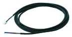
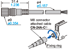
| M8 connector attached cable | CN-24A-C2 | 2 m 6.562 ft | For M8 plug-in connector type The connector on one end Cable outer diameter: ø4 mm ø0.157 in |
| CN-24A-C5 | 5 m 16.404 ft | ||
| Connector | CN-14A | Set of 10 housings and 40 contacts | |
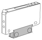
| Amplifier mounting bracket | MS-DIN-4 | Mounting bracket for amplifier | |
| End plates | MS-DIN-E 2 pcs. per set | When an amplifier moves depending on the way it is installed on a DIN rail, these end plates clamp amplifiers into place on both sides. | |
Note : The connector attached cable CN-14A-C2 is supplied with the cable set type FX-10□-CC2.
M8 connector attached cable
CN-24A-C□
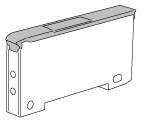
Amplifier mounting bracket
MS-DIN-4
Connector attached cable
CN-14A(-R)-C□

Connector
CN-14A
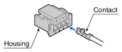
Recommended connector
Contact:
SPHD-001T-P0.5, Housing: PAP-04V-S (Manufactured by J.S.T. Mfg. Co., Ltd.)
Note:
Contact the manufacturer for details of the recommended products.
Recommended crimping tool
Model No.:
YC-610R (Manufactured by J.S.T. Mfg. Co., Ltd.)
Note:
Contact the manufacturer for details of the recommended products.
Recommended e-CON connector
Manufactured by 3M Japan Limited
Adapted connector : 37104-3122-000 FL
Please refer to "Introducing the 3M™ mini-clamp connector" for details.
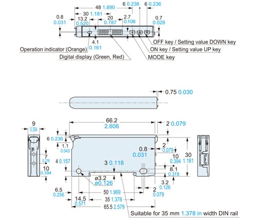
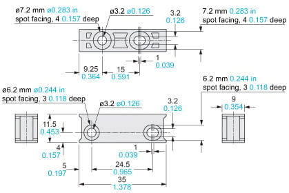
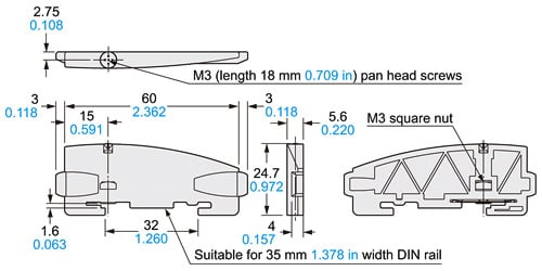
Dimensions
- Unit: mm in
FX-101□
FX-102□
Amplifier
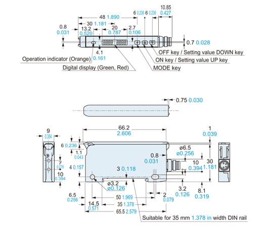
FX-101(P)-Z
FX-102(P)-Z
Amplifier
CN-14A-C□
CN-14A-R-C□
Connector attached cable (Optional, CN-14A-C2 is attached to FX-101(P)-CC2 / FX-102(P)-CC2)
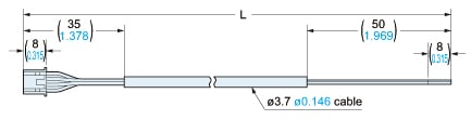
• Length L
| Model No. | Length L |
|---|---|
| CN-14A(-R)-C1 | 1,000 39.370 |
| CN-14A(-R)-C2 | 2,000 78.740 |
| CN-14A(-R)-C3 | 3,000 118.110 |
| CN-14A(-R)-C5 | 5,000 196.850 |
MS-DIN-4
Amplifer mounting bracket (Optional)
Material:PBT
MS-DIN-E
End plate (Optional)
Material:Polycarbonate
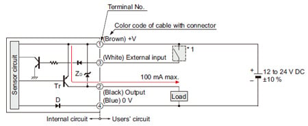
I/O Circuit and Wiring diagrams
NPN output type
FX-10□(-Z/-CC2)
I/O circuit diagram
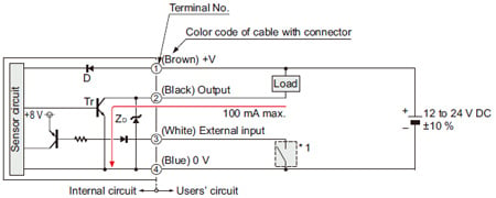
Symbols・・・
D : Reverse supply polarity protection diode
ZD: Surge absorption zener diode
Tr : NPN output transistor
Terminal arrangement diagram
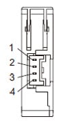
Connector type
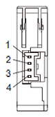
| Terminal No. | Function |
|---|---|
| 1 | +V |
| 2 | Output |
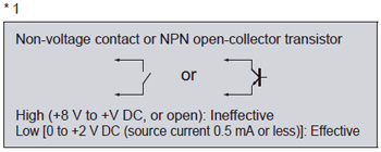
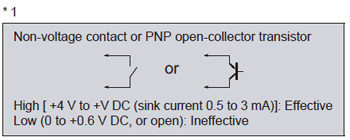
| 3 | External input |
| 4 | 0 V |
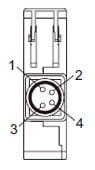
M8 plug-in connector type
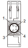
| Terminal No. | Function |
|---|---|
| 1 | +V |
| 2 | Output |
| 3 | External input |
| 4 | 0 V |
PNP output type
FX-10□P(-Z/-CC2)
I/O circuit diagram
Symbols・・・
D : Reverse supply polarity protection diode
ZD: Surge absorption zener diode
Tr : PNP output transistor
Terminal arrangement diagram
Connector type
| Terminal No. | Function |
|---|---|
| 1 | +V |
| 2 | Output |
| 3 | External input |
| 4 | 0 V |
M8 plug-in connector type
| Terminal No. | Function |
|---|---|
| 1 | +V |
| 2 | Output |
| 3 | External input |
| 4 | 0 V |
List of fibers
Fiber List
- Chemical-resistant
- Heat-resistant
- One-Touch Connection System Vacuum-resistant Fibers
- Vacuum-resistant
- Special-shaped fiber
- Metal-free
Square Head Fiber
■Thru-beam type(one pair set)
| Type | Model No. | Sensing range(mm) (Note1) | ||
|---|---|---|---|---|
| FX-101 | FX-102 | |||
| Square head | M3 | FT-R31 | 100 | 340 |
| M4 | FT-R43 | 210 | 640 | |
| FT-R41W | 250 | 710 | ||
| FT-R42W | 510 | 2,000 | ||
| FT-R44Y | 210 | 640 | ||
| M6 | FT-R60Y | 690 | 1,890 | |
■Reflective type
| Type | Model No. | Sensing range(mm) (Note1)(Note2) | ||
|---|---|---|---|---|
| FX-101 | FX-102 | |||
| Square head | M3 | FD-R31G (Discontinued products) | 45 | 150 |
| FD-R35G | 43 | 127 | ||
| FD-R32EG | 20 | 68 | ||
| FD-R33EG | 7 | 22 | ||
| FD-R34EG | 17 | 60 | ||
| M4 | FD-R41 | 60 | 170 | |
| M6 | FD-R61Y | 85 | 185 | |
Note1:Note that the sensing range of the free-cut type fiber may be reduced by 20 % max. depending on how the fiber is cut.
Note2:The sensing range is specified for white non-glossy paper.
For details of Square Head Fiber, refer to product information page.
>>Go to "Square Head Fiber"
Super Quality
■Thru-beam type (one pair set)
| Type | Model No. | Sensing range (mm) | ||
|---|---|---|---|---|
| FX-101 | FX-102 | |||
| Threaded | M3 | FT-30 | 135 | 400 |
| M4 | FT-40 | 320 | 870 | |
| Cylindrical | ø1.5 | FT-S20 | 135 | 400 |
| ø3 | FT-S30 | 320 | 870 | |
■Reflective type
| Type | Model No. | Sensing range (mm) (Note) | ||
|---|---|---|---|---|
| FX-101 | FX-102 | |||
| Threaded | M3 | FD-30 | 45 | 155 |
| M4 | FD-40 | 45 | 155 | |
| M6 | FD-60 | 140 | 420 | |
| Cylindrical | ø3 | FD-S30 | 45 | 155 |
Note:The sensing range is specified for white non-glossy paper.
For details of Super Quality Fiber, refer to product information page.
>>Go to "Super Quality Fiber"
Threaded Type
■Thru-beam type (one pair set)
| Type | Model No. | Sensing range (mm) (Note 1) | |||
|---|---|---|---|---|---|
| FX-101 | FX-102 | ||||
| Threaded | M3 | FT-32 | 1,300 | 3,600 (Note 2) | |
| FT-31 | 130 | 340 | |||
| FT-31W | 80 | 240 | |||
| M4 | FT-43 | 350 | 970 | ||
| FT-42 | 300 | 800 | |||
| FT-42W | 260 | 720 | |||
| FT-45X | 340 | 920 | |||
| Elbow | FT-R40 | 270 | 740 | ||
| M14 | Long range | FT-140 | 14,000 | 19,600 (Note 2) | |
Note 1:Note that the sensing range of the free-cut type fiber may be reduced by 20 % max. depending upon how the fiber is cut.
Note 2:The fiber cable length practically limits the sensing range.
■Reflective type
| Type | Model No. | Sensing range (mm) (Note 1, 2) | |||
|---|---|---|---|---|---|
| FX-101 | FX-102 | ||||
| Threaded | M3 | FD-34G | 29 | 90 | |
| FD-31 | 35 | 140 | |||
| FD-31W | 15 | 60 | |||
| FD-32G | 70 | 190 | |||
| FD-32GX | 75 | 210 | |||
| Ultra-small diameter | FD-EG30 | 20 | 70 | ||
| FD-EG31 | 7 | 25 | |||
| M4 | FD-41 | 35 | 140 | ||
| FD-41W | 80 | 230 | |||
| FD-42G | 70 | 190 | |||
| FD-42GW (Discontinued products) | 45 | 140 | |||
| M6 | FD-62 | 170 | 450 | ||
| FD-61 | 120 | 410 | |||
| FD-61W | 80 | 230 | |||
| FD-61G | 120 | 350 | |||
| FD-64X | 75 | 220 | |||
| Elbow | FD-R60 | 110 | 240 | ||
Note 1:Note that the sensing range of the free-cut type fiber may be reduced by 20 % max. depending upon how the fiber is cut.
Note 2:The sensing range is specified for white non-glossy paper.
For details of Threaded Type Fiber, refer to product information page.
>>Go to "Threaded Type Fiber"
Cylindrical Type
■Thru-beam type (one pair set)
| Type | Model No. | Sensing range (mm) (Note) | |||
|---|---|---|---|---|---|
| FX-101 | FX-102 | ||||
| Cylindrical | ø1 | FT-S11 | 40 | 90 | |
| ø1.5 | FT-S22 | 230 | 560 | ||
| FT-S21 | 130 | 340 | |||
| FT-S21W | 80 | 240 | |||
| ø2.5 | FT-S32 | 1,100 | 3,000 | ||
| ø3 | FT-S31W | 260 | 720 | ||
| Ultra-small diameter | ø3 | FT-E13 | 6 | 19 | |
| FT-E23 | 22 | 80 | |||
| Side-view | ø4 | FT-V40 | 1,000 | 3,100 | |
Note:Note that the sensing range of the free-cut type fiber may be reduced by 20 % max. depending upon how the fiber is cut.
■Reflective type
| Type | Model No. | Sensing range (mm) (Note 1, 2) | |||
|---|---|---|---|---|---|
| FX-101 | FX-102 | ||||
| Cylindrical | ø1.5 | FD-S21 (Discontinued products) | 25 | 70 | |
| FD-S23 | 17 | 50 | |||
| ø3 | FD-S34G | 29 | 90 | ||
| FD-S32 | 120 | 345 | |||
| FD-S32W | 80 | 230 | |||
| FD-S31 | 35 | 140 | |||
| FD-S33GW | 45 | 140 | |||
| Ultra-small diameter | ø1.5 | FD-E13 | 5 | 15 | |
| ø3 | FD-E23 | 20 | 70 | ||
Note 1:Note that the sensing range of the free-cut type fiber may be reduced by 20 % max. depending upon how the fiber is cut.
Note 2:The sensing range is specified for white non-glossy paper.
For details of Cylindrical Type Fiber, refer to product information page.
>>Go to "Cylindrical Type Fiber"
Sleeve
■Thru-beam type (one pair set)
| Type | Model No. | Sensing range (mm) (Note 1, 2) | |||
|---|---|---|---|---|---|
| FX-101 | FX-102 | ||||
| Threaded | M3 | FT-31S | 130 | 340 | |
| M4 | FT-42S | 300 | 800 | ||
| Cylindrical | Ultra-small diameter | ø3 | FT-E13 | 6 | 19 |
| FT-E23 | 22 | 80 | |||
| Side-view | ø2 | FT-V23 | 160 | 400 | |
| FT-V25 | 95 | 260 | |||
| FT-V24W | 35 | 90 | |||
| ø2.5 | FT-V30 | 180 | 480 | ||
Note 1:Note that the sensing range of the free-cut type fiber may be reduced by 20 % max. depending upon how the fiber is cut.
Note 2:The fiber cable length practically limits the sensing range.
■Reflective type
| Type | Model No. | Sensing range (mm) (Note 1, 2) | |||
|---|---|---|---|---|---|
| FX-101 | FX-102 | ||||
| Threaded | Ultra-small diameter | M3 | FD-EG30S | 20 | 70 |
| M4 | FD-41S | 35 | 140 | ||
| FD-41SW | 15 | 60 | |||
| M6 | FD-61S | 130 | 360 | ||
| Cylindrical | Ultra-small diameter | ø1.5 | FD-E13 | 5 | 15 |
| ø3 | FD-E23 | 20 | 70 | ||
| Side-view | ø3 | FD-V30 | 25 | 75 | |
| FD-V30W | 6 | 20 | |||
| ø5 | FD-V50 | 40 | 100 | ||
Note 1:Note that the sensing range of the free-cut type fiber may be reduced by 20 % max. depending upon how the fiber is cut.
Note 2:The sensing range is specified for white non-glossy paper.
For details of Sleeve Fiber, refer to product information page.
>>Go to "Sleeve Fiber"
Flat Type
■Thru-beam type (one pair set)
| Type | Model No. | Sensing range (mm) (Note) | ||
|---|---|---|---|---|
| FX-101 | FX-102 | |||
| Flat | FT-Z30H | 1,400 | 3,200 | |
| FT-Z30HW | 1,400 | 3,200 | ||
| FT-Z30E | 1,200 | 3,200 | ||
| FT-Z30EW | 1,400 | 2,600 | ||
| FT-Z30 | 710 | 2,300 | ||
| FT-Z30W | 540 | 1,800 | ||
| With boss | FT-Z20W | 280 | 730 | |
| FT-Z20HBW | 100 | 320 | ||
| FT-Z40W | 410 | 1,200 | ||
| FT-Z40HBW | 260 | 720 | ||
Note:Note that the sensing range of the free-cut type fiber may be reduced by 20 % max. depending upon how the fiber is cut.
■Reflective type
| Type | Model No. | Sensing range (mm) (Note 1, 2) | ||
|---|---|---|---|---|
| FX-101 | FX-102 | |||
| Flat | With boss | FD-Z20W | 2 to 32 | 1 to 80 |
| FD-Z20HBW | 2 to 30 | 1 to 90 | ||
| FD-Z40W | 1 to 74 | 200 | ||
| FD-Z40HBW | 1 to 90 | 0.5 to 240 | ||
Note 1:Note that the sensing range of the free-cut type fiber may be reduced by 20 % max. depending upon how the fiber is cut.
Note 2:The sensing range is specified for white non-glossy paper.
For details of Flat Type Fiber, refer to product information page.
>>Go to "Flat Type Fiber"
Narrow Beam
■Thru-beam type (one pair set)
| Type | Model No. | Sensing range (mm) (Note 1) | |
|---|---|---|---|
| FX-101 | FX-102 | ||
| Narrow beam | FT-KS40 | 2,200 | 3,600 (Note 2) |
| FT-KV40 | 2,200 | 3,600 (Note 2) | |
| FT-KV40H1 | 1,920 | 3,600 (Note 2) | |
| FT-KV40W | 2,200 | 3,600 (Note 2) | |
| FT-KV26 | 135 | 560 | |
| FT-KV26H1 | 160 | 500 | |
Note 1:Note that the sensing range of the free-cut type fiber may be reduced by 20 % max. depending upon how the fiber is cut.
Note 2:The fiber cable length practically limits the sensing range.
■Retroreflective type
| Type | Model No. | Sensing range (mm) (Note 1, 2) | ||
|---|---|---|---|---|
| FX-101 | FX-102 | |||
| With polarizing filters | FR-Z50HW | 100 to 550 | 100 to 830 | |
| Wafer mapping | FR-KZ22E | 15 to 200 | 15 to 360 | |
| Narrow beam | Top sensing | FR-KZ50H | 20 to 200 | 20 to 350 |
| Side sensing | FR-KZ50E | 20 to 200 | 20 to 350 | |
Note 1:Note that the sensing range of the free-cut type fiber may be reduced by 20 % max. depending upon how the fiber is cut.
Note 2:The sensing range is the possible setting range for the attached reflector. The fiber can detect an object less than setting range for the reflector.
■Reflective type
| Type | Model No. | Sensing range (mm) (Note) | |
|---|---|---|---|
| FX-101 | FX-102 | ||
| Long range | FD-Z50HW | 10 to 200 | 10 to 530 |
Note:Note that the sensing range of the free-cut type fiber may be reduced by 20 % max. depending upon how the fiber is cut.
For details of Narrow Beam Fiber, refer to product information page.
>>Go to "Narrow Beam Fiber"
Wide Beam
■Thru-beam type (one pair set)
| Type | Model No. | Sensing range (mm) (Note 1) | |
|---|---|---|---|
| FX-101 | FX-102 | ||
| Wide beam | FT-A32 | 3,600 (Note 2) | 3,600 (Note 2) |
| FT-A32W | 3,600 (Note 2) | 3,600 (Note 2) | |
| FT-A11 | 1,900 | 3,600 (Note 2) | |
| FT-A11W | 1,700 | 3,400 | |
| Array | FT-AL05 | 250 | 660 |
Note 1:Note that the sensing range of the free-cut type fiber may be reduced by 20 % max. depending upon how the fiber is cut.
Note 2:The fiber cable length practically limits the sensing range to 3,600 mm long.
■Reflective type
| Type | Model No. | Sensing range (mm) (Note 1, 2) | |
|---|---|---|---|
| FX-101 | FX-102 | ||
| Wide beam | FD-A16 | 120 | 240 |
| Array | FD-AL11 (Discontinued products) | 100 | 285 |
| FD-AL12 | 80 | 240 | |
Note 1:Note that the sensing range of the free-cut type fiber may be reduced by 20 % max. depending upon how the fiber is cut.
Note 2:The sensing range is specified for white non-glossy paper.
For details of Wide Beam Fiber, refer to product information page.
>>Go to "Wide Beam Fiber"
Convergent Reflective Type
■Reflective type
| Type | Model No. | Sensing range (mm) (Note 1, 2) | |
|---|---|---|---|
| FX-101 | FX-102 | ||
| Glass substrate detection | FD-L32H | 16 to 30 | 0 to 50 |
| FD-L30A | 0 to 40 | 0 to 50 | |
| FD-L31A | 5 to 30 | 4 to 33 | |
| FD-L22A (Discontinued products) | 0 to 19 | 0 to 25 | |
| FD-L24A | 0 to 19 | 0 to 21 | |
| FD-L23 (Discontinued products) | 0 to 28 | 0 to 30 | |
| FD-L25 | 0 to 25 | 0 to 30 | |
| FD-L11 | 0 to 8 | 0 to 9 | |
| FD-L10 | 0 to 4.5 | 0 to 5.5 | |
| FD-L21 | 3 to 15 | 1.5 to 16 | |
| FD-L21W | 7 to 12 | 3 to 14 | |
| General purpose | FD-L20H | 5 to 15 | 1 to 30 |
| Ultla small | FD-L12W | 1 to 4.5 | 0.5 to 7 |
| FD-L13H1 | 0 to 3 | 0 to 3.5 | |
Note 1:The sensing range is specified for transparent glass 100 x 100 x t0.7 mm (FD-L32H: R edge, FD-L21 and FD-L21W: t2 mm, FD-L13H1: 50 x 50 mm) (FD-L20H: white non-glossy paper, FD-L10: silicon wafers 100 x 100 mm).
Note 2:Note that the sensing range of the free-cut type fiber may be reduced by 20 % max. depending upon how the fiber is cut.
For details of Convergent Reflective Type Fiber, refer to product information page.
>>Go to "Convergent Reflective Type Fiber"
Retroreflective Type
■Retroreflective type
| Type | Model No. | Sensing range (mm) (Note 1, 2) | ||
|---|---|---|---|---|
| FX-101 | FX-102 | |||
| With polarizing filters | FR-Z50HW | 100 to 550 | 100 to 830 | |
| Wafer mapping | FR-KZ22E | 15 to 200 | 15 to 360 | |
| Narrow beam | Top sensing | FR-KZ50H | 20 to 200 | 20 to 350 |
| Side sensing | FR-KZ50E | 20 to 200 | 20 to 350 | |
Note 1:Note that the sensing range of the free-cut type fiber may be reduced by 20 % max. depending upon how the fiber is cut.
Note 2:The sensing range is the possible setting range for the attached reflector. The fiber can detect an object less than setting range for the reflector.
For details of Retroreflective Type Fiber, refer to product information page.
>>Go to "Retroreflective Type Fiber"
Chemical-resistant
■Thru-beam type (one pair set)
| Type | Model No. | Sensing range (mm) (Note) | |
|---|---|---|---|
| FX-101 | FX-102 | ||
| Chemical-resistant | FT-Z802Y | 520 | 3,100 |
| FT-HL80Y | 990 | 2,340 | |
| FT-L80Y | 1,100 | 2,600 | |
| FT-V80Y | 340 | 800 | |
Note:Note that the sensing range of the free-cut type fiber may be reduced by 20 % max. depending upon how the fiber is cut.
■Reflective type
| Type | Model No. | Sensing range (mm) (Note1)(Note2) | |
|---|---|---|---|
| FX-101 | FX-102 | ||
| Chemical-resistant | FD-S60Y | 140 | 300 |
Note 1:Note that the sensing range of the free-cut type fiber may be reduced by 20 % max. depending on how the fiber is cut.
Note 2:The sensing range is specified for white non-glossy paper.
For details of Chemical-resistant Fiber, refer to product information page.
>>Go to "Chemical-resistant Fiber"
Heat-resistant
■Thru-beam type (one pair set)
| Type | Heat-resistant temp. | Model No. | Sensing range (mm) (Note) | |
|---|---|---|---|---|
| FX-101 | FX-102 | |||
| Heat-resistant | 350℃ | FT-H35-M2 | 170 | 490 |
| FT-H35-M2S6 | 170 | 490 | ||
| 200℃ | FT-H20W-M1 | 100 | 300 | |
| FT-H20-M1 | 210 | 540 | ||
| 130℃ | FT-H13-FM2 | 250 | 700 | |
| Heat-resistant (joint) | 200℃ | FT-H20-J20-S | 135 | 420 |
| FT-H20-J30-S | 135 | 420 | ||
| FT-H20-J50-S | 135 | 420 | ||
| FT-H20-VJ50-S | 150 | 500 | ||
| FT-H20-VJ80-S | 150 | 500 | ||
Note:Note that the sensing range of the free-cut type fiber may be reduced by 20 % max. depending upon how the fiber is cut.
■Reflective type
| Type | Heat-resistant temp. | Model No. | Sensing range (mm) (Note 1, 2) | ||
|---|---|---|---|---|---|
| FX-101 | FX-102 | ||||
| Heat-resistant | Threaded | 350℃ | FD-H35-M2 | 75 | 280 |
| FD-H35-M2S6 | 75 | 280 | |||
| FD-H35-20S | 85 | 200 | |||
| 200℃ | FD-H20-M1 | 120 | 300 | ||
| FD-H20-21 | 90 | 280 | |||
| 130℃ | FD-H13-FM2 | 100 | 280 | ||
| Glass substrate detection convergent reflective | 300℃ | FD-H30-L32 | 2 to 9 | 0 to 17 | |
| 250℃ | FD-H25-L43 | 4 to 16 | 4 to 23 | ||
| FD-H25-L45 | 7 to 35 | 7 to 38 | |||
| 180℃ | FD-H18-L31 | 0 to 10 | 0 to 25 | ||
Note 1:The sensing range of reflective type is the value for white non-glossy paper (50 x 50 mm glass substrate for FD-H30-L32,
FD-H18-L31, transparent glass 100 x 100 x t0.7 mm for FD-H25-L43 and FD-H25-L45).
Note 2:Note that the sensing range of the free-cut type fiber may be reduced by 20 % max. depending upon how the fiber is cut.
For details of Heat-resistant Fiber, refer to product information page.
>>Go to "Heat-resistant Fiber"
One-Touch Connection System Vacuum-resistant Fibers
■Thru-beam type
| Type | Model No. | Sensing range (mm)(Note 1) | ||
|---|---|---|---|---|
| FX-101 | FX-102 | |||
| Vacuum- resistant | Thru-beam | FT-40V | 110 | 280 |
(Note 1):Atmospheric side fiber, FT-J9 (optional) is free-cut type.
Note that the sensing range of the free-cut type fiber may be reduced by 20 % max. depending upon how the fiber is cut.
■Reflective type
| Type | Model No. | Sensing range(mm) (Note 1)(Note 2) | ||
|---|---|---|---|---|
| FX-101 | FX-102 | |||
| Vacuum- resistant | Long range reflective | FD-KZ50V | 25 to 80 | 10 to 220 |
| Convergent reflective | FD-L10V | 2.5 to 6.5 | 0 to 11 | |
(Note 1):The sensing range is the value for transparent glass 100 × 100 × t0.7 mm 3.937 × 3.937 × t0.028 in.
(Note 2):Atmospheric side fiber, FT-J9 (optional) is free-cut type.
Note that the sensing range of the free-cut type fiber may be reduced by 20 % max. depending upon how the fiber is cut.
For details of One-Touch Connection System Vacuum-resistant Fibers, refer to product information page.
>>Go to "One-Touch Connection System Vacuum-resistant Fibers"
Vacuum-resistant
■Thru-beam type (one pair set)
| Type | Model No. | Sensing range (mm) | ||
|---|---|---|---|---|
| FX-101 | FX-102 | |||
| Vacuum-resistant | Thru-beam | FT-H30-M1V-S | 110 | 280 |
■Reflective type
| Type | Model No. | Sensing range (mm) (Note) | ||
|---|---|---|---|---|
| FX-101 | FX-102 | |||
| Vacuum-resistant | Reflective | FD-H30-KZ1V-S | 25 to 80 | 10 to 220 |
| Convergent reflective | FD-H30-L32V-S | 2.5 to 6.5 | 0 to 11 | |
Note:The sensing range of reflective type is the value for transparent glass 100 x 100 x t0.7 mm.
For details of Vacuum-resistant Fiber, refer to product information page.
>>Go to "Vacuum-resistant Fiber"
Special-shaped fiber

| Model No. | Sensing range (mm) | ||
|---|---|---|---|
| FX-101 | FX-102 | ||
| Heat-resistant U-shaped type | FT-PK40H1 | 5(fixed)) | 5(fixed)) |
Note: Note that the sensing range of the free-cut type fiber may be reduced by 20 % max. depending upon how the fiber is cut.
For details of Special-shaped fiber, refer to product information page.
>>Go to "Special-shaped fiber"
Metal-free
■Thru-beam type (one pair set)
| Type | Model No. | Sensing range (mm) (Note) | ||
|---|---|---|---|---|
| FX-101 | FX-102 | |||
| Threaded | M4 | FT-41 | 300 | 800 |
Note:Note that the sensing range of the free-cut type fiber may be reduced by 20 % max. depending upon how the fiber is cut.
■Reflective type
Note 1:Note that the sensing range of the free-cut type fiber may be reduced by 20 % max. depending upon how the fiber is cut.
Note 2:The sensing range is specified for white non-glossy paper.
For details of Metal-free Fiber, refer to product information page.
>>Go to "Metal-free Fiber"
Using in combination with the FX-300 / FX-410 series
- The FX-100 series does not use the horizontal connectors that are used with the FX-300 / FX-410 series. Please note that horizontal connection cannot be performed using a connector attached cable. In addition, the optical communication function is not equipped on the FX-100 series, so it is unable to perform interference prevention for use with the FX-300 / FX-410 series.
If using the FX-100 series together with the FX-300 / FX-410 series side-by-side, please set the same models together in groups.
Mounting
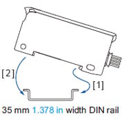
<When using a DIN rail>
How to mount the amplifier
[1]Fit the rear part of the mounting section of the amplifier on a 35 mm 1.378 in width DIN rail.
[2]Press down the rear part of the mounting section of the unit on the 35 mm 1.378 in width DIN rail and fit the front part of the mounting section to the DIN rail.
How to remove the amplifier
[1]Push the amplifier forward.
[2]Lift up the front part of the amplifier to remove it.
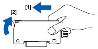
Note:Take care that if the front part is lifted without pushing the amplifier forward, the hook on the rear portion of the mounting section is likely to break.
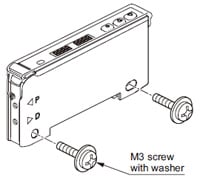
<When using screws with washers>
- Use M3 screws with washers for mounting. The tightening torque should be 0.5 N·m or less.
Wiring
- Make sure that the power supply is OFF while adding or removing the amplifiers.
- Note that if a voltage exceeding the reted range is applied, or if an AC power supply is directly connected, the product may get burnt or damaged.
- Note that short-circuit of the load or wrong wiring may burn or damage the product.
- Do not run the wires together with high-voltage lines or power lines, or put them in the same raceway. This can cause malfunction due to induction.
- Verify that the supply voltage variation is within the rating.
- If power is supplied from a commercial switching regulator, ensure that the frame ground (F.G.) terminal of the power supply is connected to an actual ground.
- In case noise generating equipment (switching regulator, inverter motor, etc.) is used in the vicinity of this product, connect the frame ground (F.G.) terminal of the equipment to an actual ground.
- Make sure to use the quick-connection cable (optional) for the connection of the controller.
Extension up to total 100 m 328.084 ft is possible with 0.3 mm2 or more, cable. However, in order to reduce noise, make the wiring as short as possible.
Part description
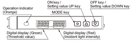
Setting mode
- Setting mode appears after the MODE key is pressed for 2 sec. in RUN mode.
| Setting item | Factory setting | Description |
|---|---|---|
| Teaching mode |
| Threshold value can be set in 2-point teaching, limit teaching, or full-auto teaching. |
| Output operation setting |
[Dark-ON] | Light-ON or Dark-ON can be set. |
| Timer operation setting |
[Without timer] | Without timer, ON delay timer, or OFF delay timer can be set. |
| Timer delays setting |
[ON-delay timer: 10 ms]
[OFF-delay timer: 10 ms] | When setting ON delay timer or OFF delay timer in the timer operation setting mode, timer delays can be set. ・When timer is not set, this mode is not displayed. |
| Emission amount setting |
*[Level 3] | In case incident light intensity is saturated, emission amount can be reduced. |
| Emission frequency setting | FX-101□
[0 (Response time:250 μs or less)] FX-102□
[1 (Response time:2.5 ms or less)] | When using the fiber heads in parallel, interference can be prevented by setting different emission frequency. However, when emission frequency 0 is set, interference cannot be prevented. Response time corresponds to emission frequency. |


PRO mode
- PRO mode appears after the MODE key is pressed for 4 sec. in RUN mode.
| Setting item | Factory setting | Description |
|---|---|---|
| Shift setting | [Shift amount 15 %] | Shift amount can be selected from 0 to 80 % in the limit teaching. Select 0 % when it is desired to set the present incident light intensity as a threshold value. |
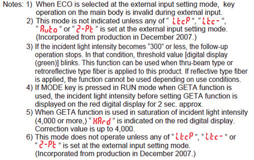
| External input setting | [Emission halt] | External input can be selected from emission halt, limit teaching [+], limit teaching [-], full-auto teaching, ECO (Note 1), 2-point teaching or emission amount test. When setting the incident light intensity test “ |
| Threshold value-storing setting mode (Note 2) | Threshold value set at the limit teaching, full-auto teaching or 2-point teaching by external input is stored. When selecting Auto in the emission amount setting mode, the set emission amount level is also stored. | |
| Threshold value follow-up cycle setting (Note 3) | When incident light intensity exceeds threshold value, this mode can change the threshold value with each set cycle depending on variations of the incident light intensity. The follow-up shift amount is same as the one set in the shift setting mode. However, the threshold value is not stored. | |
| GETA function setting (Note 4, 5) | Variations can be reduced by correcting the present incident light intensity in each amplifier to a target value. Target value to offset incident light intensity can be selected from 0 to 2,000 by 100 unit each. For example, if the target value is set to 2,000 when the incident light intensity is 1,500, the incident light intensity becomes 2,000. | |
| ECO setting | It is possible to light up / turn off the digital display. When ECO setting mode is ON, the display turns off in 20 sec. approx. in RUN mode. To light up the display again, press any key for 2 sec. or more. | |
| Digital display inversion setting | Digital display can be inverted. | |
| Threshold value margin setting | Margin for threshold value to the present incident light intensity can be checked. When there is no margin, it is possible to make the digital display blink. : | |
| Setting copy | The settings of the master side amplifier can be copied to the slave side amplifier. For details, refer to “Setting copy function”. | |
| Reset | Returns to default settings (factory settings.) |
Setting copy function
Refer to the "Instruction Manual" for details.
Others
- This product has been developed / produced for industrial use only.
- Do not use during the initial transient time (0.5 sec.) after the power supply is switched on.
- Take care that the product is not directly exposed to fluorescent lamp from a rapid-starter lamp, a high frequency lighting device or sunlight etc., as it may affect the sensing performance.
- This product is suitable for indoor use only.
- Avoid dust, dirt, and steam.
- Take care that the product does not come in contact with oil, grease, organic solvents, such as thinner, etc., strong acid or alkaline.
- This product cannot be used in an environment containing inflammable or explosive gases.
- Never disassemble or modify this product.
- EEPROM is adopted to this product. It is not possible to conduct teaching 100 thousand times or more, because of the EEPROM’s lifetime.
Quick setting function
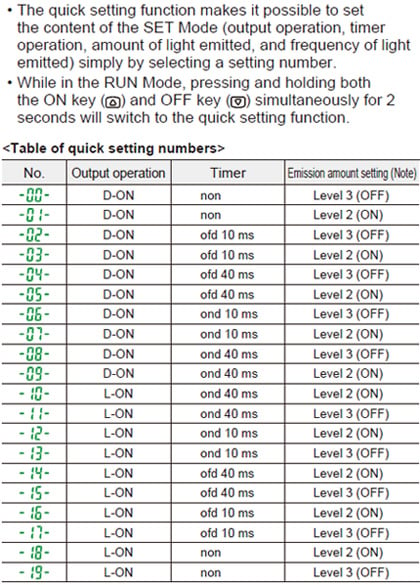
Note:The emission amount of Level 2 (ON) is about 40% of that of Level 3 (OFF).
Code setting function