NA40-8|40 mm Beam Pitch General Purpose Area Sensor NA40(Discontinued)
Download
Discontinued
Last time buy (JST)
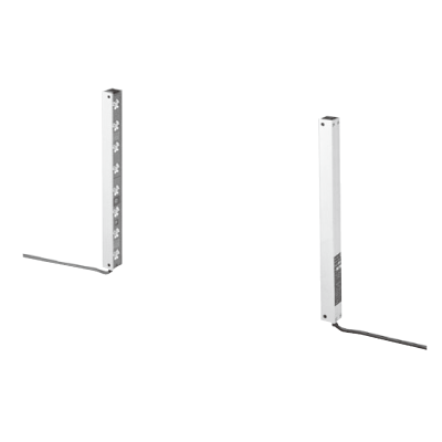
*Photo may vary from actual product.
This product has been confirmed that it does not contain the 6 substances specified in EU RoHS Directive 2011/65/EU and the 4 substances specified in 2015/863/EU.
Spec Detail
| Item | Specifications |
|---|---|
| Part Number | NA40-8 |
| Product Number | NA40-8 |
| Products Name | 40 mm Beam Pitch General Purpose Area Sensor |
| Product details | Area sensor |
| The price of the product | Please contact our office |
| Sensing height | 280 mm 11.024 in |
| Sensing range | 5 m 16.404 ft |
| Beam pitch | 40 mm 1.575 in |
| Sensing object | ø60 mm ø2.362 in or more opaque object |
| Supply voltage | 12 to 24 V DC ±10 % Ripple P-P 10 % or less |
| Current consumption | Emitter: 30 mA or less Receiver: 60 mA or less |
| Sensing output | NPN open-collector transistor • Maximum sink current: 100 mA • Applied voltage: 30 V DC or less (between sensing output and 0 V) • Residual voltage: 1.6 V or less (at 100 mA sink current) |
| Sensing output:Output operation | ON when all beam channels are received / OFF when one or more beam channels are interrupted |
| Sensing output:Short-circuit protection | Incorporated |
| Self-diagnosis output | NPN open-collector transistor • Maximum sink current: 50 mA • Applied voltage: 30 V DC or less (between self-diagnosis output and 0 V) • Residual voltage: 1.6 V or less (at 50 mA sink current) |
| Self-diagnosis output:Output operation | OFF when unstable light received condition continues for 5 sec. or more, or the output transistor fails |
| Self-diagnosis output:Short-circuit protection | Incorporated |
| Response time | 12 ms or less |
| Indicator | Incorporated with the three color indicators on the receiver • Sensing output operation indicator: Red LED (lights up when one or more beam channels are interrupted) • Stable incident beam indicator: Green LED (lights up when all beam channels are received stably) • Unstable incident beam indicator: Yellow LED (lights up when one or more beam channels are received unstably) * When the output transistor fails, the three color indicators blink simultaneously. |
| Interference prevention function | Incorporated (Two units of sensors can be mounted close together.) |
| Protection | IP65 (IEC) |
| Ambient temperature | –10 to +50 ℃ +14 to +122 ℉ (No dew condensation or icing allowed), Storage: –10 to +60 ℃ +14 to +140 ℉ |
| Ambient humidity | 35 to 85 % RH, Storage: 35 to 85 % RH |
| Ambient illuminance | Incandescent light: 3,500 ℓx or less at the light-receiving face |
| Voltage withstandability | 1,000 V AC for one min. between all supply terminals connected together and enclosure |
| Insulation resistance | 20 MΩ, or more, with 500 V DC megger between all supply terminals connected together and enclosure |
| Vibration resistance | 10 to 55 Hz frequency, 1.5 mm 0.059 in double amplitude in X, Y and Z directions for two hours each |
| Shock resistance | 100 m/s2 acceleration (10 G approx.) in X, Y and Z directions three times each |
| Emitting element | Infrared LED (synchronized scanning system) |
| Material | Protection enclosure: Aluminum Unit case: ABS Front cover: Acrylic Lens: Acrylic |
| Cable | 0.5 mm2 4-core (emitter: 3-core) cabtyre cable, 0.5 m 1.640 ft long, with a round connector at the end * Use together with the optional mating cable |
| Cable extension | Extension up to total 100 m 328.084 ft is possible, for both emitter and receiver, with 0.5 mm2, or more, cable. (However, the interference prevention wire can extend up to 20 m 65.617 ft between two emitters.) |
| Weight(Total weight of emitter and receiver) | 630 g approx. |
| Accessories | MS-NA40-1 (Sensor mounting bracket): 1 set for emitter and receiver Adjusting screwdriver: 1 pc. |