Basic Information

Our Mission is to Maximize Customer Benefits with Outstanding Products Enhancing Advanced Functionality and Performance.
The Answer is FP0R, Superior to Basic Ultra-compact Models.


UL Recognition : AFP0RC10CRM, AFP0RC10RM, AFP0RC14CRM, AFP0RC14RM, AFP0RE16RM and AFP0RE8RM only
UL Listing : Excluding above
Features
Makeover for FP0R analog units.
Greatly improved performance, extended functions
●Higher resolution: 14 bits (previously 12 bits)
Higher resolution: 12 bits → 14 bits (analog input, output)
Higher precision: ±0.6 % → ±0.2 % (at 25 ℃ 77 ℉)
Achieve high-resolution analog control in applications such as film winding, tension control, winding speed control, and other operations.

●Enables move to multi-channel systems and optimization
Up to 8-channel input: Easier transition to multi-channel systems. And, with free combination of input/output, systems can be optimized.
●Select among 6 input ranges (analog input unit) and 6 output ranges
Five selectable input settings: ±10 V, ±5 V, 0 to +10 V, 0 to +5 V, 0 to 20 mA
Sixth output setting: ±10 V, ±5 V, 0 to +10 V, 0 to +5 V, 0 to 20 mA, 4 to 20 mA
With ±10 V support it is even possible to control the rotation of motors.
●Can also be used with other PLCs outside the FP0R series
Use in connection with FP0H, FP-XH, and FP-X0 series PLCs is possible.

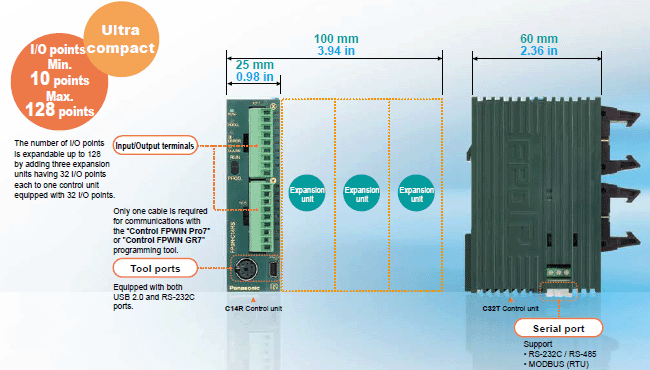
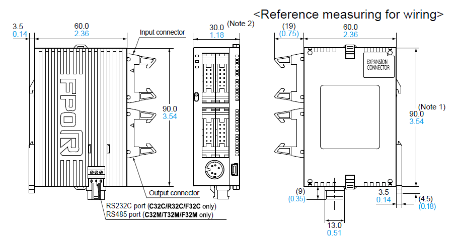
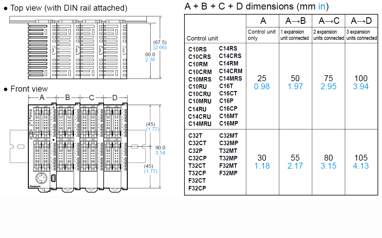
The control unit is small at 90 mm 3.54 in in height and 25 mm 0.98 in in width.
Even when expanded with three expansion units, the total width only 100 mm 3.94 in.
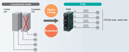
Multi-axis (4-axis) control is available without expansion units.
Built-in pulse outputs for four axes (50 kHz max. each)
Full-fledged positioning functions
Up to 8-channel input: Easier transition to multi-channel systems And, with free combination of input/output, systems can be optimized.
Built-in high speed counter
A single-phase 6 points or 4 points (50 kHz max. each), 2-phase 3 points or 2 points (15 kHz max. each) high speed counter is built in.
Ultra-high speed processing
Ultra-high speed: 80 ns/step (ST instructions)
* Within a range of 0 to 3,000 steps. Processing of the 3,001st and later steps is 580 ns, 1.5 times faster than the conventional model.
Note: Unit expansion increases the base time.

Without expansion units: 0.2 ms or lessWith expansion units: 0.2 ms or less + (1 x Number of expansion units) ms
Battery-less automatic backup of all data
The F type (FP0R-F32) has a built-in FeRAM, which is a cutting-edge device that allows the automatic saving of all data without a backup battery.
● There is no need to worry about data loss after a long vacation.
● Battery replacement is no longer necessary when shipping or
transferring the unit overseas.
● Replacement of equipment and restoration of idle equipment is easy.
● The unit can be powered off flexibly on weekends or at other
non-operating times, promoting energy saving.
Large capacity independent comment memory
Program maintenance and management become easier.
USB tool port provided as standard equipment
Programming work becomes simpler, easier, and quicker, improving the production efficiency.
Large capacity program
Program capacity: 32 k steps * 1, Data register: 32 k words * 1
*1: C10, C14 or C16 control unit: Program capacity of 16 k steps and data register of 12 k words
POSITIONING
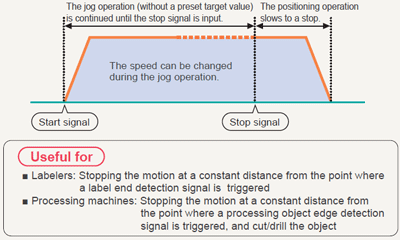
■Jog positioning control (F171 instruction)
The motion can be started without a preset target value. When a stop signal is input, the target value is set, and the motion is slowed to a stop.
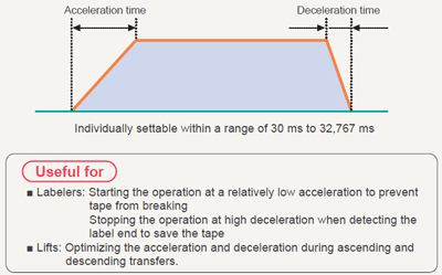
■Individual settings for acceleration and deceleration
(available for F171, F172, and F174 instructions)
The acceleration time and deceleration time can be individually set.
■Changing the speed
(available for F171 and F172 instructions)
The target speed can be changed by an external signal input during the jog operation or trapezoidal control operation.

■Measuring the pulse frequency (F178 instruction)
Pulses input in a specified period by a single instruction are counted, and the frequency is calculated.

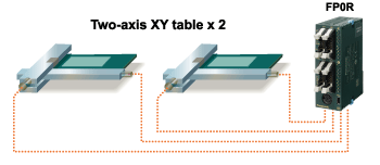
■Built-in 4-axis pulse outputs (Transistor output type)
Two sets can simultaneously undergo two-axis linear interpolation.
No complicated speed calculation or programming is required.
Two-axis linear interpolation is available by using the F175 dedicated instruction. Two sets such as two X-Y tables, for example, can be simultaneously controlled.
■High-speed counters and pulse outputs
Ladder programs can be combined to create an application for counting pulse signals from the encoder through the high-speed counter input and adjusting the pulse output frequency based on the count to synchronize the slave axis speed with the master axis speed.
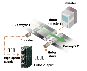
In the above figure, the speed of conveyor 1, which is inverter-controlled, is measured based on the encoder pulse count, and pulses are output to the slave motor (for jog operation) according to the measured speed in order to synchronize the speed of conveyor 2.
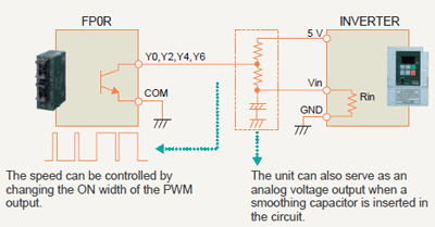
■Built-in multipoint PWM outputs (4 channels)
The pulse output port of FP0R can also serve as a PWM output port. One of the application examples is an analog voltage output, which can be used for inverter speed control.
NETWORK
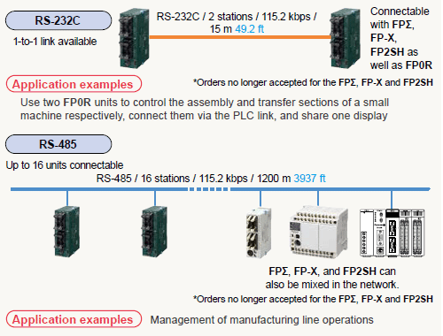
■PLC link (MEWNET-W0)
Contact data can be shared among up to 16 PLC units, including FP0R, FPΣ, FP-X, FP2/FP2SH, and a mixture of them, without the need for programs.
■FP Web-Server2
The FP0R operation status can be monitored on a Web browser.
The FP0R operation status can be monitored on a Web browser by connecting FP Web-Server2 and FP0R via RS-232C and making required settings using dedicated software (FP Web Configurator Tool 2).
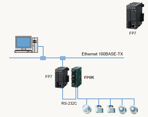
■RS-485 serial communication
Compatible with both Modbus master and slave RTU.
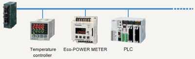
This feature expands applications for the eco-conscious business field, and is ideal for the control of air conditioners, temperature, and electrical power.
●Control of 31 servo motor shafts
Can be connected using a MINAS A6 series Panasonic Industry servo motor and Modbus RTU. Motor control and monitoring are achieved via minimal wiring.
Motor information collection and adjustment are possible from the host PC via Modbus RTU communication.
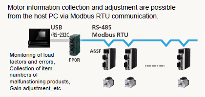
FP0R motor control specifications
| Conventional model | Latest model | |
|---|---|---|
| FP0R pulse output | FP0R & MINAS A6 Modbus | |
| Control capability | 50 kHz | Infinite* |
| Max. number of controllable shafts | 4 shafts | 31 shafts |
* No limits apply for serial communication. Resolutions is decided by setting on the amplifier side.
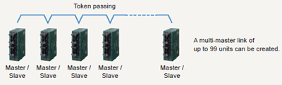
●Up to 99 units can be connected.
When 17 or more FP series units need to be linked, you can link up to 99 units by using the Modbus function instead of MEWNET-W0. Since each FP0R unit can be either a master or a slave, a multi-master link can be created by passing a token from a user program.
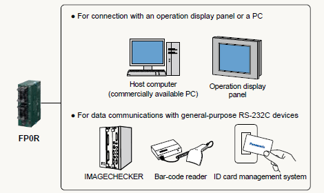
■RS-232C general-purpose serial communications
The control unit has an RS-232C port for serial communications.
The RS-232C port allows for direct connection to an operation display panel or a PC. Also, it facilitates bi-directional data communications with bar-code readers and other RS-232C devices.
* The port block has S, R, and G terminals for connection. Operation display panels can also be connected to the tool port.
* Both the relay output and transistor output types of control unit equipped with an RS-232C port are available.
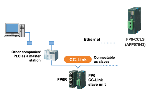
■CC-Link slave unit
This unit is compatible with CC-Link, which is an open network, and capable of reading/writing four-word data through a maximum of 16 input and 16 output points.
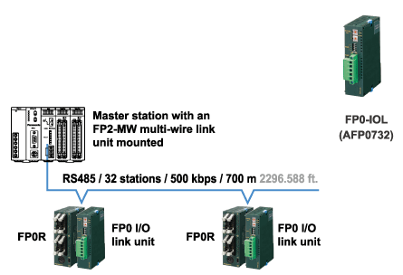
■I/O link unit
This link unit enables FP0R to serve as a slave station of MEWNET-F (remote I/O system) and exchange I/O data from 32 input points and 32 output points with a master station without the need for programs.
OTHER USEFUL FUNCTIONS
■Program protection
Program upload protection setting
User programs can be protected from unauthorized copying by disabling program upload using our software, FPWIN. This function is useful for users who manage original programs on a PC.

Eight-character password
Since uppercase and lowercase alphanumeric characters can be used, there are approx. 218 trillion possible password combinations.
If an incorrect password is entered three times in a row, a cold reboot is required.
This function is useful for users who upload programs from FP0R.
■Temperature controller
・A temperature control program can be written in only one line by using a PID instruction (F356 EZPID), facilitating temperature control programming by a PLC, which had previously been considered difficult.
・Available in two models: 4-channel and 8-channel types, supporting K, J, T, and R ranges. Up to three units can be connected, allowing high-accuracy multi-point PID control of a maximum of 24 channels.
■Built-in real-time clock (T type only)
The clock allows for year, month, day, hour, minute, and second data processing. The clock data can be linked to periodic monitoring of production data and operation status, and the management of error history records.
■Interrupt input
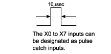
This function takes in input signals at high speed regardless of the scan time and instantly executes the interrupt program. This is useful for high-accuracy positioning control or control of defective item ejector valves. The X0 to X7 inputs can be designated as interrupt inputs (C10: X0 to X5).
■Pulse catch
This function can take in 10 μs short pulse inputs and is therefore ideal for taking in signals from a sensor to detect small components.
■Debugging
The trace function records contact ON/OFF status and data changes per each scan and allows them to be displayed in a graph on the time chart in the Control FPWIN GR7 programming software.

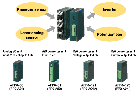
■Analog I/O
The lineup includes a compact analog I/O unit with one analog output and two analog input channels, an A/D converter unit with eight analog input channels, and a D/A converter unit with four analog output channels. Communication using up to 24 channels is possible. Both the compact body size and the high input/output resolution of 1/4,000 (12 bits) have been achieved.
The DIP switches in the unit cover a variety of input/output ranges and are user-friendly.
■EEPROM data saving (F12 and P13 instructions)
All FP0R series models are equipped with EEPROM, which can electrically rewrite data and retain data without the need for voltage supply. Setting data and production result data can be written and saved by the P13 instruction, and read out by the F12 instruction when necessary.

■Program download in RUN mode (Comment writable)
Even while the equipment is operating with FP0R in RUN mode, a whole program edited offline can be downloaded to FP0R, and comments can be written simultaneously.
Programs can be changed without stopping a running production line.

Push-in terminal block type has been released.
The push-in terminal blocks offer:
・Reduced wiring effort
・Spring mechanism that prevents loosening!
Units
- Control units
- Expansion units
- Intelligent units
- Link and Communication units[Units in common with FP0]
- Discontinued products
Control units
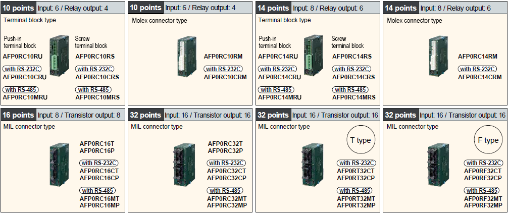
Note: The picture of terminal block type shows the screw terminal block type as a representative.
| Product name | Built-in memory (Program capacity) | Specifications | Part Number | |||||
|---|---|---|---|---|---|---|---|---|
| Number of I/O points | Power supply voltage | Input | Output | Connection type | ||||
| FP0R-C10 Control Unit | EEPROM (16 k steps) | 10 | Input: 6 Output: 4 | 24 V DC | 24 V DC Sink/Source (±common) | Relay: 2 A | Push-in terminal block |  AFP0RC10RU |
| Screw terminal block | AFP0RC10RS | |||||||
| Molex connector | AFP0RC10RM | |||||||
| FP0R-C10 Control Unit with RS-232C port | EEPROM (16 k steps) | 10 | Input: 6 Output: 4 | 24 V DC | 24 V DC Sink/Source (±common) | Relay: 2 A | Push-in terminal block | AFP0RC10CRU |
| Screw terminal block | AFP0RC10CRS | |||||||
| Molex connector | AFP0RC10CRM | |||||||
| FP0R-C10 Control Unit with RS-485 port | EEPROM (16 k steps) | 10 | Input: 6 Output: 4 | 24 V DC | 24 V DC Sink/Source (±common) | Relay: 2 A | Push-in terminal block | AFP0RC10MRU |
| Screw terminal block | AFP0RC10MRS | |||||||
| FP0R-C14 Control Unit | EEPROM (16 k steps) | 14 | Input: 8 Output: 6 | 24 V DC | 24 V DC Sink/Source (±common) | Relay: 2 A | Push-in terminal block | AFP0RC14RU |
| Screw terminal block | AFP0RC14RS | |||||||
| Molex connector | AFP0RC14RM | |||||||
| FP0R-C14 Control Unit with RS-232C port | EEPROM (16 k steps) | 14 | Input: 8 Output: 6 | 24 V DC | 24 V DC Sink/Source (±common) | Relay: 2 A | Push-in terminal block | AFP0RC14CRU |
| Screw terminal block | AFP0RC14CRS | |||||||
| Molex connector | AFP0RC14CRM | |||||||
| FP0R-C14 Control Unit with RS-485 port | EEPROM (16 k steps) | 14 | Input: 8 Output: 6 | 24 V DC | 24 V DC Sink/Source (±common) | Relay: 2 A | Push-in terminal block | AFP0RC14MRU |
| Screw terminal block | AFP0RC14MRS | |||||||
| FP0R-C16 Control Unit | EEPROM (16 k steps) | 16 | Input: 8 Output: 8 | 24 V DC | 24 V DC Sink/Source (±common) | Transistor NPN: 0.2 A | MIL connector | AFP0RC16T |
| Transistor PNP: 0.2 A | AFP0RC16P | |||||||
| FP0R-C16 Control Unit with RS-232C port | EEPROM (16 k steps) | 16 | Input: 8 Output: 8 | 24 V DC | 24 V DC Sink/Source (±common) | Transistor NPN: 0.2 A | MIL connector | AFP0RC16CT |
| Transistor PNP: 0.2 A | AFP0RC16CP | |||||||
| FP0R-C16 Control Unit with RS-485 port | EEPROM (16 k steps) | 16 | Input: 8 Output: 8 | 24 V DC | 24 V DC Sink/Source (±common) | Transistor NPN: 0.2 A | MIL connector | AFP0RC16MT |
| Transistor PNP: 0.2 A | AFP0RC16MP | |||||||
| FP0R-C32 Control Unit | EEPROM (32 k steps) | 32 | Input: 16 Output: 16 | 24 V DC | 24 V DC Sink/Source (±common) | Transistor NPN: 0.2 A | MIL connector | AFP0RC32T |
| Transistor PNP: 0.2 A | AFP0RC32P | |||||||
| FP0R-C32 Control Unit with RS-232C port | EEPROM (32 k steps) | 32 | Input: 16 Output: 16 | 24 V DC | 24 V DC Sink/Source (±common) | Transistor NPN: 0.2 A | MIL connector | AFP0RC32CT |
| Transistor PNP: 0.2 A | AFP0RC32CP | |||||||
| FP0R-C32 Control Unit with RS-485 port | EEPROM (32 k steps) | 32 | Input: 16 Output: 16 | 24 V DC | 24 V DC Sink/Source (±common) | Transistor NPN: 0.2 A | MIL connector | AFP0RC32MT |
| Transistor PNP: 0.2 A | AFP0RC32MP | |||||||
| FP0R-T32 Control Unit with RS-232C port and Real-time clock function | EEPROM (32 k steps) | 32 | Input: 16 Output: 16 | 24 V DC | 24 V DC Sink/Source (±common) | Transistor NPN: 0.2 A | MIL connector | AFP0RT32CT |
| Transistor PNP: 0.2 A | AFP0RT32CP | |||||||
| FP0R-T32 Control Unit with RS-485 port and Real-time clock function | EEPROM (32 k steps) | 32 | Input: 16 Output: 16 | 24 V DC | 24 V DC Sink/Source (±common) | Transistor NPN: 0.2 A | MIL connector | AFP0RT32MT |
| Transistor PNP: 0.2 A | AFP0RT32MP | |||||||
| FP0R-F32 Control Unit with RS-232C port and Battery-less automatic all data backup function | EEPROM (32 k steps) | 32 | Input: 16 Output: 16 | 24 V DC | 24 V DC Sink/Source (±common) | Transistor NPN: 0.2 A | MIL connector | AFP0RF32CT |
| Transistor PNP: 0.2 A | AFP0RF32CP | |||||||
| FP0R-F32 Control Unit with RS-485 port and Battery-less automatic all data backup function | EEPROM (32 k steps) | 32 | Input: 16 Output: 16 | 24 V DC | 24 V DC Sink/Source (±common) | Transistor NPN: 0.2 A | MIL connector | AFP0RF32MT |
| Transistor PNP: 0.2 A | AFP0RF32MP | |||||||
Expansion units
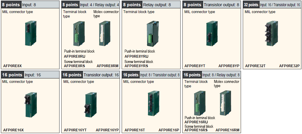
Note: The picture of terminal block type shows the screw terminal block type as a representative.
| Product name | Specications | Part number | |||||
|---|---|---|---|---|---|---|---|
| Number of I/O points | Rated voltage | Input | Output | Connection type | |||
| FP0R-E8 Expansion Unit | 8 | Input: 8 | - | 24 V DC Sink/Source (±common) | - | MIL connector | AFP0RE8X |
| 8 | Input: 4 Output: 4 | 24 V DC | 24 V DC Sink/Source (±common) | Relay: 2 A | Push-in terminal block | AFP0RE8RU | |
| Screw terminal block | AFP0RE8RS | ||||||
| Molex connector | AFP0RE8RM | ||||||
| 8 | Output: 8 | 24 V DC | - | Relay: 2 A | Push-in terminal block | AFP0RE8YRU | |
| Screw terminal block | AFP0RE8YRS | ||||||
| 8 | Output: 8 | - | - | Transistor NPN: 0.3 A | MIL connector | AFP0RE8YT | |
| 8 | Output: 8 | - | - | Transistor PNP: 0.3 A | MIL connector | AFP0RE8YP | |
| FP0R E16 Expansion Unit | 16 | Input: 16 | - | 24 V DC Sink/Source (±common) | - | MIL connector | AFP0RE16X |
| 16 | Input: 8 Output: 8 | 24 V DC | 24 V DC Sink/Source (±common) | Relay: 2 A | Push-in terminal block | AFP0RE16RU | |
| Screw terminal block | AFP0RE16RS | ||||||
| Molex connector | AFP0RE16RM | ||||||
| 16 | Input: 8 Output: 8 | - | 24 V DC Sink/Source (±common) | Transistor NPN: 0.3 A | MIL connector | AFP0RE16T | |
| 16 | Input: 8 Output: 8 | - | 24 V DC Sink/Source (±common) | Transistor PNP: 0.3 A | MIL connector | AFP0RE16P | |
| 16 | Output: 16 | - | - | Transistor NPN: 0.3 A | MIL connector | AFP0RE16YT | |
| 16 | Output: 16 | - | - | Transistor PNP: 0.3 A | MIL connector | AFP0RE16YP | |
| FP0R E32 Expansion Unit | 32 | Input: 16 Output: 16 | - | 24 V DC Sink/Source (±common) | Transistor NPN: 0.3 A | MIL connector | AFP0RE32T |
| 32 | Input: 16 Output: 16 | - | 24 V DC Sink/Source (±common) | Transistor PNP: 0.3 A | MIL connector | AFP0RE32P | |
Intelligent units
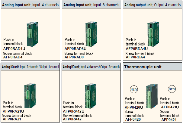
Note: The picture of terminal block type shows the screw terminal block type as a representative.
Easy backward compatibility
Use compatibility mode to retain existing ladder programming.
You can use a DIP switch to enable compatibility mode, which allows operation at 12-bit resolution (using program resources).
■PREVIOUS MODEL SUBSTITUTION
| Analog type | Previous model | New model | |
|---|---|---|---|
| Input | - | AFP0RAD4 or AFP0RAD4U | |
| AFP0401 | AFP0RAD8 or AFP0RAD8U | ||
| Output | Voltage | AFP04121 | AFP0RDA4 or AFP0RDA4U |
| Current | AFP04123 | ||
| Input / Output | AFP0480 | AFP0RA21 or AFP0RA21U | |
| - | AFP0RA42 or AFP0RA42U | ||
| Product name | Number of channels | Connection type | Part No. |
|---|---|---|---|
| FP0R Analog input unit | Input: 4 channels | Push-in terminal block | AFP0RAD4U |
| Screw terminal block | AFP0RAD4 | ||
| Input: 8 channels | Push-in terminal block | AFP0RAD8U | |
| Screw terminal block | AFP0RAD8 | ||
| FP0R Analog I/O unit | Input: 2 channels / Output: 1 channel | Push-in terminal block | AFP0RA21U |
| Screw terminal block | AFP0RA21 | ||
| Input: 4 channels / Output: 2 channels | Push-in terminal block | AFP0RA42U | |
| Screw terminal block | AFP0RA42 | ||
| FP0R Analog output unit | Output: 4 channels | Push-in terminal block | AFP0RDA4U |
| Screw terminal block | AFP0RDA4 | ||
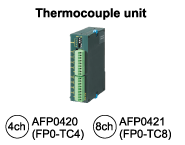
| FP0 Thermocouple Unit | K, J, T and R thermocouple, Resolution: 0.1 ℃, 4ch | Push-in terminal block | AFP0420U |
| Screw terminal block | AFP0420 | ||
| K, J, T and R thermocouple, Resolution: 0.1 ℃, 8ch | Push-in terminal block | AFP0421U | |
| Screw terminal block | AFP0421 |
Link and Communication units[Units in common with FP0]

| Product name | Specications | Power supply voltage | Product number | Part number |
|---|---|---|---|---|
| FP0 CC-Link Slave Unit | This unit is for making the FP0 function as a slave station of the CC-Link. Only one unit can be connected to the furthest right edge of the FP0 expansion bus. Note : Accuracy will change if an FP0 thermocouple unit is used at the same time. For details, please refer to the catalog or to the CC-Link Unit manual. | 24 V DC | FP0-CCLS | AFP07943 |
Additional Notes [Applicable to control units, expansion units, and intelligent units]
- Power supply cables are included with units that have rated voltage indicated
‐Control units, expansion units (relay output only), analog output units, CC-Link slave units - For the push-in terminal block type and screw terminal block type, Phoenix Contact connectors are included.
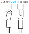
A 2.5 mm (0.098 in) wide screwdriver is required for wiring the screw terminal block type.
Please prepare a dedicated terminal block screwdriver (Phoenix Contact part number SZS 0,4X2,5) or equivalent.
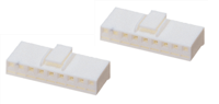
When using ferrule terminals, refer to "Cautions For Use" for applicable terminals. - For the Molex connector type, a Molex Japan‐made connector (Molex part number 51067-0900, 9-pin) is included.
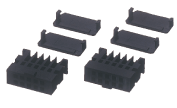
A dedicated crimping tool for Molex connectors (equivalent to Molex part number 57189-5000) is required for wiring. - For the MIL connector type, press-fit sockets for wire-pressed terminal cable and contacts are included.
A multi-wire connector pressure contact tool (part number AXY52000FP) is required for wiring.
Others
- FP7 CPU units
Data collected by the FP7 can be displayed in a web browser.
FP7 equips Web server function and E-mail sending function.
Option
Programming tools
For software specifications, please refer to the web page of each software.
>> Refer to "Control FPWIN GR7"
>> Refer to "Control FPWIN Pro7"
| Product name | Type | Part No. | ||
|---|---|---|---|---|
| Programming software for Windows® Control FPWIN GR7 | Japanese version | FP7 series: Supports only CPU without encryption function | AFPSGR7JP | |
| Security enhanced type | FP7 series: Supports both CPU with / without encryption function | AFPSGR7JPS | ||
| English version | FP7 series: Supports only CPU without encryption function | AFPSGR7EN | ||
| Security enhanced type | FP7 series: Supports both CPU with / without encryption function | AFPSGR7ENS | ||
| Programming software for Windows® Control FPWIN Pro7 | Japanese English Chinese Korean | Supports all FP series PLCs (FP7 series: Supports only CPU without encryption function) | AFPSPR7A | |
| Supports all FP series PLCs (FP7 series: Supports both CPU with / without encryption function) * The encryption function will be offered in the future. | AFPSPR7AS | |||
* Windows is trademarks or registered trademarks of Microsoft Corporation in the United States and other countries.
* For other details on older PLCs, etc., please refer to the pages of each software.
Wiring tools
| Multi-wire connector pressure contact tool Necessary when wiring transistor output type MIL connectors. | AXY52000FP |

Parts for mounting
| Slim 30 type mounting plate Screw-stop attachment plate. 30 mm 1.181 inch width type | AFP0811 (set of 10) |
| Slim type mounting plate Screw-stop attachment plate. Slim model. | AFP0803 (set of 10) |
| Flat type mounting plate Screw-stop attachment plate. Flat model. | AFP0804 (set of 10) |
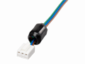
I/O cables
| Transistor output type I/O Loose-wiring cable (10 leads) with MIL connectors attached at one end, AWG22, 0.3 mm2, 1 set: 2 cables (blue & white). | Length: 1 m 3.281 ft. (2 cable set) | AFP0521 |
| Length: 3 m 9.843 ft. (2 cable set) | AFP0523 |
*1
One I/O cable set (2 cables) is necessary with the following models: C16T / E16X, E16T / E16YT
*2
Two I/O cable sets (total 4 cables) are necessary with the following models: C32T / E32T
Maintenance parts
| Push-in terminal socket Attaches to push-in terminal block types. | AFP0809 (2 sockets per pack) |
| Screw terminal socket Attaches to terminal screw block types. | AFP0802 (2 sockets per pack) |
| Molex socket Attaches to Molex connector types. | AFP0801 (2 sockets per pack) |
| Wire-press socket Attaches to MIL connector output type. Contact (AWG #22, #24) included | AFP0807 (2 sockets per pack) |
| Power cable Attaches to FP0R control unit and analog output unit.(Length: 1 m 3.28 ft) | AFPG805 (1 cable per pack) |
| Power cable Attaches to FP0R Expansion units (relay output) and FP0 CC-Link slave unit.(Length: 1 m 3.28 ft) | AFP0581 (1 cable per pack) |
Pressure contact for multi-wire
| Product name | Part No. | Specications |
|---|---|---|
| Pressure contact for multi-wire | AXW7221FP (5 pins per 1 series) | AWG22 or AWG24, outer diameter of coating ø1.5 to 1.1, stranded wire * AWG22 is a 12/0.18 stranded wire. |
| AXW7231FP (5 pins per 1 series) | AWG26 or AWG28, outer diameter of coating ø1.3 to 1.1, stranded wire |
RT-3 unit relays (Power PhotoMOS relay type)
| Contact arrangement | Type | Rated input voltage | RT-3 Unit relay | ||
|---|---|---|---|---|---|
| Product No. | Part No. | Packing quantity | |||
| 1 Form A x 4 | DC only (equipped with AQZ102) | 12 V DC | RT3SP1-12V | AY34001 | Inner carton: 1 piece Outer case: 20 pieces |
| 24 V DC | RT3SP1-24V | AY34002 | |||
| AC / DC dual use (equipped with AQZ204) | 12 V DC | RT3SP2-12V | AY35001 | ||
| 24 V DC | RT3SP2-24V | AY35002 | |||
Notes 1:
Only for use with Power PhotoMOS relays. Cannot be equipped with PA relays.
Notes 2:
Please consult us other contact arrangement.
4-point terminals
| Type | Rated input voltage | Part No. |
|---|---|---|
| PA relay and Voltage sensitive type power PhotoMOS relay type | 12, 24 V DC | AY30000 |
Power PhotoMOS relay
(voltage sensitive type)

Mountable relays for 4-point terminal
| Product name | Part No. |
|---|---|
| Power PhotoMOS relay (voltage sensitive type) | AQZ10*D (DC only) |
| AQZ20*D (AC / DC dual use) |
Note :
Never mount relays into this product other than those given above.
Doing so will cause malfunction, breakdown, and breakdown of the connected product.
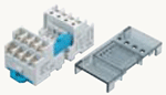
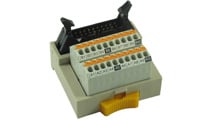
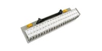
WAGO DIO Station
For Easy and Secure Connection Between FP0R and a Sensor
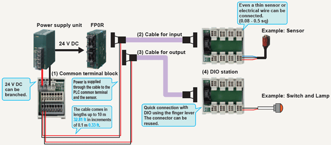
(2)(3) Cable specifications
AWG28, Rated voltage: 30 V
Outer diameter of sheath: φ 4.4 φ 0.17
Minimum allowable bending radius: R = 13.2
Power supply wire: 0.3 sq, 250 mm 9.84 in

| Product name | Product number | Ident number |
|---|---|---|
| (1) Common terminal block | PM-PW8-739/3.5 | 51197832 |
| (2) PM flexible cable for input | PM-FP0X-M733SS-F1M | 51251907 |
| (3) PM flexible cable for output | PM-FP0Y-M733SS-F1M | 51251909 |
| (4) 8 ponts, MIL-DIO station | PM-M733-3X8PC-S1 | 51238076 |
| Contact WAGO Kontakttechnik GmbH & Co. KG for inquiries about DIO Station. URL : https://www.wago.com/global/
|
Connector terminals
Connector terminals recommended for use with the FP0R
TOYOGIKEN CO., LTD.
Connector terminal parts numbers
・PCX-1H20 (angled, spring-lock type, poles: 20P)
・PCN7-1H20 (crimping terminal type, poles: 20P)
Cable parts numbers
・Cable for connection to Panasonic Industry FP0R (custom-made)
SA14083-01-*M (Terminal Side 20P⇔PLC side 10Px2, unshielded)
*Cable length (m ft): 0.5 1.640 / 1 3.281 / 1.5 4.921 / 2 6.562 / 3 9.843
| To learn more about connector terminals, please contact TOYOGIKEN CO., LTD. URL:https://www.togi.co.jp/en/ |
Specifications
- Performance specifications (FP0R Control units)
- General specifications (FP0R Control units)
- Input specifications (Common to control units and expansion units)
- Output specifications (Common to control units and expansion units)
- I/O circuit diagrams
- Analog unit specifications
- Thermocouple unit specifications (FP0 Expansion units)
- I/O Link unit specifications (FP0 Expansion units) [Discontinued products]
- FP Web-server2 unit specifications (FP0 Expansion units) [Discontinued products]
- CC-Link slave unit specifications (FP0 Expansion units)
- Power supply unit specifications (FP0 Expansion units)
- Current consumption
Performance specifications (FP0R Control units)
| Product type of FP0R control unit | FP0R-C10 (Relay output type only) | FP0R-C14 (Relay output type only) | FP0R-C16 (Transistor output type only) | ||
|---|---|---|---|---|---|
| Programming method / Control method | Relay symbol / Cyclic operation | ||||
| Number of I/O points | No expansion (Control unit only) | 10 points [Input: 6, Relay output: 4] | 14 points [Input: 8, Relay output: 6] | 16 points [Input: 8, Transistor output: 8] | |
| With expansion 1 Same type of control and expansion units (Note) | Max. 58 points | Max. 62 points | Max. 112 points | ||
| With expansion 2 Mix type of relay and transistor units (Note) | Max. 106 points | Max. 110 points | Max. 112 points | ||
| Program memory | EEPROM (no backup battery required) | ||||
| Program capacity | 16 k steps | ||||
| Number of instructions | Basic | 110 approx. | |||
| High-level | 210 approx. | ||||
| Operation speed | Up to 3,000 steps | Basic instructions: 0.08 μs min. Timer instructions: 2.2 μs min. High-level instructions: 0.32 μs (MV instruction) Min. | |||
| 3,001st and later steps | Basic instructions: 0.58 μs min. Timer instructions: 3.66 μs min. High-level instructions: 1.62 μs (MV instruction) Min. | ||||
| Operation memory | Relay | Internal relay (R) | 4,096 points | ||
| Timer / Counter (T / C) | 1,024 points | ||||
| Memory area | Data register (DT) | 12,315 words | |||
| Index register (IX, IY) | 14 words (IO to ID) | ||||
| Master control relay points (MCR) | 256 words | ||||
| Number of labels (JMP and LOOP) | 256 labels | ||||
| Differential points | Equivalent to the program capacity | ||||
| Number of step ladder | 1,000 stages | ||||
| Number of subroutines | 500 subroutines | ||||
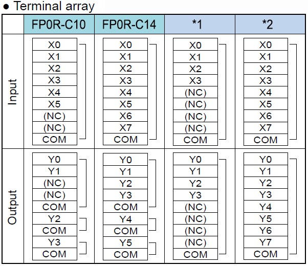
| Special functions | High speed counter (HSC) | Single-phase 6 points (C10: Single-phase 4 points) (50 kHz max. each) or 2-phase 3 points (C10: 2-phase 2 points) (15 kHz max. each) (Note) | |||
| Pulse output | Not available | 4 points (50 kHz max. each) 2 channels can be controlled individually.(Note) | |||
| PWM output | Not available | 4 points (6 Hz to 4.8 kHz) | |||
| Pulse catch input / interrupt input | Total 8 points (with high speed counter) | ||||
| Interrupt program | Input: 8 programs (6 programs for C10 only) / Periodic: 1 program / High speed counter match, Pulse output match: 4 programs | ||||
| Periodical interrupt | In units of 0.5 ms: 0.5 ms to 1.5 sec. / In units of 10 ms: 10 ms to 30 sec. | ||||
| Constant scan | In units of 0.5 ms: 0.5 ms to 600 ms | ||||
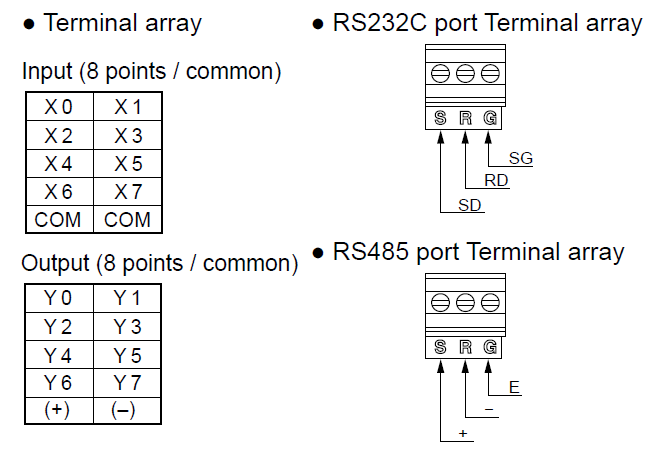
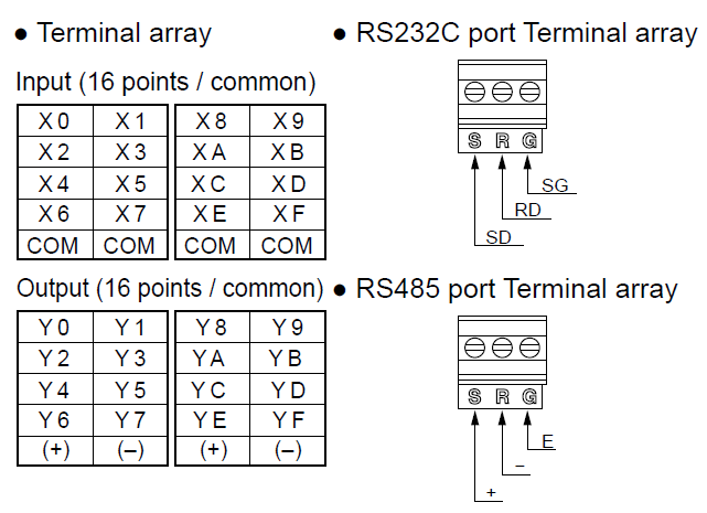
| RS-232C port | One RS-232C port is mounted on each of C10CRS, C10CRM, C14CRS, C14CRM, C16CT, C16CP, C32CT, C32CP, T32CT, T32CP, F32CT and F32CP type (3P terminal block) Transmission speed (Baud rate): 2,400 to 115,200 bits/sec, Transmission distance: 15 m 9.843 ft. Communication method: half duplex | ||||
| RS-485 port | One RS-485 port is mounted on each of C10MRS, C14MRS, C16MT, C16MP, C32MT, C32MP, T32MT, T32MP, F32MT and F32MP type(3P terminal block) Transmission speed (Baud rate): 115.2 kbps (It is possible to change to 19.2 kbps by the setting.), Transmission distance: 1,200 m 3,937 ft, Communication method: half duplex | ||||
| Maintenance | Memory backup | Program and system register | Stored program and system register in EEPROM | ||
| Operation memory | Stored fixed area in EEPROM Counter: 16 points Internal relay: 128 points Data register: 315 words | ||||
| Self-diagnostic function | Watchdog timer (690 ms approx.), Program syntax check | ||||
| Real-time clock function | Not available | ||||
| Other functions | Rewriting in RUN mode (Simultaneous rewriting capacity: 512 steps), Download in RUN mode (All programs), Password function (4-digit, 8-digit), Read protection setting | ||||
| Product type of FP0R control unit | FP0R-C32 (Transistor output type only) | FP0R-T32 (Transistor output type only) | FP0R-F32 (Transistor output type only) | ||
|---|---|---|---|---|---|
| Programming method / Control method | Relay symbol / Cyclic operation | ||||
| Number of I/O points | No expansion (Control unit only) | 32 points [Input: 16, Transistor output: 16] | 32 points [Input: 16, Transistor output: 16] | ||
| With expansion 1 Same type of control and expansion units (Note) | Max. 128 points | Max. 128 points | |||
| With expansion 2 Mix type of relay and transistor units (Note) | Max. 128 points | Max. 128 points | |||
| Program memory | EEPROM (no backup battery required) | ||||
| Program capacity | 32 k steps | ||||
| Number of instructions | Basic | 110 approx. | |||
| High-level | 210 approx. | ||||
| Operation speed | Up to 3,000 steps | Basic instructions: 0.08 μs Min. Timer instructions: 2.2 μs Min. High-level instructions: 0.32 μs (MV instruction) Min. | |||
| 3,001st and later steps | Basic instructions: 0.58 μs Min. Timer instructions: 3.66 μs Min. High-level instructions: 1.62 μs (MV instruction) Min. | ||||
| Operation memory | Relay | Internal relay (R) | 4,096 points | ||
| Timer / Counter (T / C) | 1,024 points | ||||
| Memory area | Data register (DT) | 32,765 words | |||
| Index register (IX, IY) | 14 words (IO to ID) | ||||
| Master control relay points (MCR) | 256 words | ||||
| Number of labels (JMP and LOOP) | 256 labels | ||||
| Differential points | Equivalent to the program capacity | ||||
| Number of step ladder | 1,000 stages | ||||
| Number of subroutines | 500 subroutines | ||||
| Special functions | High speed counter (HSC) | Single-phase 6 points (50 kHz max. each) or 2-phase 3 points (15 kHz max. each) (Note) | |||
| Pulse output | 4 points (50 kHz max. each) 2 channels can be controlled individually.(Note) | ||||
| PWM output | 4 points (6 Hz to 4.8 kHz) | ||||
| Pulse catch input / interrupt input | Total 8 points (with high speed counter) | ||||
| Interrupt program | Input: 8 programs (6 programs for C10 only) / Periodic: 1 program / High speed counter match, Pulse output match: 4 programs | ||||
| Periodical interrupt | In units of 0.5 ms: 0.5 ms to 1.5 sec. / In units of 10 ms: 10 ms to 30 sec. | ||||
| Constant scan | In units of 0.5 ms: 0.5 ms to 600 ms | ||||
| RS-232C port | One RS-232C port is mounted on each of C10CRS, C10CRM, C14CRS, C14CRM, C16CT, C16CP, C32CT, C32CP, T32CT, T32CP, F32CT and F32CP type (3P terminal block) Transmission speed (Baud rate): 2,400 to 115,200 bits/sec, Transmission distance: 15 m 9.843 ft. Communication method: half duplex | ||||
| RS-485 port | One RS-485 port is mounted on each of C10MRS, C14MRS, C16MT, C16MP, C32MT, C32MP, T32MT, T32MP, F32MT and F32MP type(3P terminal block) Transmission speed (Baud rate): 115.2 kbps (It is possible to change to 19.2 kbps by the setting.), Transmission distance: 1,200 m 3,937 ft, Communication method: half duplex | ||||
| Maintenance | Memory backup | Program and system register | Stored program and system register in EEPROM | ||
| Operation memory | Stored fixed area in EEPROM Counter: 16 points Internal relay: 128 points Data register: 315 words | Backup of the entire area by FeRAM (without the need for a battery) | |||
| Backup of the entire area by a built-in secondary battery | |||||
| Self-diagnostic function | Watchdog timer (690 ms approx.), Program syntax check | ||||
| Real-time clock function | Not available | Available | Not available | ||
| Other functions | Rewriting in RUN mode (Simultaneous rewriting capacity: 512 steps), Download in RUN mode (All programs), Password function (4-digit, 8-digit), Read protection setting | ||||
Note: For the limitations while operating units, reter to the manual.
General specifications (FP0R Control units)
| Item | Specifications | |
|---|---|---|
| Rated voltage | 24 V DC | |
| Operating voltage range | 20.4 to 28.8 V DC | |
| Allowed momentary power off time | C10, C14, C16 | 5 ms (at 20.4 V DC), 10 ms (21.6 V DC or higher) |
| C32, T32, F32 | 10 ms (20.4 V DC or higher) | |
| Ambient temperature | 0 to +55 ℃ 32 to +131 ℉ | |
| Storage temperature | -40 to +70 ℃ -40 to +158 ℉ (-20 ℃ to +70 ℃ -4 to +158 ℉ for T32 only) | |
| Ambient humidity | 10 to 95% RH (at 25 ℃ 77 ℉, no condensation) | |
| Storage humidity | 10 to 95% RH (at 25 ℃ 77 ℉, no condensation) | |
| Breakdown voltage (Detection current: 5 mA) | Input terminals - output terminals, Output terminals – power and functional ground terminals --- Transistor output: 500 V AC for 1 minute (Relay output: 1,500 V AC for 1 minute) / Input terminals – power and functional ground terminals, Functional ground terminal – power terminal --- Transistor output: 500 V AC for 1 minute (Relay output: 500 V AC for 1 minute) / Output terminals – output terminals (different common terminals) --- Relay output: 1,500 V AC for 1 minute | |
| Insulation resistance (Test voltage: 500 V DC) | Input terminals - output terminals, input terminals – power and functional ground terminals, output terminals – power and functional ground terminals, functional ground terminal – power terminal --- Transistor output: 100 MΩ minimum (relay output: 100 MΩ minimum) / Output terminals – output terminals (different common terminals) --- Relay output: 100 MΩ minimum | |
| Vibration resistance | 5 to 9 Hz, single amplitude of 3.5 mm, 1 sweep/min; 9 to 150 Hz, constant acceleration of 9.8 m/s2, 1 sweep/min; for 10 min each in X, Y, and Z directions | |
| Shock resistance | 147 m/s2 or more , 4 times each in X, Y, and Z directions | |
| Noise immunity | 1,000 V (p-p) with pulse widths 50 ns and 1 μs (using a noise simulator) (Power supply terminal) | |
| Operating condition | Free from corrosive gasses and excessive dust | |
Input specifications (Common to control units and expansion units)
(As for the limitation on the number of simultaneous ON points, please refer to the manual.)
| Item | Specifications | ||
|---|---|---|---|
| Control unit | Expansion unit | ||
| Rated input voltage | 24 V DC | ||
| Operating voltage range | 21.6 to 26.4 V DC | ||
| Rated input current | 2.6 mA approx. (at 24 V DC) | 4.7 mA approx. (at 24 V DC) | |
| Input impedance | 9.1 kΩ approx. | 5.1 kΩ approx. | |
| Input points per common | 6 points / common (C10), 8 points / common (C14, C16), 16 points / common (C32, T32, F32) | ||
| Min. ON voltage/ON current | 19.2 V / 2 mA | ||
| Max. OFF voltage/OFF current | 2.4 V / 1.2 mA | ||
| Response time | OFF → ON | 20 μs or less * An input time constant (0.1 to 64 ms) can be set. | 2 ms or less |
| ON → OFF | Same as above | Same as above | |
| Insulation method | Photocoupler | ||
* Since the response time of X0 to X7 is very fast (for high-speed counter input) the FP0 happens to chattering noise as an input signal. To prevent this, it is recommended that the timer should be put in the ladder program.
Output specifications (Common to control units and expansion units)
As for the limitation on the number of simultaneous ON points, please refer to the manual.
1. Relay output type
| Item | Specifications | |
|---|---|---|
| Output type | 1a | |
| Rated control capacity | 2 A 250 V AC, 2 A 30 V DC (4.5 A / common) | |
| Response time | OFF → ON | 10 ms approx. |
| ON → OFF | 8 ms approx. | |
| Life time | Mechanical | 2 x 10⁷ operations or more |
| Electrical | 105 operations or more | |
| Surge absorber | None | |
| Output points per common | 2 points / common + 1 point / common + 1point / comon (C10), 4 points / common + 1 point / common + 1point / comon (C14) | |
2. Transistor output type
| Item | Specifications | ||
|---|---|---|---|
| NPN | PNP | ||
| Output type | Open collector | ||
| Rated load voltage | 5 to 24 V DC | 24 V DC | |
| Load voltage allowable range | 4.75 to 26.4 V DC | 21.6 to 26.4 V DC | |
| Max. load current | C16, C32, T32 and F32: 0.2 A / point (Max. 1A per common terminal) E16, E32, E8Y and E16Y: 0.3 A / point (Max. 1A per common terminal) | ||
| OFF state leakage current | 1 μA or less (Note 2) | ||
| ON state voltage drop | 0.2 V DC or less (Note 3) | ||
| Response time | OFF → ON | 20 μs or less (Load current: 5 mA or more), 0.1 ms or less (Load current: 0.5 mA or more) (Note) | |
| ON → OFF | 40 μs or less (Load current: 5 mA or more), 0.2 ms or less (Load current: 0.5 mA or more) (Note) | ||
| External power supply | Voltage | 21.6 to 26.4 V DC | |
| Current | C16, E16T and E8YT: 30 mA or less | C16, E16P and E8YP: 35 mA or less | |
| C32, T32, F32, E32T and E16Y : 60 mA or less | C32, T32, F32, E32P and E16YP : 70 mA or less | ||
| Surge absorber | Zener diode | ||
| Output points per common | 8 points / common (C16T), 16 points / common (C32, T32, F32) | ||
| Insulation method | Photocoupler | ||
Notes:
1) For expansion unit: 1 ms or less
2) For expansion unit: 100 μA or less
3) For expansion unit: 1.5V or less
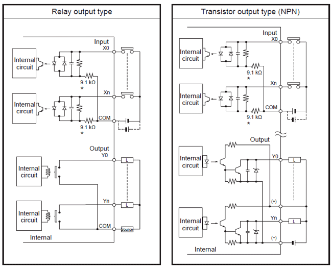
I/O circuit diagrams
Analog unit specifications
| Product name | Analog input units | Analog I/O units (Only input section) | ||||
|---|---|---|---|---|---|---|
| Part No. | AFP0RAD4(U) | AFP0RAD8(U) | AFP0RA21(U) | AFP0RA42(U) | ||
| Number of input / output channels | 4 / 0 | 8 / 0 | 2 / 1 | 4 / 2 | ||
| Input range (digital input range) | Voltage | -10 to +10 V 14 bits (-8,000 to +8,000) -5 to +5 V 14 bits (-8,000 to +8,000) 0 to +10 V 14 bits (0 to +16,000) 0 to +5 V 14 bits (0 to +16,000) | ||||
| -100 to +100 mV 12 bits (-2,000 to +2,000)(Note) | - | |||||
| Current | 0 to 20 mA 14 bits (0 to +16,000) | |||||
| Absolute maximum input | Voltage | ±15 V | ||||
| Current | ±30 mA | |||||
| Input impedance | Voltage | 1 MΩ approx. | ||||
| Current | 250 Ω approx. | |||||
| Max. resolution | 14 bits (1/16,000) | |||||
| Overall accuracy | Voltage | ± 100mV | ±0.6 % F.S. or less (at +25 ℃ +77 ℉) ±1.0 % F.S. or less (at 0 to +55 ℃ +32 to +131 ℉) | - | ||
| Others | ±0.2 % F.S. or less (at +25 ℃ +77 ℉) ±0.4 % F.S. or less (at 0 to +55 ℃ +32 to +131 ℉) | |||||
| Current | ±0.3 % F.S. or less (at +25 ℃ +77 ℉) ±0.6 % F.S. or less (at 0 to +55 ℃ +32 to +131 ℉) | |||||
| Conversion speed | 2 ms/all channels | |||||
| Other functions | Averaging processing (moving, number of times) Compatibility function for existing programs (12 bits) | |||||
| Insulation method | Between input terminals and internal circuit | Photocoupler and isolated DC/DC converter | ||||
| Between channels | Not insulated | |||||
(Note): It is equipped in the products after Ver.1.2 (12-bit mode only)
| Product name | Analog output unit | Analog I/O units (Only output section) | ||
|---|---|---|---|---|
| Part No. | AFP0RDA4(U) | AFP0RA21(U) | AFP0RA42(U) | |
| Number of input / output channels | 0 / 4 | 2 / 1 | 4 / 2 | |
| Output range (analog output setting range) | Voltage | -10 to +10 V 14 bits (-8,000 to +8,000) -5 to +5 V 14 bits (-8,000 to +8,000) 0 to +10 V 14 bits (0 to +16,000) 0 to +5 V 14 bits (0 to +16,000) | ||
| Current | 0 to 20mA 14 bits (0 to +16,000) 4 to 20mA 14 bits (0 to +16,000) | |||
| Output impedance | Voltage | 0.5 Ω or less | ||
| Max. output current | Voltage | ±10 mA | ||
| Permissible output load resistance | Current | 500 Ω or less | ||
| Max. resolution | 14 bits (1/16,000) | |||
| Overall accuracy | Voltage | ±0.2 % F.S. or less (at +25 ℃ +77 ℉) ±0.4 % F.S. or less (at 0 to +55 ℃ +32 to +131 ℉) | ||
| Current | ±0.3 % F.S. or less (at +25 ℃ +77 ℉) ±0.6 % F.S. or less (at 0 to +55 ℃ +32 to +131 ℉) | |||
| Conversion speed | 500 μs/all channels | |||
| Other functions | Compatibility function for existing programs (12 bits) | |||
| Insulation method | Between the output terminals and internal circuit | Photocoupler and isolated DC/DC converter | ||
| Between channels | Not insulated | |||
Discontinued products
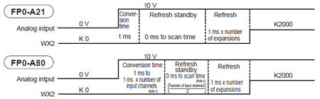
| Item | Analog input specifications | ||
|---|---|---|---|
| FP0-A21 | FP0-A80 | ||
| Number of input points | 2 channels / unit | 8 channels /unit Number of input points can be changed 2, 4, 6 and 8 channels. | |
| Input range | Voltage range | 0 to 5 V (K0 to K4000) (Note 1)/ -10 to +10 V (K -2000 to K +2000) (Note 1) | 0 to 5 V (K0 to K4000) (Note 1)/ -10 to +10 V -100 to +100 mV (K -2000 to K +2000) (Note 1) |
| Current range | 0 to 20 mA (K 0 to K 4000) (Note 1) | ||
| Resolution | 1/4,000 (12 bits) | ||
| Conversion speed | 1 ms / channel (Note 2) | ||
| Overall precision | ±1 % FS or less (0 to 55 ℃ 32 to 131 ℉), ±0.6 % F.S or less (25 ℃ 77 ℉) | ||
| Input impedance | Voltage range | 1 MΩ or more | |
| Current range | 250 Ω | ||
| Absolute maximum input | Voltage range | ±15 V | |
| Current range | ±30 mA | ||
| Insulation method | Between analog input terminal and FP0 internal circuit: optical coupler insulation (non-insulated between channels) Between analog input terminal and analog I/O unit external power supply: based on insulation type DC/DC converter Between analog input terminal and analog output terminal: based on insulation type DC/DC converter | Between analog output terminal and FP0 internal circuit: optical coupler insulation (non-insulated between channels) Between analog input terminal and A/D converter unit external power supply: based on insulation-type DC/DC converter | |
| Number of I/O contact points | 32 input contact points | ||
| Averaging function | None | Can be switched on and off. | |
Notes:
1) If the analog input value exceeds the upper or lower limit, the digital value will preserve the upper or lower limit.
2) The time shown below is required before the analog data is reflected in the control unit input.
3) Settings value switch for the number of input channel
4) With each one scan of the control unit, the data for two channels will be loaded into control unit. In other words, if the input channel number switch is set to 8-channel, the data in the control unit will be updated once every four scans.
Discontinued products
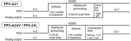
| Item | Analog output specifications | |||
|---|---|---|---|---|
| FP0-A21 | FP0-A04V | FP0-A04I | ||
| Number of input points | 1 channel / unit | Voltage output 4 channels / units | Current output 4 channels / units | |
| Output range | Voltage range | -10 to +10 V range (K -2000 to K +2000) (Note 1) | - | |
| Current range | 0 to 20 mA (K0 to K4000) (Note 1) | - | 4 to 20 mA (K0 to K4000) (Note 1) | |
| Resolution | 1/4,000 (12 bits) | |||
| Conversion speed | 500 μs / channel (Note 2) | |||
| Overall precision | ±1 % FS or less (0 to 55 ℃ 32 to 131 ℉), ±0.6 % F.S or less (25 ℃ 77 ℉) | |||
| Output impedance | Voltage range | 0.5 Ω or less | - | |
| Max. output current | Voltage range | ±10 mA | - | |
| Absolute output load resistance | Current range | 30 Ω or less | 1,000 Ω or less | 500 Ω or less |
| Insulation method (Note 2) | Between analog output terminal and FP0 internal circuit: optical coupler insulation (non-insulated between channels) Between analog output terminal and analog I/O unit extenal power supply: based on insulation type DC/DC converter Between analog output terminal and analog input terminal: based on insulation type DC/DC converter | Between analog output terminal and FP0 internal circuit: optical coupler insulation (non-insulated between channels) Between analog output terminal and D/A converter unit external power supply: based on insulation type DC/DC converter | ||
| Number of I/O contact points | 16 output contact points | 16 input contact points, 32 output contact points (Note 3) | ||
Notes:
1) If the digital value exceeds the upper or lower limit, D/A conversion will not take place.
(Analog output will remain as the previous data.)
2) The time shown below is required to update the actual analog output.
3) The data for two channels will be output to the D/A converter unit with one scan of the control unit.
Thermocouple unit specifications (FP0 Expansion units)
| Item | Specifications |
|---|---|
| Number of input points | 4-channel, 8-channel (The number of input points can be changed 2, 4, 6 and 8 channels.) |
| Input range | Range for K and J -100.0 to 500.0 ℃/-148.0 to 790.0 ℉ (Note 1)(Note 7) |
| Range for T -100.0 to 400.0 ℃/-148.0 to 752.0 ℉(Note 7) | |
| Range for R 0 to 1500.0 ℃/32.0 to 1590.0 ℉ (Note 1) | |
| Digital output | K and J (when using ℃): K -1000 to K5000 K and J (when using ℉): K -1480 to K7900 (Note 1) (When range over using ℃: K-1001, K5001 or K8000) (When range over using ℉: K-1481, K7901 or K8000) (When the thermocouple broken: K8000) (Note 2) (Until the temperature can be measured at the initial startup: K8001) (Note 3) T (when using ℃): K -1000 to K4000 T (when using ℉): K -1480 to K7520 (When range over using ℃: K -1001, K4001 or K8000) (When range over using ℉: K -1481, K7521 or K8000) (When the thermocouple broken: K8000) (Note 2) (Until the temperature can be measured at the initial startup: K8001) (Note 3) R (when using ℃): K0 to K15000 R (when using ℉): K320 to K15900 (Note 1) (When range over using ℃: K 0, K15001 or K16000) (When range over using ℉: K 0, K15901 or K16000) (When the thermocouple broken: K16000) (Note 2) (Until the temperature can be measured at the initial startup: K16001) (Note 3) |
| Resolution | 0.1 ℃ |
| Sampling cycle (Note 5) | 300 ms: when using 2 channels for an input points (Note 4) 500 ms: when using 4 channels for an input points (Note 4) 700 ms: when using 6 channels for an input points (Note 4) 900 ms: when using 8 channels for an input points (Note 4) |
| Indication accuracy (Note 7) | Range for K, J and T ±0.2 % F.S. (at +25 ℃ +77 °F) ±0.4 % F.S. (at 0 to +55 ℃ +32 to +131 °F) Range for R ±0.2 % F.S. (at +25 ℃ +77 °F) ±0.4 % F.S. (at 0 to +55 ℃ +32 to +131 °F) |
| Reference junction compensation accuracy | ±1.0 ℃ |
| Input impedance | 1 MΩ or more |
| Insulation method |
|
| Number of I/O contact points | 32 input contact points (Note 6) |
Notes:
1) The measurement range available for degree Celsius is not available for degree Fahrenheit, of which the upper-limit measurement is set lower than degree Celsius, since the digital value (temperature value displayed) for degree Fahrenheit is bigger than that for degree Celsius.
2) When the thermocouple is broken, the digital value will become K8000 or K16000 within 70 seconds since broken. Practice in the ladder program a process for avoiding a risk, would be resulting from a broken thermocouple, and exchange the thermocouple.
3) Until the conversion data will be ready after the initial startup was made, the digital value shows K8001 or K16001. Those are not a temperature data. Create a ladder program, so that they are not acquired as a temperature data.
4) The settings of the input channel selection switch.
5) Conversion values for 6-time measurements (6 from the latest 8 measurements, excluding the max. and min.) are averaged, so that it takes time for the digital value to be displayed due to the rapid temperature change.
6) The control unit reads the data for 2 channels per 1 scan by the control unit. Read data by utilizing the sample program given in the product specifications and manual.
7) If the measurement temperature is below -50 ℃/-58 ℉, temperature measurement is possible, but accuracy cannot be guaranteed.
I/O Link unit specifications (FP0 Expansion units) [Discontinued products]
| Item | Specifications |
|---|---|
| Communication method | Two-wire, half duple |
| Synchronous method | Asynchronous method |
| Transmission line | 2-wire cable (Twisted-pair cable or VCTF 0.75 mm2 x 2C equivalent) |
| Transmission distance (Total distance) | Max. 700 m 2,297 ft (using twisted-pair cable) Max. 400 m 1,312 ft (using VCTF cable) |
| Transmission speed (Baud rate) | 0.5 Mbits/s |
| Number of control I/O point per an I/O link unit | 64 points (Input: 32 points and Output: 32 points) (Note) |
| Remote I/O map allocation | 32X / 32Y |
| Interface | Conforming to RS485 |
| Transmission error check | CRC (Cyclic Redumdancy Check) method |
Note: This point number is the number of points that can be linked for inputting and outputting via the host PLC and network MEWNET-F. If the output for the I/O link unit error flag is set to ON, this number becomes 63 points (31 input points and 32 output points).
FP Web-server2 unit specifications (FP0 Expansion units) [Discontinued products]
| Item | Specifications |
|---|---|
| Communication functions | RS232C Ethernet conversion (PLC remote programming via Ethernet) E-mail sending function HTTP server function General-purpose communication (Server/Client) PPP server function |
| Communication interface | RS232C terminal block 3-pin: Mainly used for PLC connection RS232C D-Sub 9-pin: Mainly used for Modem connection 100 BASE-TX (RJ45): Used for Ethernet connection |
| RS232C communication | Transmission speed: 1,200, 2,400, 4,800, 9,600, 19,200, 38,400, 57,600, 115,200 bits/s Data length: 7 bits / 8 bits, Parity: Even / Odd / None |
| Ethernet communication | 100 Mbits/s (100 BASE-TX: RJ45) |
| Supported protocol | TCP, UDP, IP, DHCP, FTP, TELNET, HTTP, SMTP, and PPP |
| Memory size | 148 kB approx. (for storing htm files) |
| Setup method | Setup using FP Web Configurator Tool 2 |
CC-Link slave unit specifications (FP0 Expansion units)
| Item | Communication specifications | ||
|---|---|---|---|
| Version | CC-Link Ver.1.10 | ||
| Communication method | Broadcast polling method | ||
| Transmission speed | 10 Mbits/s, 5 Mbits/s, 2.5 Mbits/s, 625 kbits/s, 156 kbits/s | ||
| Max. transmission distance (Note) | Ver.1.10 CC-Link cable CC-Link high-performace cable | CC-Link cable | |
| 10 Mbits/s | 100 m 328 ft | 100 m 328 ft | |
| 5 Mbits/s | 160 m 525 ft | 150 m 492 ft | |
| 2.5 Mbits/s | 400 m 1,312 ft | 200 m 656 ft | |
| 625 kbits/s | 900 m 2,952 ft | 600 m 1,969 ft | |
| 1,200 m 3,937 ft | 1,200 m 3,937 ft | ||
| Interface | RS-485 | ||
| Station type | Remote device station | ||
| Number of occupied stations | 1 station | ||
Note : Length of the multi-drop connected cables at both ends. The cable length has restrictions in communication speed, CC-Link version, and dedicated cables to be used.
For details concerning the CC-Link, refer to the CC-Link Partner Association.
When an FP0 thermocouple unit is used with an FP0 CC-Link slave unit, the measurement accuracy of the thermocouple unit which is installed on the left of the CC-Link slave unit is as shown in the table below.
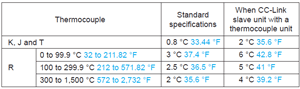
Power supply unit specifications (FP0 Expansion units) [Discontinued products]
| Item | Specifications | |
|---|---|---|
| Input | Rated input voltage | 100 to 240 V AC |
| Variable input voltage range | 85 to 264 V AC | |
| Rated frequency | 50/60 Hz | |
| Frequency range | 47 to 63 Hz | |
| Number of phases | Single-phase | |
| Inrush current | 30 A (0 to P) or less, with cold start | |
| Leakage current | 0.75 mA or less | |
| Allow able momentary power off time | 10 ms or more | |
| Output | Rated voltage | 24 V DC |
| Voltage accuracy | ±5 % | |
| Rated current | 0.7 A (Note) | |
| Output current range | 0 to 0.6 A | |
| Ripple voltage | 500 mV or less | |
| Protective functions | Over-current protection | 0.63 A or more |
| Over-voltage protection | Available | |
Note: Start up may not be possible if a device with a large inrush current is connected even if below the rated current. In such a case, we recommend suppressing the inrush current by inserting a 1 to 2 Ω resister between the power supply unit and the device.
Applicable crimp teriminals
| Manufacturer | Part number | Applicable wiring |
|---|---|---|
| JST Mfg. Co., Ltd. | V1.25-M3 (round type) V1.25-S3A (fork type) | 0.35 to 1.65 mm2AWG #22 to #15 |
| V2-M3 (round type) V2-S3A (fork type) | 1.04 to 2.00 mm2AWG #17 to #14 |
Current consumption
| Type of unit | Control unit current consumption (24 V DC) | Expansion unit current consumption (24 V DC) | |
|---|---|---|---|
| FP0R control units | C10 | 100 mA or less | - |
| C14 | 120 mA or less | - | |
| C16 | 70 mA or less | - | |
| C32 T32 F32 | 90 mA or less | - | |
| FP0R expansion units | AFP0RE8X | 10 mA or less | - |
| AFP0RE8R | 10 mA or less | 50 mA or less | |
| AFP0RE8YR | 10 mA or less | 100 mA or less | |
| AFP0RE8YT/P | 15 mA or less | - | |
| AFP0RE16X | 10 mA or less | - | |
| AFP0RE16R | 20 mA or less | 100 mA or less | |
| AFP0RE16T/P | 20 mA or less | - | |
| AFP0RE16YT/P | 25 mA or less | - | |
| AFP0RE32T/P | 35 mA or less | - | |
| FP0R intelligent units | AFP0RAD4 | 45mA or less | - |
| AFP0RAD8 | 45mA or less | - | |
| AFP0RDA4 | 10mA or less | 180mA or less | |
| AFP0RA21 | 10mA or less | 80mA or less | |
| AFP0RA42 | 10mA or less | 120mA or less | |
| FP0 intelligent units | FP0-A21 | 20 mA or less | 100 mA or less |
| FP0-A80 | 20 mA or less | 60 mA or less | |
| FP0-A04V | 20 mA or less | 100 mA or less | |
| FP0-A04I | 20 mA or less | 130 mA or less | |
| FP0-TC4 FP0-TC8 | 25 mA or less | - | |
| Communication units | FP0-CCLS | 40 mA or less | 40 mA or less |
| FP0-IOL | 30 mA or less | 40 mA or less | |
| FP-WEB2 | - | 95 mA or less (at 24 V DC) 240 mA or less (at 12 V DC) | |
| AFP15402 (C-NET adapter) | 50 mA or less | - | |
Notes:
1) Control unit current consumption
This refers to the current consumed via the power supply connector of the control unit. If expansion units or intelligent units are added, the current is increased by the value indicated above.
2) Expansion unit current consumption
This refers to the current consumed via the power supply connector of the expansion unit.
Units with no value indication don't have a power supply connector.
3) Refer to Input specifications and Output specifications for current consumption of power supply connected to input terminal and output terminal.
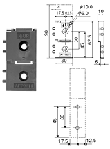
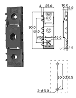
Dimensions
- Unit: mm in
*The illustrations are shown representative product type.Please refer the outside dimensions only.
- FP0R Control units and Expansion units
- FP0R/FP0 Intelligent units
- FP0 Link and communication units
- FP0 Power Supply Unit
FP0R Control units and Expansion units
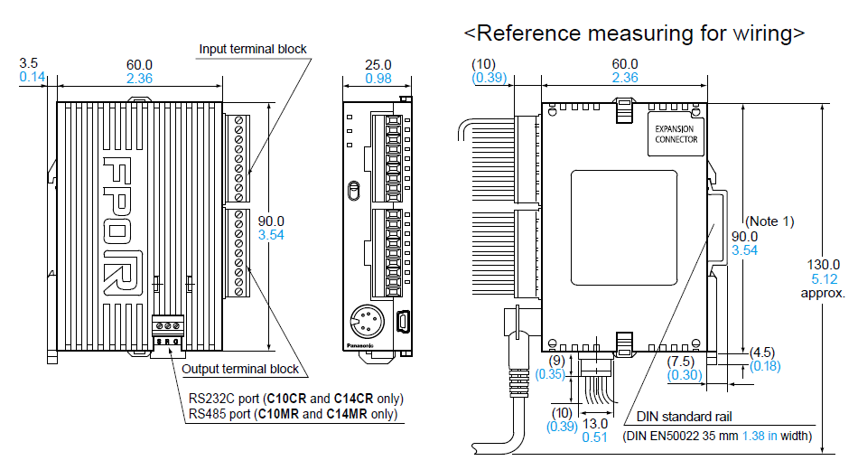
Types of control units
[FP0R-C10/FP0R-C14]
Expansion units
[E8RU/E8RS/E8RM/E8YRU/E8YRS/E16RU/E16RS/E16RM]
Notes:
1) DIN rail is attached on the center of the unit.
2) The AFP0RE8YRS and AFP0RE8YRS are not equipped with an input terminal block.
* The following dimensional diagram shows the control unit screw terminal block type as a representative.
*1 : E8-RU/E8-RS/E8-RM
*2 : E16RU/E16-RS/E16RM/E8-YRU/E8-YRS
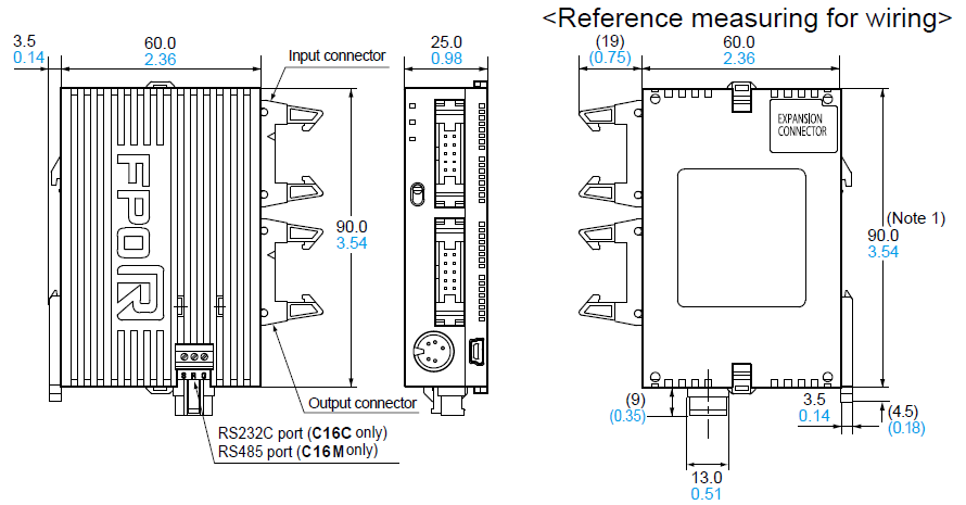
Types of control units
[FP0R-C16]
Expansion units
[E16T/E16P/E8X/E8YT/E8YP]
Notes:
1)DIN rail is attached on the center of the unit.
2) The AFP0RE8X has no output connector.
3) The AFP0RE8YT and AFP0RE8YP has no input connector.
* The following dimensional diagram shows the control unit as a representative.
Note: Two COM terminals on the input circuit are connected inside the unit.
Types of control units
[FP0R-C32/FP0R-T32/FP0R-F32]
Expansion units
[E32T/E32P/E16X/E16YT/E16YP]
Notes:
1) DIN rail is attached on the center of the unit.
2) The AFP0RE32T, AFP0RE32P, AFP0RE16X, AFP0RE16YT and AFP0RE16YP are 25 mm 0.98 in each.
3) The AFP0RE16X has no output connector.
4) The AFP0RE16YT and AFP0RE16YP has no input connector.
* The following dimensional diagram shows the control unit as a representative.
Notes:
1) Four COM terminals on the input circuit are connected inside the unit.
2) Two (+) terminals and two (-) terminals on the output circuit are connected respectively inside the unit.
External Dimensions During Expansions
FP0R / FP0 Intelligent units
Analog Unit
[AFP0RAD4(U) / AFP0RA21(U)]
![Analog Unit [AFP0RAD4 / AFP0RA21]](https://tp.industry.panasonic.com/hubfs/pid-corp/products/fasys/plc/plc/fp0r/size_figure/images/pic11.jpg)
Analog Unit
[AFP0RAD8(U) / AFP0RDA4(U) / AFP0RA42(U)]
![Analog Unit [AFP0RAD8 / AFP0RDA4 / AFP0RA42]](https://tp.industry.panasonic.com/hubfs/pid-corp/products/fasys/plc/plc/fp0r/size_figure/images/pic12.jpg)
Analog I/O Unit [Discontinued products]
![Analog I/O Unit [Discontinued products]](https://tp.industry.panasonic.com/hubfs/pid-corp/products/fasys/plc/plc/fp0r/size_figure/images/pic13.gif)
A/D Converter Unit [Discontinued products]
![A/D Converter Unit [Discontinued products]](https://tp.industry.panasonic.com/hubfs/pid-corp/products/fasys/plc/plc/fp0r/size_figure/images/pic14.gif)
D/A Converter Unit [Discontinued products]
![D/A Converter Unit [Discontinued products]](https://tp.industry.panasonic.com/hubfs/pid-corp/products/fasys/plc/plc/fp0r/size_figure/images/pic15.gif)
Thermocouple Unit
FP0 Link/Communication Units
I/O Link Unit [Discontinued products]
![I/O Link Unit [Discontinued products]](https://tp.industry.panasonic.com/hubfs/pid-corp/products/fasys/plc/plc/fp0r/size_figure/images/pic17.gif)
CC-Link Slave Unit
FP0 Power Supply Unit
Power Supply Unit [Discontinued products]
![Power Supply Unit [Discontinued products]](https://tp.industry.panasonic.com/hubfs/pid-corp/products/fasys/plc/plc/fp0r/size_figure/images/pic19.gif)