Basic Information

Built-in dual Ethernet ports
Multiple interfaces that connect with various devices


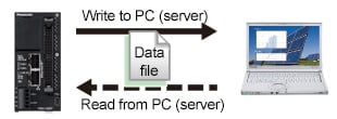
FTP server function (SSL/TLS-compatible)
Allows the PC to read the logging data in the FP0H's SD memory card and to write setting values and other parameters.

FTP client function (SSL/TLS-compatible)
The FP0H can generate and write data files to an FTP server on a PC as well as read data files from the FTP server.
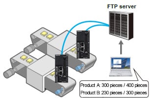
Data collection, data viewing and data writing from multiple units in the form of files
Transfer electric power data from factories and offices to an FTP server on a regular basis.
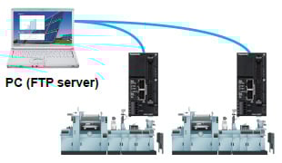
Users can access the accumulating production information in the server at any time.

High-speed operation processing [8 x faster than conventional models!]
Basic instruction: 10 ns to (up to 10 k steps)
High capacity Max. 64 k steps [2 x larger than conventional models!]
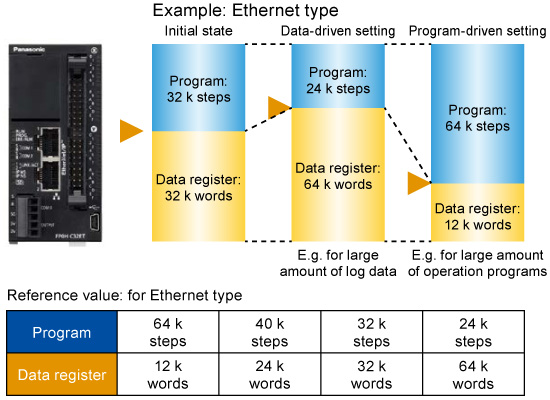
Program capacity: 64 k / 40 k / 32 k / 24 k Step variable
Data capacity: 12 k / 24 k / 32 k / 64 k Step variable

| I/O | 16 input points, 16 output points, Transistor output (NPN / PNP) |
| Built-in I/F | Ethernet × 2 ports, RS232C × 1 channel, USB × 1 channel |
| Expansion I/F | FP0H expansion bus × 1, FP0R expansion bus × 1 Cassette slot × 1 (RS232C, RS232C × 2, RS485, RS232C and RS485) |
| Tool | FPWIN GR7 / FPWIN Pro7 |
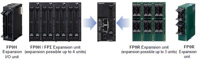
Up to 384 I/O points FP0H / FPΣ / FP0R units can be added.
Can select required functions to control various devices!
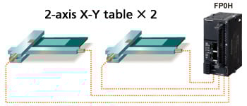
Built-in 4-axis pulse outputs
Built-in 4-axis pulse output, so simultaneous control of 2-axis linear interpolation is possible for two sets. For example, two X-Y tables can be controlled.
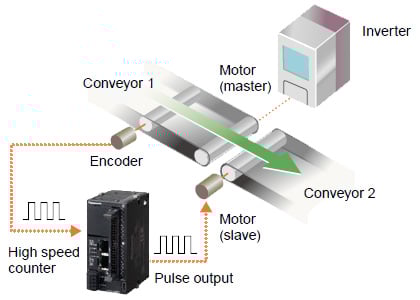
High-speed counter input and pulse output
Ladder programs can be combined to create an application for counting pulse signals from the encoder through the high speed counter input and adjusting the pulse output frequency based on the count to synchronize the slave axis speed with the master axis speed.
In the lower figure, the speed of conveyor 1, which is inverter controlled, is measured based on the encoder pulse count, and pulses are output (for jog operation) to the motor (slave) according to the measured speed in order to synchronize the speed of conveyor 2.
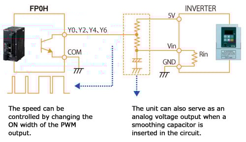
Built-in multipoint PWM outputs (4 channels)
The pulse output port of FP0H can also serve as a PWM output port. One of the application examples is an analog voltage output, which can be used for inverter speed control.

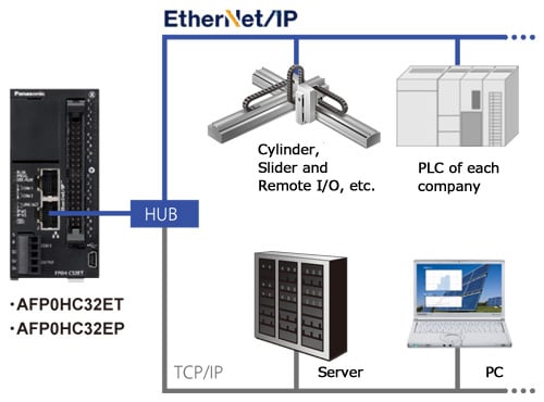
■ EtherNet/IP, Modbus-TCP and MC protocol compatibility*
■ Easy connection with all kinds of robots and PLCs*
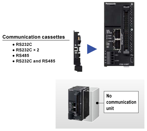
■ Cassette system reduces unit cost and installation space
* Only for Ethernet type
EtherNet/IP compatibility
An Ethernet type control unit supports EtherNet/IP.
Easy connection with all kinds of robots and PLCs enables control and communication.
Note: EtherNet/IP is a trademark of ODVA, Inc.
Cassette system reduces unit cost and installation space
With ease and at low cost, extend the serial communication functionality of control unit.

■ An SD memory card slot and a logging trace function are provided.*
■ A project copy function can copy ladder data without a PC.*
■ Variable data capacity handles capacity shortage.
■ Program capacity: Max. 64 k steps*
* Only for Ethernet type
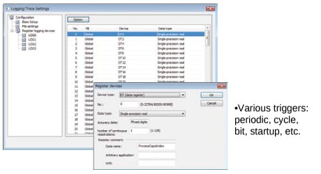
Easy multiple concurrent logging
Logging set up is done via the configuration screen.
Moreover, it is possible to keep up to 4 files concurrently active.
Use program and data register sharing to resolve data space shortage.
No need repurchase expensive upgrade models.
Can update programs with an SD memory card
Can save programs in and read them from an SD memory card.
Programs can be updated easily via an SD memory card.

The control unit controls four axes with pulse output (up to 100 kHz per axis).
You can achieve position control easily only by starting a positioning action pattern configured with a dedicated setting tool.
Positioning control configuration
The positioning table (Note 1) and parameters for each axis (Note 2) are set.
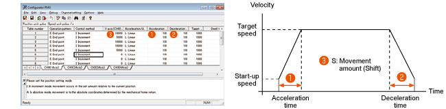
Notes:
1) The positioning table separately shows movement amount, target speed, acceleration and deceleration time, operation mode, and other information for positing control operations.
2) For each axis parameters are shown for limit input logic, deceleration time to stop, and operation conditions for JOG operation and return to point, etc.
The positioning unit (fast start-up in 5 μs) can support ultra-fast linear servos.
Pulse output of up to 4 Mpps and fast start-up in 5 μs can control linear servos.
Ideal for applications that repeat short-stroke actions quickly, such as palletizing of electronics parts
A built-in high speed counter can detect abnormalities.
Counting feedback pulses from encoders during positioning can detect accidents such as the abnormalities in the drive system.
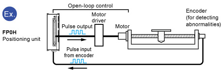
Counts feedback pulses from the encoder to detect abnormalities.
Jog positioning supports fixed feed
Fast start-up and repetitive control can support fixed-feed processing.
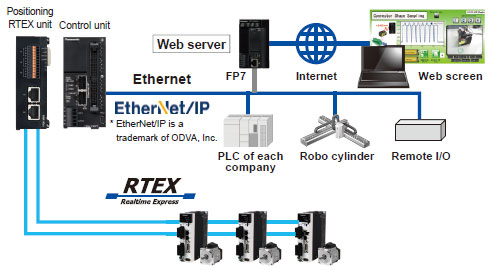
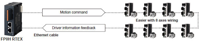
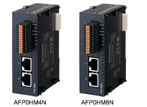
The supported positioning unit RTEX can control Panasonic AC Servo Motors.
 Positioning RTEX units AFP0HM4N(4-axis type) / AFP0HM8N(8-axis type)
Capable of performing motion control through a high-speed network and supporting an open network with a small PLC
Support of network servo drivers MINAS A5N/A6N signifi cantly reduces the man-hours in wiring.
A maximum of 16 axes. Up to two 8-axis units can be installed.
* Synchronous control
4-axis type:
Up to six axes including virtual axes (virtual axis: 2 axes)
8-axis type:
Up to eight axes including virtual axes
Full suite of motion functions
[Multi-axis synchronous control]
- Electronic gear
The electronic gear function changes the master axis and slave axis speed ratio. - Electronic clutch
The electronic clutch function is used to engage the clutch. - Electronic cam
The electronic cam function determines and outputs the movement amount of the slave axis according to the operation of the master axis and cam pattern.
[Interpolation control]
- 2-axis and 3-axis linear interpolation controls
- 2-axis circular interpolation control
- 3-axis spiral interpolation control
[Pulser input function]
By connecting pulsers, operations on each axis can be controlled manually.
- Number of channel: Max. 3 channels
- Counting area: -2,147,483,648 to 2,147,483,647 pulses
- Input mode: Phase input, Direction discrimination input and Individual input
(Multiplier function for each mode)
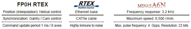
[RTEX communication]
Command update cycle: 1 ms / 8 axes
Check the MINAS data on Web sever
- Basic information
Monitor position, speed, torque, driver part No., motor part No. - Error information
Error code
Error history - Status display
Servo drive inside temperature Encoder inside temperature Deterioration diagnosis
Features of RTEX (Realtime Express)
Simpler wiring: cuts labor time for design and installation.
High speed network and high performance servo bring synchronous control
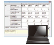
Easily configure parameters and positioning actions
Capable of easily configure parameters and positioning actions by activating Configurator PM7-RTEX from Control FPWIN Pro7.
* For Configurator PM7-RTEX, supported from Control FPWIN Pro7 Ver.7.3.0.0 or later / Control FPWIN GR7 Ver.2.26.0 or later.

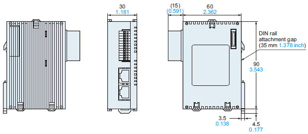
Ultra-compact size inherited from FPΣ
Ultra-compact size of 90 mm 3.543 in in height contributes to the reduction in size of a device.
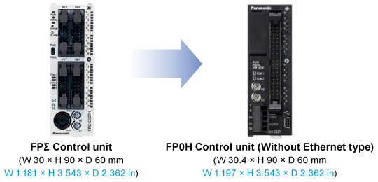
Ladder programs for FPΣ can be converted for FP0H.
Ladder programs for FPΣ created in Control FPWIN GR/GR7 can be converted for FP0H.
Creating new ladder programs are not required when replacing FPΣ with FP0H.
Note: When an unsupported instruction (F176 SPCH: arc interpolation) is used, convert it before model switching.
Applications
Distributed control
■ Distributed devices result in a flexible line, reducing man-hours.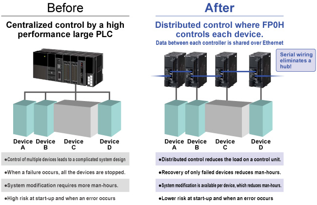
Control of gantry mechanism [FP0H Positioning RTEX units]
2-axis gantry control together with interpolation control enables smooth and highly accurate stage control.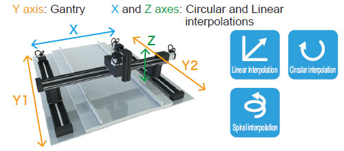
Main application sectors:
Electronic parts, liquid crystal manufacturing, machine tools, etc.
Main application devices:
Inspection equipment, coaters, laser scanners, etc.
Control of cam mechanism [FP0H Positioning RTEX units]
Preset cam operation synchronized with the main axis enables control of the rotation of the slave axis motor.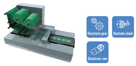
Main application sectors:
Packaging equipment, food/chemicals, general machinery, etc.
Main application devices:
Rotary cutters, printing machine, inserters, etc.
Photographing by camera in a set position [FP0H Positioning RTEX units]
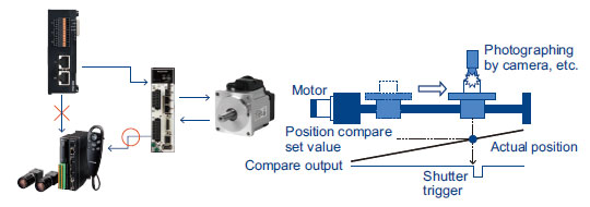
■Highly accurate position compare
Turns trigger output ON in the position of the encoder of servo motor
[Point]
Capable of high-precision timing detection, because position comparison is performed inside the servo motor to avoid communication delay or calculation lag with the controller
Press fitting control with torque stopping [FP0H Positioning RTEX units]
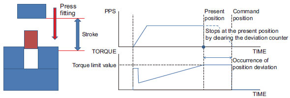
■Deviation counter clearing
Capable of simple press fitting control (torque control) by combining the torque control function at the position control. Stops the motor with the torque limit value, and then stops the occurrence of torque.
[Point]
Stops the application of torque. Capable of immediate inversion operation as there is no accumulated pulse in the deviation counter.
Cueing hoop material [FP0H Positioning RTEX units]
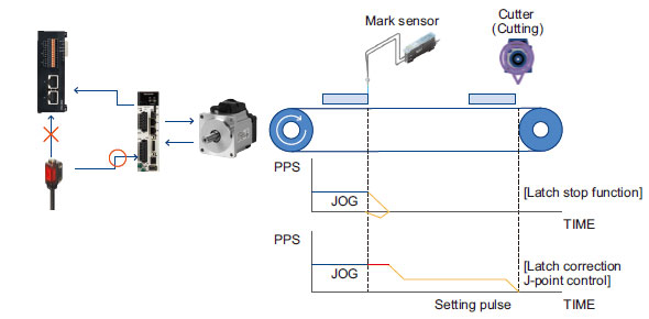
■Latch stop function
Stops the motor immediately by turning ON the sensor signal connected to the servo driver.
■Latch correction J-point control
Stops the motor at a set amount of movement, after turning ON the sensor signal connected to the servo driver.
[Point]
Capable of stopping with high accuracy, because the sensor signal is directly input into the servo driver to avoid communication delay or calculation lag with the controller via the network.
Units
Control units
| Product name | Number of I/O points | Rated voltage | Input specifications | Output specifications | Connection method | SD memory card function | Part No. | |
|---|---|---|---|---|---|---|---|---|
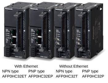
| FP0H control units | Without Ethernet | Input:16 points Output:16 points | 24V DC | 24 V DC (Polarity +/- common) | NPN transistor output: 0.3 A / 0.1 A | MIL connector | - | AFP0HC32T |
| PNP transistor output: 0.3 A | AFP0HC32P | |||||||
| With Ethernet | NPN transistor output: 0.3 A / 0.1 A | Built-in | AFP0HC32ET | |||||
| PNP transistor output: 0.3 A | AFP0HC32EP | |||||||
Expansion I/O unit
| Product name | Number of I/O points | Rated voltage | Input specifications | Output specifications | Connection method | Part No. |
|---|---|---|---|---|---|---|
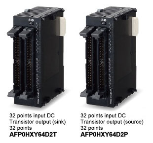
| FP0H expansion I/O unit | Input:32 points Output:32 points | 24V DC | 24 V DC (Polarity +/- common) | NPN transistor output: 0.1 A | MIL connector | AFP0HXY64D2T |
| PNP transistor output: 0.1 A | AFP0HXY64D2P |
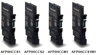
Communication cassettes
| Product name | Specifications | Part No. |
|---|---|---|
| FP0H communication cassettes | RS-232C 1 channel | AFP0HCCS1 |
| RS-232C 2 channels | AFP0HCCS2 | |
| RS-485 1 channel (insulated) | AFP0HCCM1 | |
| RS-232C 1 channel and RS-485 1 channel (insulated) | AFP0HCCS1M1 |
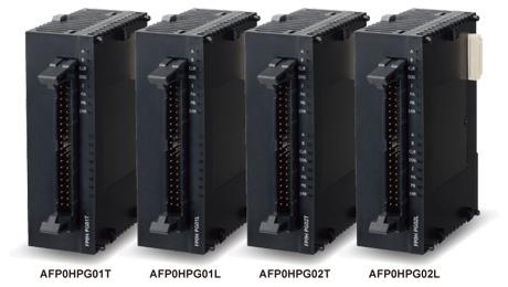
Positioning units
| Product name | Output type | Number of occupied points | Number of axes controlled | Speed command | Part No. |
|---|---|---|---|---|---|
| FP0H positioning units | Transistor | Input 16 points, Output 16 points | 1 axis | 1pps to 500 kpps | AFP0HPG01T |
| Input 32 points, Output 32 points | 2 axes | AFP0HPG02T | |||
| Line driver | Input 16 points, Output 16 points | 1 axis | 1pps to 4 Mpps | AFP0HPG01L | |
| Input 32 points, Output 32 points | 2 axes | AFP0HPG02L |
Positioning RTEX units
| Product name | Occupied I/O points | Number of axes controlled | Part No. | |
|---|---|---|---|---|
| FP0H Positioning RTEX units | 4-axis type | 128 input points, 128 output points | 4 axes | AFP0HM4N |
| 8-axis type | 8 axes | AFP0HM8N | ||
Expansion units (Common to FP0R)
| Product name | Number of I/O points | Rated voltage | Input specications | Output specications | Connection type | Part No. | |
|---|---|---|---|---|---|---|---|
| FP0R-E8 expansion Unit | 8 points | Input: 8 points | - | 24 V DC ±common | - | MIL connector | AFP0RE8X |
| 8 points | Input: 4 points Output: 4 points | 24 V DC | 24 V DC ±common | Relay output: 2 A | Terminal block | AFP0RE8RS | |
| Molex connector | AFP0RE8RM | ||||||
| 8 points | Output: 8 points | 24 V DC | - | Relay output: 2 A | Terminal block | AFP0RE8YRS | |
| 8 points | Output: 8 points | - | - | NPN transistor output: 0.3 A | MIL connector | AFP0RE8YT | |
| 8 points | Output: 8 points | - | - | PNP transistor output: 0.3 A | MIL connector | AFP0RE8YP | |
| FP0R-E16 expansion Unit | 16 points | Input: 16 points | - | 24 V DC ±common | - | MIL connector | AFP0RE16X |
| 16 points | Input: 8 points Output: 8 points | 24 V DC | 24 V DC ±common | Relay output: 2 A | Terminal block | AFP0RE16RS | |
| Molex connector | AFP0RE16RM | ||||||
| 16 points | Input: 8 points Output: 8 points | - | 24 V DC ±common | NPN transistor output: 0.3 A | MIL connector | AFP0RE16T | |
| 16 points | Input: 8 points Output: 8 points | - | 24 V DC ±common | PNP transistor output: 0.3 A | MIL connector | AFP0RE16P | |
| 16 points | Output: 16 points | - | - | NPN transistor output: 0.3 A | MIL connector | AFP0RE16YT | |
| 16 points | Output: 16 points | - | - | PNP transistor output: 0.3 A | MIL connector | AFP0RE16YP | |
| FP0R-E32 expansion Unit | 32 points | Input: 16 points Output: 16 points | - | 24 V DC ±common | NPN transistor output: 0.3 A | MIL connector | AFP0RE32T |
| 32 points | Input: 16 points Output: 16 points | - | 24 V DC ±common | PNP transistor output: 0.3 A | MIL connector | AFP0RE32P | |
Notes:
1) The relay output type expansion units come with a power cable (part number: AFP0581).
(The transistor output type expansion units need no power cable.)
2) The terminal block type relay output units have two terminal blocks (9 pins) made by Phoenix.
Use a 2.5 mm 0.098 in wide screwdriver. Preferably use the specific terminal block screwdriver (Phoenix type code SZS0, 4 x 2.5 mm 0.098 in) or equivalent.
3) The connector type relay output units have two connectors made by Nihon Molex (Molex type code 51067-0900, 9 pins). Use the specific Molex connector press-fit tool (Nihon Molex type code 57189-5000) or equivalent.
4) The transistor output units have a press-fit socket for wire-pressed terminal cable and contacts. Use the press-fit tool (part number: AXY52000FP) for wire-pressed terminal cable.
| Product name | Specications | Product No. | Part No. |
|---|---|---|---|
| FP0R analog input unit | <Input specifications> Number or channels: 4 channels Voltage -10 to +10 V, -5 to +5 V, 0 to +10 V, 0 to +5 V (Resolution: 1/16,000) Current 0 to 20 mA (Resolution: 1/16,000) | - | AFP0RAD4 |
| FP0R analog input unit | <Input specifications> Number or channels: 8 channels Voltage -10 to +10 V, -5 to +5 V, 0 to +10 V, 0 to +5 V (Resolution: 1/16,000) Current 0 to 20 mA (Resolution: 1/16,000) | - | AFP0RAD8 |
| FP0R analog input and output unit | <Input specifications> Number or channels: 2 channels Voltage -10 to +10 V, -5 to +5 V, 0 to +10 V, 0 to +5 V (Resolution: 1/16,000) Current 0 to 20 mA (Resolution: 1/16,000) | - | AFP0RA21 |
| <Output specifications> Number or channels: 1 channel Voltage -10 to +10 V, -5 to +5 V, 0 to +10 V, 0 to +5 V (Resolution: 1/16,000) Current 0 to 20 mA, 4 to 20 mA (Resolution: 1/16,000) | |||
| FP0R analog input and output unit | <Input specifications> Number or channels: 4 channels Voltage -10 to +10 V, -5 to +5 V, 0 to +10 V, 0 to +5 V (Resolution: 1/16,000) Current 0 to 20 mA (Resolution: 1/16,000) | - | AFP0RA42 |
| <Output specifications> Number or channels: 2 channels Voltage -10 to +10 V, -5 to +5 V, 0 to +10 V, 0 to +5 V (Resolution: 1/16,000) Current 0 to 20 mA, 4 to 20 mA (Resolution: 1/16,000) | |||
| FP0R analog output unit | <Output specifications> Number or channels: 4 channels Voltage -10 to +10 V, -5 to +5 V, 0 to +10 V, 0 to +5 V (Resolution: 1/16,000) Current 0 to 20 mA, 4 to 20 mA (Resolution: 1/16,000) | - | AFP0RDA4 |
| FP0 thermocouple units | K, J, T and R thermocouple, 4 channels, Resolution: 0.1 ℃ | FP0-TC4 | AFP0420 |
| K, J, T and R thermocouple, 8 channels, Resolution: 0.1 ℃ | FP0-TC8 | AFP0421 | |
| FP0 CC-Link slave unit | Unit to connect to FP0 CC-link | FP0-CCLS | AFP07943 |
Discontinued products
| Discontinued product | Recommended substitute | |||||
|---|---|---|---|---|---|---|
| Product name | Product number/Part number | Last time buy | Product number/Part number | Product name | Remark | |
| FPΣ Expansion unit | Product number: FPG-XY64D2P Part number: AFPG3567 | September 30, 2021 |
| Product number: AFP0HXY64D2P Part number: AFP0HXY64D2P | FP0H | All units are required to be replaced. |
| FPΣ Expansion unit | Product number: FPG-PN2AN Part number: AFPG43610 | September 29, 2023 |
| Product number: AFP0HM4N Part number: AFP0HM4N | FP0H Positioning RTEX units | To replace the FPΣ positioning unit RTEX, you must also replace the control unit with the FP0H series. |
| FPΣ Expansion unit | Product number: FPG-PN4AN Part number: AFPG43620 | September 29, 2023 |
| Product number: AFP0HM4N Part number: AFP0HM4N | FP0H Positioning RTEX units | To replace the FPΣ positioning unit RTEX, you must also replace the control unit with the FP0H series. |
| FPΣ Expansion unit | Product number: FPG-PN8AN Part number: AFPG43630 | September 29, 2023 |
| Product number: AFP0HM8N Part number: AFP0HM8N | FP0H Positioning RTEX units | To replace the FPΣ positioning unit RTEX, you must also replace the control unit with the FP0H series. |
| Configurator PM | Product number: AFPS66110 Part number: AFPS66110 | September 30, 2024 |
| Product number:- Part number:- | - | Sorry, no suggested alternative products. |
| Configurator PM | Product number: AFPS66510 Part number: AFPS66510 | September 30, 2024 |
| Product number:- Part number:- | - | Sorry, no suggested alternative products. |

Option
Programming tools
For software specifications, please refer to the web page of each software.
>> Refer to "Control FPWIN GR7"
>> Refer to "Control FPWIN Pro7"
| Product name | Type | Part No. | ||
|---|---|---|---|---|
| Programming software for Windows® Control FPWIN GR7 | Japanese version | Supports only CPU unit without encryption function | AFPSGR7JP | |
| Security enhanced type | Supports both CPU unit with / without encryption function | AFPSGR7JPS | ||
| English version | Supports only CPU unit without encryption function | AFPSGR7EN | ||
| Security enhanced type | Supports both CPU unit with / without encryption function | AFPSGR7ENS | ||
| Programming software for Windows® Control FPWIN Pro7 | Japanese English Chinese Korean | Supports only CPU unit without encryption function | AFPSPR7A | |
| Supports both CPU unit with / without encryption function * The encryption function will be offered in the future. | AFPSPR7AS | |||
* Windows is trademarks or registered trademarks of Microsoft Corporation in the United States and other countries.
* When exporting to China, CPU unit without encryption function is required.
Note:
1) Please use a commercially available USB2.0 cable (A type mini B) for connecting a control unit with a PC.
Option
| Product name | Specifications | Part No. |
|---|---|---|
| Backup battery | Required for backup of the data registers and when the calendar timer feature is used. | AFPX-BATT |
Others
| Product name | Appearance | Descriptions | Part No. |
|---|---|---|---|
| Power cable | - | Length: 1 m 3.28 ft Attaches to FP0H control unit. | AFPG805 |
| Scattered wire connector set (40 pins) |
| Supplied with FP0H control unit and FP0H expansion I/O unit.(2 pieces) | AFP2801 |
| Multi-wire connector pressure contact tool |
| Necessary when wiring connectors in the supplied discrete-wire connector set to FP0H control unit or FP0H expansion I/O unit. | AXY52000FP |
| Push-In Connector Set (40-Pole) |
| For FP0H control unit, FP0H expansion I/O unit and FP0H Positioning units.Attachable to MIL connector. (including 2 pieces) | AFP2808 |
| Flat cable connector set (40 leads) |
| For FP0H control unit and FP0H expansion I/O unit. For simple connection using a flat cable. (2 pieces) | AFP2802 |

Specifications
Control units
Control specifications
| Type | Without Ethernet | With Ethernet | |||||
|---|---|---|---|---|---|---|---|
| NPN type | PNP type | NPN type | PNP type | ||||
| Part No. | AFP0HC32T | AFP0HC32P | AFP0HC32ET | AFP0HC32EP | |||
| Number of controllable I/O points | 32 points (Input: 16, Output: 16), When expanded: Max. 384 points | ||||||
| Programming method / Control method | Relay symbol / Cyclic operation | ||||||
| Program memory | Built-in flash ROM (no backup battery required) | ||||||
| Number of instructions | Basic instructions | 120 types approx. | |||||
| High-level instructions | 240 types approx. | 270 types approx. | |||||
| Program capacity | 24 k /32 k steps | 24 k /32 k /40 k / 64 k steps | |||||
| Can be selected at system register No. 0 When the program capacity is changed, the number of words that can be used in the data register (DT) is also changed.
| |||||||
| Operation speed | Basic instruction (NOT: /) : 10 ns/step approx. (Up to 10 k steps) , 0.18 μs/step approx. (10 k steps and later) Basic instruction (ST) : 40 ns/step approx. (Up to 10 k steps) , 0.65 μs/step approx. (10 k steps and later) High-level instruction (FOMV) : 0.14 μs/step approx. (Up to 10 k steps) , 1.2 μs/step approx. (10 k steps and later) | ||||||
| Base scan time I/O refresh and base time | Control unit: 40 μs or less approx. and FP0 / FP0R expanshion unit refresh time (Note 1) | Control unit: 100 μs or less approx. and FP0 / FP0R expanshion unit refresh time (Note 1) | |||||
| Operation memory | Relay | External input (X) (Note 2, 3) | 1, 760 points (X0 to X109F) | ||||
| External output (Y) (Note 2, 3) | 1, 760 points (Y0 to Y109F) | ||||||
| Internal relay (R) (Note 3) | 4,096 points (R0 to R255F) or 8,192 points (R0 to R511F) (Note 4) | 8,192 points (R0 to R511F) | |||||
| Special internal relay (R) | 800 points (R9000 to R951F) | ||||||
| Timer / Counter (T / C) (Note 5) | 1,024 points (initial setting, timer: 1,008 points, counter: 16 points) | ||||||
| Link relay (L) | 2,048 points (L0 to L127F) | ||||||
| Memory area | Data register (DT) (Note 6) | 32,765 words or 65,533 words | 12,285 words or 24,573 words or 32,765 words or 65,533 words | ||||
| Special data register (DT) (Note 3) | 1,000 words (DT90000 to DT90999) | ||||||
| Link data register (LD) | 256 words (LD0 to LD255) | ||||||
| Index register (I) | 14 words (I0 to ID) | ||||||
| Differential points | Points for the program capacity | ||||||
| Number of master control relay (MCR) | 256 points | ||||||
| Number of labels (JP and LOOP) | 256 points | ||||||
| Number of step ladder | 1,000 stages | ||||||
| Number of subroutines | 500 subroutines | ||||||
| Number of interrupt program | 9 programs •Input: 8 programs (INT0 to INT7) •Periodic: 1 program (INT24) | ||||||
| Sampling trace (Note 7) | Available [Sampling by commands / Sampling at regular time intervals (For one sampling: 16 bits + 3 words), 1,000 samples] | ||||||
| Comment storage | I/O comments, remarks and block comments can be stored. (no backup battery required, 1 M byte) | ||||||
| PLC link function (Serial communication) | Max. 16 units, link relays: 1,024 points, link registers: 128 words. (Data transfer and remote programming are not supported) | ||||||
| Constant scan | Available (0 to 600 ms) | ||||||
| Password | Available (32 digits) | ||||||
| Program upload protection | Available | ||||||
| Program protect function | Available | ||||||
| Self-diagnostic function | Watchdog timer, program syntax check, etc. | ||||||
| Program edition during RUN | Available | ||||||
| SD memory card function | - | SD memory card project copy, Logging trace function (Note 7), SD memory card access instruction | |||||
| Memory transfer | Available [Built-in memory (ROM ⇔ RAM)] | ||||||
| High speed counter (Note 8) | Main unit input | Single-phase 4 channels (Max. 100 kHz each input) or 2-phase 2 channels (Max. 50 kHz each input) | |||||
| Pulse output (Note 8) | Main unit output | 4 channels (Max. 100 kHz each axis) | |||||
| PWM output (Note 8) | Main unit output | 4 channels (1 Hz to 70 kHz: 1,000 resolution / 70.001 kHz to 100 kHz: 100 resolution | |||||
| Pulse catch input Interrupt input | Total 8 points (with high speed counter) | ||||||
| Periodical interrupt | 0.1 ms to 30 sec. | ||||||
| Potentiometer (Volume) input | 2 channels (0 to 4000) | Not available | |||||
| Clock / calendar (Note 9, 10) | Year (last two digits), month, day, hour (24-hour display), minute, second and day of week | ||||||
| Memory backup (Note 11) | Backup by instruction P13 | Data register: all area | |||||
| Auto-backup at power failure | Counter: 16 points Internal relay: 128 points Data register: 315 words | ||||||
| Battery backup (only when a battery is installed) | Hold areas or non-hold areas can be specified by setting the system registers No.6 to No. 13. (It is also possible to make the setting for hold all points.) | ||||||
| Battery life | 5 years or more under a production condition (operates for 8 hours per day) | ||||||
Note:
1) Refresh times for FP0 / FP0R expansion units
8 points unit : Number of units×0.8ms
16 points unit : Number of units×1.0ms
32 points unit : Number of units×1.3ms
64 points unit : Number of units×1.9ms
2) The number of points that can be used depends on the combination of hardware.
3) Some specifications are compatible with FPΣ.
4) System register No. 1 (internal relay capacity) can be configured to select "0: 4,096 points / 1: 8,192 points".
5) An auxiliary timer instruction (F137) can be used to add the number of points.
6) System register No. 0 (program capacity) can be configured to select the capacity of the data register (DT).
7) Logging trace and sampling trace cannot be used at the same time.
8) The specifications are based on the rated input voltage of 24 V DC at +25 ℃ +77 ℉. The maximum operation frequency may be lower depending on the applied voltage, ambient temperature, and conditions of use. The maximum operation frequency varies depending on how the unit is used.
9) Accuracy of the clock / calendar (within ± 90 seconds per month at +25 ℃ +77 ℉).
If an error of the clock / calendar becomes a problem in the system, set an accurate time periodically.
10) If the battery is not attached, calendar information is cleared when the power is turned off. It will be necessary to set the date when the power is turned on.
11) Data can be rewritten up to 10,000 times. Hold / non-hold areas can be specified in the system registers.
General specifications
| Type | Without Ethernet | With Ethernet | ||
|---|---|---|---|---|
| NPN type | PNP type | NPN type | PNP type | |
| Part No. | AFP0HC32T | AFP0HC32P | AFP0HC32ET | AFP0HC32EP |
| CE marking directive compliance | EMC Directive, RoHS Directive | |||
| Rated voltage | 24 V DC | |||
| Operating voltage range | 20.4 to 28.8 V DC | |||
| Consumption current | 140 mA or less | 170 mA or less | ||
| Allowed momentary power off time | 4 ms (at 20.4 V DC), 10 ms (24 V DC or higher) | |||
| Ambient temperature | 0 to +55 ℃ +32 to +131 ℉, At storage: -40 to +70 ℃ - 40 to +158 ℉ | |||
| Ambient humidity | 10 to 95 % RH (at +25 ℃ +77 ℉, no dew condensation allowed), At storage: 10 to 95 % RH (at +25 ℃ +77 ℉, no dew condensation allowed) | |||
| Breakdown voltage (Detection current: 5 mA) | 500 V AC for 1 minute Input and output terminals ⇔ power and functional ground terminals Input terminals ⇔ Output terminals | |||
| Insulation resistance (Test voltage: 500 V DC) | 100 MΩ or more Input and output terminals ⇔ power and functional ground terminals Input terminals ⇔ Output terminals | |||
| Vibration resistance | 5 to 8.4 Hz, single amplitude of 3.5 mm 0.138 in, 8.4 to 150 Hz, constant acceleration of 9.8 m/s2, for 10 times each in X, Y, and Z directions (1 octave/min.) (JIS B 3502, IEC 61131-2) | |||
| Shock resistance | 147 m/s2, 4 times each in X, Y, and Z directions (JIS B 3502, IEC 61131-2) | |||
| Noise immunity | 1,000 V (p-p) with pulse widths 50 ns and 1 μs (using a noise simulator) (Power supply terminal) | |||
| Operating condition | Free from corrosive gasses and excessive dust | |||
| Overvoltage category | Category II | |||
| Degree of pollution | Pollution level 2 | |||
| Net weight | 110 g approx. each | 130 g approx. each | ||
COM0 port communication specifications
| Item | Specifications | |
|---|---|---|
| Interface | RS-232C, three-wire system, 1 channel (Not insulated) | |
| Transmission distance | 15 m 49.213 ft | |
| Communication configuration | 1 : 1 communication | |
| Communication method | Half-duplex system | |
| Synchronous method | Start-stop synchronization system | |
| Transmission cable | Multi-conductor shielded wire | |
| Communication speed (Specified at the system registers) | 1,200(Note 3), 2,400(Note 3), 4,800, 9,600, 19,200, 38,400, 57,600, 115,200, 230,400 bits/sec. | |
| Transmission format | Data length | 7 bits / 8 bits |
| Parity | none / odd / even | |
| Stop bit | 1 bit / 2 bits | |
| Start code | with STX / without STX | |
| End code | CR / CR + LF / none / ETX / Time (0 to 100.00 ms) | |
| Data transmission order | Transmit from bit 0 in character units | |
| Communication mode | MEWTOCOL-COM (Master / Slave) (Computer link) General-purpose communication PLC link MODBUS RTU (Master / Slave) | |
Notes:
1) The start and end codes can be used only for general-purpose serial communications.
2) The unit No. (station number) can be selected at system register No. 410.
3) System register no. 415 cannot be used to set the baud rate to 1,200 bps. To set the baud rate to 1,200 bps, use the SYS1 instruction. If the baud rate of any of the COM ports is 2,400 bps or lower, F-ROM access will slow down.
Example) F12(ICRD) instruction, P13(ICWT) instruction, etc.
LAN port communication specifications (for only Ethernet type)
| Item | Specifications |
|---|---|
| Communication interface | Ethernet 100BASE-TX / 10BASE-T |
| Baud rate | 100 Mbps, 10 Mbps auto negotiation function |
| Total cable length | 100 m 328.084 ft (500 m 1640.420 ft when a repeater is used) |
| Number of simultaneous connections | Max. 10 (system connection: 1, user connection: 9) |
| Communication method | Full duplex / Half-duplex system |
| Communication protocol (Communication layer) | TCP / IP, UDP |
| DNS | Supports name servers |
| DHCP | Automatic IP address acquisition |
| FTP server / Client | File transmission, server function, No. of users:1 Client function, Data file transfer |
| SNTP | Time adjustment function |
| General-purpose communication | 4 kB / 1 connection (user connection: 1 to 9) (Note 2) |
| Dedicated communication | EtherNet/IP MEWTOCOL-COM (Master / Slave) (Computer link) MODBUS-TCP (Master / Slave) MEWTOCOL-DAT (Master / Slave) General-purpose communication MC protocol (Note 1) (Master / Slave) |
Notes:
1) MC protocol is a short form denoting MELSEC communication protocol; MELSEC is a registered trademark of Mitsubishi Electric Corporation.
QnA compatible 3E frame, only binary (bulk writing and bulk reading) use is available.
2) General-purpose communications can be up to 4 kB (reception) and up to 2 kB (transmission) per connection.
USB port specifications
| Item | Specifications |
|---|---|
| Standard | USB2.0 Full speed (USB mini B type) |
| Communication function | Computer link (slave) |
Dedicated power supply output port specifications for GT series programmable display
| Output terminal | Connecting programmable display model |
|---|---|
| 5 V DC | For 5 V DC type GT02 series Programmable Display |
Input specifications
| Item | Specifications | |
|---|---|---|
| Rated input voltage | 24 V DC | |
| Operating voltage range | 21.6 to 26.4 V DC | |
| Rated input current | High-speed part (X0 to X7) : 8 mA approx. Low-speed part (X8 to XF) : 3.5 mA approx. | |
| Input points per common | 16 points/common (Either the positive or negative of the input power supply can be connected to the common terminal.) | |
| Min. ON voltage / Min. ON current | High-speed part (X0 to X7) : 19.2 V DC / 6 mA Low-speed part (X8 to XF) : 19.2 V DC / 3 mA | |
| Max. OFF voltage / Max. OFF current | 2.4 V DC / 1 mA | |
| Input impedance | High-speed part (X0 to X7) : 3 kΩ approx. Low-speed part (X8 to XF) : 6.8 kΩ approx. | |
| Response time (Note) | OFF → ON | <High-speed part (X0 to X7)> 135 μs or less: normal input 5 μs or less: high speed counter, pulse catch, interrupt input settings <Low-speed part (X8 to XF)> 1 ms or less: normal input only |
| ON → OFF | Same as above | |
| Operating mode indicator | LED display | |
Note: The input time constant (0.1 to 256 ms) can be specified.
Output specifications
| Type | Without Ethernet | With Ethernet | Without Ethernet | With Ethernet | |
|---|---|---|---|---|---|
| Part No. | AFP0HC32T | AFP0HC32ET | AFP0HC32P | AFP0HC32EP | |
| Output type | Nch open drain | Pch open drain | |||
| Rated load voltage | 5 to 24 V DC | 24 V DC | |||
| Operating load voltage range | 4.75 to 26.4 V DC | 21.6 to 26.4 V DC | |||
| Rated load current | 0.3 A (For Y0, Y1, Y3, Y4, Y8,Y9, YB,YC), 0.1 A (For Y2, Y5, Y6, Y7, YA, YD, YE, YF) | 0.3 A (For Y0 to YF) | |||
| Max. surge current | High-speed part (For Y0, Y1, Y3, Y4, Y8, Y9, YB, YC) : 1.0 A, Low-speed part (For Y2, Y5, Y6, Y7, YA, YD, YE, YF) : 0.5 A | ||||
| OFF state leakage current | 110 μA or less | 20 μA or less | |||
| ON state voltage drop | 0.5 V DC or less | ||||
| Overcurrent protection | Provided (automatically protected for each 8 points) | ||||
| Output points per common | 16 points/common (Y0 to YF / 1 common) | ||||
| Response time | OFF → ON | High-speed part (For Y0, Y1, Y3, Y4, Y8, Y9, YB, YC) : 2 μs or less, Low-speed part (For Y2, Y5, Y6, Y7, YA, YD, YE, YF) : 1 ms or less | |||
| ON → OFF | High-speed part (For Y0, Y1, Y3, Y4, Y8, Y9, YB, YC) : 5 μs or less, Low-speed part (For Y2, Y5, Y6, Y7, YA, YD, YE, YF) : 1 ms or less | ||||
| Surge absorber | Zener diode | ||||
| Operating mode indicator | LED display | ||||
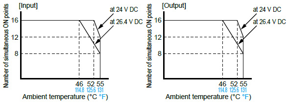
Limitations on simultaneous ON points
Current consumption
| Type of unit | Control unit current consumption (at 24 V DC) | Additional current (at 24 V DC) | Expansion unit current consumption (at 24 V DC) | |
|---|---|---|---|---|
| Control unit alone | AFP0HC32T | 140 mA or less | - | - |
| AFP0HC32P | ||||
| AFP0HC32ET | 170 mA or less | |||
| AFP0HC32EP | ||||
| Extension unit attached | AFP0HXY64D2T | - | 35 mA or less | - |
| AFP0HXY64D2P | ||||
| AFP0HPG01T | 50 mA or less | 20 mA or less | ||
| AFP0HPG01L | ||||
| AFP0HPG02T | 70 mA or less | 35 mA or less | ||
| AFP0HPG02L | ||||
| AFP0HM4N | 90 mA or less | - | ||
| AFP0HM8N | ||||
| Extension cassette attached | AFP0HCCS1 | - | 10 mA or less | - |
| AFP0HCCS2 | ||||
| AFP0HCCM1 | 30 mA or less | |||
| AFP0HCCS1M1 | ||||
Expansion I/O unit
General specifications
| Item | Specifications |
|---|---|
| Ambient temperature | 0 to +55 ℃ +32 to +131 ℉, At storage: -20 to +70 ℃ - 4 to +158 ℉ |
| Ambient humidity | 30 to 85 % RH (at +25 ℃ +77 ℉, no dew condensation allowed), At storage: 30 to 85 % RH (at +25 ℃ +77 ℉, no dew condensation allowed) |
| Breakdown voltage (Detection current: 5 mA) | 500 V AC for 1 minute Input and output terminals ⇔ power and functional ground terminals (at control unit) Input terminals ⇔ Output terminals |
| Insulation resistance (Test voltage: 500 V DC) | 100 MΩ or more Input and output terminals ⇔ power and functional ground terminals (at control unit) Input terminals ⇔ Output terminals |
| Vibration resistance | 10 to 55 Hz, 1 sweep/min., double amplitude of 0.75 mm 0.030 in, 10 minutes each in X, Y, and Z directions |
| Shock resistance | 98 m/s2, 4 times each in X, Y, and Z directions |
| Noise immunity | 1,000 V (p-p) with pulse widths 50 ns and 1 μs (using a noise simulator) |
| Operating condition | Free from corrosive gasses and excessive dust |
| Net weight | 100 g approx. |
| Control unit's additional consumption current | 35 mA or less (at 24 V DC) [100 mA or less (internal 5 V DC)] |
Input specifications
| Item | Specifications | |
|---|---|---|
| Insulation method | Photocoupler | |
| Rated input voltage | 24 V DC | |
| Operating voltage range | 21.6 to 26.4 V DC | |
| Rated input current | 3.5 mA approx. | |
| Input points per common | 32 points/common (Either the positive or negative of the input power supply can be connected to the common terminal.) | |
| Min. ON voltage / Min. ON current | 19.2 V DC / 3 mA | |
| Max. OFF voltage / Max. OFF current | 2.4 V DC / 1.3 mA | |
| Input impedance | 6.8 kΩ approx. | |
| Response time | OFF→ON | 0.2 ms or less |
| ON→OFF | 0.3 ms or less | |
| Operating mode indicator | LED display | |
Output specifications
| Type | Sink | Source | |
|---|---|---|---|
| Part No. | AFP0HXY64D2T | AFP0HXY64D2P | |
| Insulation method | Photocoupler | ||
| Output type | Open collector (NPN) | Open collector (PNP) | |
| Rated load voltage | 5 to 24 V DC | 24 V DC | |
| Operating load voltage range | 4.75 to 26.4 V DC | 21.6 to 26.4 V DC | |
| Rated load current | 0.1 A | ||
| Max. surge current | 0.5 A | ||
| Output points per common | 32 points/common | ||
| OFF state leakage current | 100 μA or less | ||
| ON state voltage drop | 0.5 V DC or less | ||
| Response time | OFF → ON | 0.2 ms or less | |
| ON → OFF | 0.5 ms or less | ||
| External power supply (for driving internal circuit) | Voltage | 21.6 to 26.4 V DC | |
| Current | 35 mA or less | 40 mA or less | |
| Surge absorber | Zener diode | ||
| Operating mode indicator | LED display | ||
| Short circuit protection | Short circuit protection, Thermal protection | ||
Number of simultaneous ON points

Communication cassettes
Specifications
| Item | Specifications | |||||
|---|---|---|---|---|---|---|
| AFP0HCCS1 | AFP0HCCS2 | AFP0HCCM1 | AFP0HCCS1M1 | |||
| Interface | RS-232C 1 channel | RS-232C 2 channels | RS-485 1 channel | RS-232C 1 channel and RS-485 1 channel | ||
| Transmission distance | Max. 15 m 49.213 ft | Max. 1,200 m 3,937.008 ft | RS-232C Max. 15 m 49.213 ft | RS-485 Max. 1,200 m 3,937.008 ft | ||
| Communication configuration | 1 : 1 communication | 1 : N communication | 1 : 1 communication | 1 : N communication | ||
| Communication speed | 1,200(Note 1), 2,400(Note 1), 4,800, 9,600, 19,200, 38,400, 57,600, 115,200, 230,400 bits/sec. | |||||
| Communication method | Half-duplex system | |||||
| Synchronous method | Start-stop synchronization system | |||||
| Transmission format | Data length | 7 bits / 8 bits | ||||
| Parity | none / odd / even | |||||
| Stop bit | 1 bit / 2 bits | |||||
| Start code | with STX / without STX | |||||
| End code | CR / CR + LF / none / ETX / Time (0 to 100 ms) | |||||
| Data transmission order | Transmit from bit 0 in character units. | |||||
| Number of stations | - | - | Max. 99 units | - | Max. 99 units | |
| Net weight | 10 g approx. each | |||||
Notes:
1) System register no. 415 cannot be used to set the baud rate to 1,200 bps. To set the baud rate to 1,200 bps, use the SYS1 instruction. If the baud rate of any of the COM ports is 2,400 bps or lower, F-ROM access will slow down.
Example) F12(ICRD) instruction, P13(ICWT) instruction, etc.
2) The start and end codes can be used only for general-purpose serial communications.
3) The unit No. (station number) can be selected at system register.
4) Sufficient noise tolerance is provided but it is recommended that a user program be created for retransmission. (To improve the reliability of communications when a communication error occurs due to an excessive noise or when the target device cannot receive data temporarily.)
5) When connecting a commercially available device that has an RS-485 interface, please confirm operation using the actual device. In some cases, the number of station units, transmission distance and communication speed vary depending on the connected device.
6) The transmission distance, transmission speed, and number of stations should be within the range of the graph below, depending on each value.
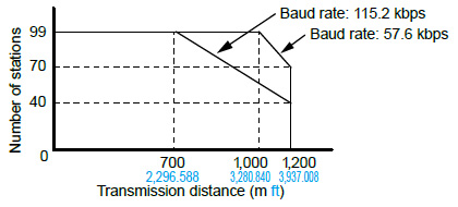
When the transmission speed is 19,200 bits/s, you can set up to 99 stations and up to 1,200 m3,937.008 fttransmission distance.
Positioning units
Specifications
| Part No. | AFP0HPG01T | AFP0HPG01L | AFP0HPG02T | AFP0HPG02L | |
|---|---|---|---|---|---|
| Output type | Transistor | Line driver | Transistor | Line driver | |
| Number of occupied points | Input 16 points, Output 16 points | Input 32 points, Output 32 points | |||
| Number of axes controlled | 1 axis | 2 axes, independent | |||
| Position command | Command units | Pulse unit (The program specifies whether Increment or Absolute is used.) | |||
| Max. pulse count | Signed 32 bits (-2,147,483,648 to +2,147,483,647 pulses) | ||||
| Speed command | Command range | 1 pps to 500 kpps (can set in 1 pps.) | 1 pps to 4 Mpps (can set in 1 pps.) | 1 pps to 500 kpps (can set in 1 pps.) | 1 pps to 4 Mpps (can set in 1 pps.) |
| Acceleration / deceleration command | Acceleration / deceleration method | Linear acceleration / deceleration, S acceleration / deceleration | |||
| S-curve type | Can select from Sin curve, Secondary curve, Cycloid curve and Third curve. | ||||
| Acceleration / deceleration time | 0 to 32,767 ms (can set in 1 ms) | ||||
| Home return | Home return speed | Speed setting possible (changes return speed and search speed) | |||
| Input signal | Home input, Near home input, Over limit input (+), Over limit input (-) | ||||
| Output signal | Deviation counter clear signal | ||||
| Operation mode | E point control (Linear accelerations / decelerations, S accelerations / decelerations) P point control (Linear accelerations / decelerations, S accelerations / decelerations) Home return function (Home search) JOG operation function (Note 1) JOG positioning function Pulser input function (Note 3) • Transfer multiplication ratio (× 1, × 2, × 5, × 10, × 50, × 100, × 500, × 1000) Real-time frequency change function Infinity output function | ||||
| Startup time | 0.02 ms or 0.005 ms selectable (Note 2) | ||||
| Output interface | Output mode | 1 pulse output (Pulse and Sign), 2-pulse output (CW and CCW) | |||
| Feed back counter function (Note 3) | Countable range | Signed 32 bits (-2,147,483,648 to +2,147,483,647 pulses) | |||
| Input mode | Two-phase input, Direction distinction input, Individual input (transfer multiple available for each.) | ||||
| Other functions | The flag to compare the elapsed value is built in. (The timing signal outputs at the optional position during an operation.) | ||||
| External power supply | Voltage | 21.6 to 26.4 V DC | |||
| Current consumption | 20 mA | 30 mA | |||
| Net weight | 75 g approx. each | 80 g approx. each | |||
Positioning RTEX units
Specifications
| Type | 4-axis type | 8-axis type | ||||
|---|---|---|---|---|---|---|
| Part No. | AFP0HM4N | AFP0HM8N | ||||
| Number of axes controlled | 4 axes | 8 axes | ||||
| Interpolation control | 2-axis linear interpolation, 2-axis circular interpolation, 3-axis linear interpolation and 3-axis spiral interpolation | |||||
| Occupied I/O points | 128 input points, 128 output points | |||||
| Automatic operation | Position control | Position specification mode | Absolute (Absolute position specifi cation), Increment (Relative position specifi cation) | |||
| Position specified unit | pulse μm (Min. unit of instruction selectable between 0.1 μm and 1 μm) inch (Min. unit of instruction selectable between 0.00001 inch and 0.0001 inch) degree (Min. unit of instruction selectable between 0.1 degree and 1 degree) | |||||
| Position setting range | pulse : -2,147,482,624 to 2,147,482,624 pulse μm (0.1 μm) : -214,748,262.4 to 214,748,262.4 μm μm (1 μm) : -2,147,482,624 to 2,147,482,624 μm inch (0.00001 inch) : -21,474.82624 to 21,474.82624 inch inch (0.0001 inch) : -214,748.2624 to 214,748.2624 inch degree (0.1 degree) : -214,748,262.4 to 214,748,262.4 degree degree (1 degree) : -2,147,482,624 to 2,147,482,624 degree | |||||
| Speed reference range | pulse : 1 to 2,147,482,624 pps μm : 1 to 2,147,482,624 μm/s inch : 0.001 to 2,147,482.624 inch/s degree : 0.001 to 2,147,482.624 rev/s | |||||
| Acceleration and deceleration method | Linear acceleration / deceleration, S acceleration / deceleration | |||||
| Acceleration time | 0 to 10,000 ms (Settable by 1 ms) | |||||
| Deceleration time | 0 to 10,000 ms (Settable by 1 ms) | |||||
| No. of positioning tables | Each axis : 600 points in standard area and 89 points in extended area | |||||
| Control method | Independent | PTP control (E-point control, C-point control), CP control (P-point control), Speed control (J-point control) | ||||
| 2-axis interpolation | Linear interpolation | E point, P point, C point controls, Composite speed or Long axis speed | ||||
| Circular interpolation | E point, P point, C point controls, Center point or Pass point | |||||
| 3-axis interpolation | Linear interpolation | E point, P point, C point controls, Composite speed or Long axis speed | ||||
| Spiral interpolation | E point, P point, C point controls, Center point or Pass point | |||||
| Startup time | Standard area : 3 ms or less, Extended area : 5 ms or less | |||||
| Other functions | Dwell time | 0 to 32,767 ms (Settable by 1 ms) | ||||
| Manual operation | JOG operation | Speed reference range | pulse : 1 to 2,147,482,624 pps μm : 1 to 2,147,482,624 μm/s inch : 0.001 to 2,147,482.624 inch/s degree : 0.001 to 2,147,482.624 rev/s | |||
| Acceleration / deceleration method | Linear acceleration / deceleration, S acceleration / deceleration | |||||
| Acceleration time | 0 to 10,000 ms (Settable by 1 ms) | |||||
| Deceleration time | 0 to 10,000 ms (Settable by 1 ms) | |||||
| Home return (Note) | Speed reference range | pulse : 1 to 2,147,482,624 pps μm : 1 to 2,147,482,624 μm/s inch : 0.001 to 2,147,482.624 inch/s degree : 0.001 to 2,147,482.624 rev/s | ||||
| Acceleration / deceleration method | Linear acceleration/deceleration | |||||
| Acceleration time | 0 to 10,000 ms (Settable by 1 ms) | |||||
| Deceleration time | 0 to 10,000 ms (Settable by 1 ms) | |||||
| Return method | DOG method (3 types), Limit method (2 types), Data set method, Z phase method, Stop-on-contact method (2 types) | |||||
| Pulsar operation | Speed reference range | Operation synchronized with inputs from pulser | ||||
| Stop function | Deceleration stop | Deceleration time | Deceleration time of the operation being active | |||
| Emergency stop | Deceleration time | 0 to 10,000 ms (Settable by 1 ms) | ||||
| Limit stop | Deceleration time | 0 to 10,000 ms (Settable by 1 ms) | ||||
| Error stop | Deceleration time | 0 to 10,000 ms (Settable by 1 ms) | ||||
| System stop | Deceleration time | Immediate stop (0 ms) | ||||
| Synchronous functions | Supported functions | Electronic gear, Electronic clutch, Electronic cam | ||||
| No. of axes | No. of synchronous groups | 4 groups | ||||
| Master axis | Selectable from real axes, virtual axes and pulse inputs. | |||||
| Slave axis | Max. 8 axes per master axis | |||||
| Electronic gear | Operation setting | Gear ratio setting | ||||
| Operation method | Direct method, Linear acceleration / deceleration method | |||||
| Electronic clutch | Trigger type | Clutch ON trigger : Contact method Clutch OFF trigger : Contact input, The contact input + phase specifi cation Contact method can be selected from the edge and level types. | ||||
| Connection method | Direct method, Linear slide method | |||||
| Electronic cam | Cam curve | Select from 20 types. Multiple curves can be specifi ed within phase (0 to 100 %) | ||||
| Resolution | 1,024, 2,048, 4,096, 8,192, 16,384, 32,768 | |||||
| No. of cam patterns | 4 to 16 (According to resolution) | |||||
| Cam pattern configuration method | Cam curve method, Cam point method (set from Confi gurator PM7-RTEX) | |||||
| Other specifications | Software limit function | Setting range | pulse : -2,147,482,624 to 2,147,482,624 pulse μm (0.1 μm) : -214,748,262.4 to 214,748,262.4 μm μm (1 μm) : -2,147,482,624 to 2,147,482,624 μm inch (0.00001 inch) : -21,474.82624 to 21,474.82624 inch inch (0.0001 inch) : -214,748.2624 to 214,748.2624 inch degree (0.1 degree) : -214,748,262.4 to 214,748,262.4 degree degree (1 degree) : -2,147,482,624 to 2,147,482,624 degree | |||
| Monitor judgement | Torque judgement | Torque judgement : Selectable from Enabled / Disabled, Error / Warning 0.0 to 500.0 % | ||||
| Actual speed judgement | Actual speed judgement : Selectable from Enabled / Disabled, Error / Warning 0 to 5,000 rpm | |||||
| Backup | Parameters and positioning data are saved in the fl ash memory. (Battery less) | |||||
| ・ Limit input CWL, CCWL monitor, Proximity (DOG) monitor ・ General-purpose input : 2 points, General-purpose output : 2 points (input and output from driver) ・ Auxiliary output contact, Auxiliary output code ・ Torque limit function | ||||||
(Note) : "Servo motor with an absolute encoder" supported Absolute home return is performed in combination with A6-family servo motor with an absolute encoder.
For servo drivers of A6NF and A6NE. Servo drivers with software of Ver. 1.24 (A6NF and A6NE) or later supported
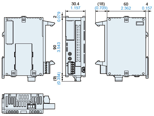
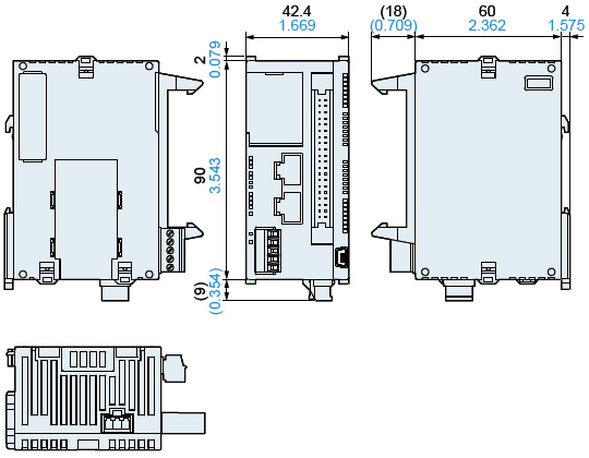
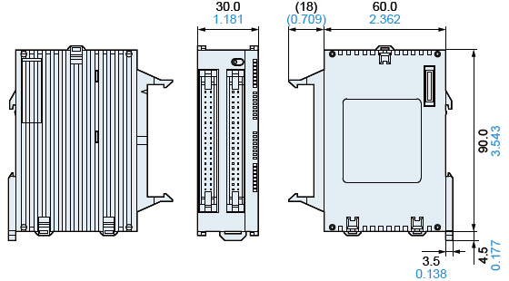
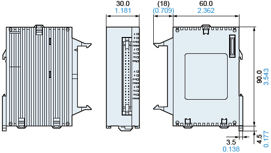
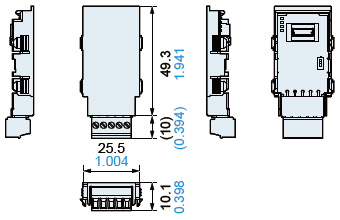
Dimensions
- Unit: mm in
AFP0HC32T
AFP0HC32P
Control units
AFP0HC32ET
AFP0HC32EP
Control units
AFP0HXY64D2T
AFP0HXY64D2P
Expansion I/O units
AFP0HPG01T
AFP0HPG01L
AFP0HPG02T
AFP0HPG02L
Positioning units
AFP0HCCS1
AFP0HCCS2
AFP0HCCM1
AFP0HCCS1M1
Communication cassettes
AFP0HM4N
AFP0HM8N
Positioning RTEX units