------------------------------ Tab1 showing ------------------------------
Basic Information

Compact terminal block type controller
Superior basic performance and wealth of functions


UL:Excluding AFPX-RTD2
 June 2021 - PNP type is added to the lineup!
Features
Compact terminal block type controller
Superior basic performance and wealth of functions
High-speed operation
Large capacity program memory
- Basic instruction (ST instruction): 0.04 μs/step
Up to 7 k steps (ratio to convention: 8 times)
- Program capacity: Max. 40 k steps (For C14: 16 k steps), 24 k / 32 k / 40 k steps selectable
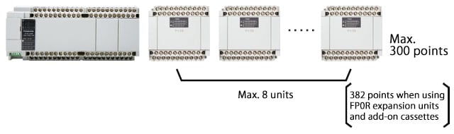
- Max. I/O points: 300 points
One control unit connectable to up to 8 expansion units (382 points when using FP0R expansion units and add-on cassettes) - Up to 4 add-on cassettes can be added (C14: up to 2 add-on cassettes)
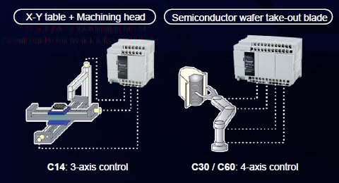
Multi-axis positioning control
- On up to 6 axes, built-in 100 kHz high-speed pulse output function
(Transistor output type has a built-in pulse output function for 3 axes for C14, 4 axes for C30 and 6 axes for C60)
Network
- Communication port: Max. 5 channels
Support for up to 5 channels including 2 communication cassettes (2 channels type) and tool port. - Compatible with Modbus-RTU
Compatible with master / slave of Modbus-RTU, industry standard - PLC link
Bit data and word data can be shared (linked) via connection with FP-XH (up to 16 units).
------------------------------ Tab2 showing ------------------------------
Gantry Control Mechanism

Through 2-axis synchronous control, arbitrary positioning control can be achieved while maintaining the parallelism of the left and right sides.
Main Applicable Industries
General machinery, transportation machinery, machine tools
Main Applicable Equipment
Inspection equipment, coating equipment, printing machines
Cam Mechanism Control

The rotation of the follower motor can be controlled based on preset cam actions synchronized with the main shaft.
Main Applicable Industries
Packaging machines, food/pharmaceuticals, general machinery, etc.
Main Applicable Equipment
Rotary cutters, printing machines, insertion machines, etc.
------------------------------ Tab3 showing ------------------------------
Units
Control Units

| Product name | Power supply | Specifications | Part No. | |
|---|---|---|---|---|
| Program capacity | ||||
| FP-XH C14R | 100 to 240 V AC | 8-point input of 24 V DC, 6-point relay output of 2 A | 16 k steps | AFPXHC14R |
| FP-XH C14RD | 24V DC | 8-point input of 24 V DC, 6-point relay output of 2 A | 16 k steps | AFPXHC14RD |
| FP-XH C14T | 100 to 240 V AC | 8-point input of 24 V DC, 0.5 A / 5 to 24 V DC, 6-point output of transistor (NPN) | 16 k steps | AFPXHC14T |
| FP-XH C14TD | 24V DC | 8-point input of 24 V DC, 0.5 A / 5 to 24 V DC, 6-point output of transistor (NPN) | 16 k steps | AFPXHC14TD |
| FP-XH C14P | 100 to 240 V AC | 8-point input of 24 V DC, 0.5 A / 24 V DC, 6-point output of transistor (PNP) | 16 k steps | AFPXHC14P |
| FP-XH C14PD | 24V DC | 8-point input of 24 V DC, 0.5 A / 24 V DC, 6-point output of transistor (PNP) | 16 k steps | AFPXHC14PD |
| FP-XH C30R | 100 to 240 V AC | 16-point input of 24 V DC, 14-point relay output of 2 A | 32 k steps | AFPXHC30R |
| FP-XH C30RD | 24V DC | 16-point input of 24 V DC, 14-point relay output of 2 A | 32 k steps | AFPXHC30RD |
| FP-XH C30T | 100 to 240 V AC | 16-point input of 24 V DC, 0.5 A / 5 to 24 V DC, 14-point output of transistor (NPN) | 32 k steps | AFPXHC30T |
| FP-XH C30TD | 24V DC | 16-point input of 24 V DC, 0.5 A / 5 to 24 V DC, 14-point output of transistor (NPN) | 32 k steps | AFPXHC30TD |
| FP-XH C30P | 100 to 240 V AC | 16-point input of 24 V DC, 0.5 A / 24 V DC, 14-point output of transistor (PNP) | 32 k steps | AFPXHC30P |
| FP-XH C30PD | 24V DC | 16-point input of 24 V DC, 0.5 A / 24 V DC, 14-point output of transistor (PNP) | 32 k steps | AFPXHC30PD |
| FP-XH C60R | 100 to 240 V AC | 32-point input of 24 V DC, 28-point relay output of 2 A | 32 k steps | AFPXHC60R |
| FP-XH C60RD | 24V DC | 32-point input of 24 V DC, 28-point relay output of 2 A | 32 k steps | AFPXHC60RD |
| FP-XH C60T | 100 to 240 V AC | 32-point input of 24 V DC, 0.5 A / 5 to 24 V DC, 28-point output of transistor (NPN) | 32 k steps | AFPXHC60T |
| FP-XH C60TD | 24V DC | 32-point input of 24 V DC, 0.5 A / 5 to 24 V DC, 28-point output of transistor (NPN) | 32 k steps | AFPXHC60TD |
| FP-XH C60P | 100 to 240 V AC | 32-point input of 24 V DC, 0.5 A / 24 V DC, 28-point output of transistor (PNP) | 32 k steps | AFPXHC60P |
| FP-XH C60PD | 24V DC | 32-point input of 24 V DC, 0.5 A / 24 V DC, 28-point output of transistor (PNP) | 32 k steps | AFPXHC60PD |
FP-X Expansion Units


Expansion I/O units
Up to 8 units can be expanded, and an expansion cable of 8 cm 3.15 in is included.
| Product name | Power supply | Specifications | Part No. |
|---|---|---|---|
| FP-X E14YR Expansion output unit | (Power is supplied from the left-side unit.) | 14-point relay output of 2 A (Note 1) | AFPX-E14YR |
| FP-X E16R Expansion I/O unit | (Power is supplied from the left-side unit.) | 8-point input of 24 V DC, 8-point relay output of 2 A (Note 1) | AFPX-E16R |
| FP-X E30R Expansion I/O unit | 100 to 240 V AC | 16-point input of 24 V DC, 14-point relay output of 2 A | AFPX-E30R |
| FP-X E30RD Expansion I/O unit | 24 V DC | 16-point input of 24 V DC, 14-point relay output of 2 A | AFPX-E30RD |
| FP-X E16X Expansion input unit | (Power is supplied from the left-side unit.) | 16-point input of 24 V DC (Note 1) | AFPX-E16X |
| FP-X E16T Expansion I/O unit | (Power is supplied from the left-side unit.) | 8-point input of 24 V DC, 0.5 A / 5 to 24 V DC, 8-point output of transistor (NPN) (Note 1) | AFPX-E16T |
| FP-X E30T Expansion I/O unit | 100 to 240 V AC | 16-point input of 24 V DC, 0.5 A / 5 to 24 V DC, 14-point output of transistor (NPN) | AFPX-E30T |
| FP-X E30TD Expansion I/O unit | 24 V DC | 16-point input of 24 V DC, 0.5 A / 5 to 24 V DC, 14-point output of transistor (NPN) | AFPX-E30TD |
| FP-X E16P Expansion I/O unit | (Power is supplied from the left-side unit.) | 8-point input of 24 V DC, 0.5 A / 24 V DC, 8-point output of transistor (PNP) (Note 1) | AFPX-E16P |
| FP-X E30P Expansion I/O unit | 100 to 240 V AC | 16-point input of 24 V DC, 0.5 A / 24 V DC, 14-point output of transistor (PNP) | AFPX-E30P |
| FP-X E30PD Expansion I/O unit | 24 V DC | 16-point input of 24 V DC, 0.5 A / 24 V DC, 14-point output of transistor (PNP) | AFPX-E30PD |
| Expansion FP0 adapter | 24 V DC | Up to three FP0R expansion units can be connected to the FP-X via this adapter. Power cable included (Note 2) | AFPX-EFP0 |
Notes:
1) Since no power supply circuit is built in, two units cannot be connected in succession.
2) Only one unit can be installed in the control unit, and it is installed at the end of the expansion unit.
FP-X Add-on cassettes

Application cassettes
| Product name | Specifications | Part No. |
|---|---|---|
| FP-X I/O cassette | 4-point input of 24 V DC, bi-directional (sink/source), 3-point output of NPN transistor 0.3 A / 24 V DC | AFPX-IN4T3 |
| FP-X Input cassette | 8-point input of 24 V DC, bi-directional (sink/source) | AFPX-IN8 |
| FP-X Output cassette | 8-point output of NPN transistor, 0.3 A / 24 V DC | AFPX-TR8 |
| 6-point output of PNP transistor, 0.5 A / 24 V DC | AFPX-TR6P | |
| FP-X Pulse I/O cassette (Note 1) | High-speed counter input: single-phase 2 channels, each 80 kHz or two-phase 1 channel, 30 kHz Pulse output: one axis 100 kHz / channel (Use restriction is applied for a two-unit installation) | AFPX-PLS |
| FP-X Analog input cassette | 2-point analog input, 0 to 10 V / 0 to 20 mA, 12-bit, 2 ms / 2 channels (non-insulated) | AFPX-AD2 |
| FP-X Analog output cassette | 2-point analog output, 0 to 10 V / 0 to 20 mA, 12-bit, 2 ms / 2 channels (insulated) | AFPX-DA2 |
| FP-X Analog I/O cassette | 2-point analog input, 0 to 5 V / 0 to 10 V or 0 to 20 mA, 12-bit, 2 ms / 2 channels (insulated) 1 point analog output, 0 to 10 V / 0 to 20 mA, 12-bit, 1 ms / 1 channel (insulated) | AFPX-A21 |
| FP-X Thermocouple input cassette | 2-point thermocouple input, K / J type, Resolution: 0.2 ℃, 200 ms / 2 channels (between channels: insulated) | AFPX-TC2 |
| FP-X R.T.D. input cassette | 2-points R.T.D. input, Pt100, Resolution: 0.1 ℃, 200 ms (between channels: insulated) | AFPX-RTD2 |
| FP-X Master memory cassette with a real-time clock (Note 2) | Master memory: Capable of storing all program steps and comments simultaneously. Storage of FPWIN Pro7 source files Real time clock: Year, month, day, hour, minute, second, day of week (Buck-up battery AFPABAT001 required) | AFPX-MRTC |
Notes:
1) Cannot be used with a transistor output type control unit.
2) Only one master memory with real-time clock can be installed.
Communication cassettes
| Product name | Specifications | Part No. |
|---|---|---|
| FP-X COM1 Communication cassette | RS-232C 1 channel, RS and CS control signal equipped (non-insulated) | AFPX-COM1 |
| FP-X COM2 Communication cassette | RS-232C 2 channels (non-insulated) | AFPX-COM2 |
| FP-X COM3 Communication cassette | RS-485 / RS-422 selectable 1 channel (insulated) | AFPX-COM3 |
| FP-X COM4 Communication cassette | RS-485 1 channel (insulated) and RS-232C 1 channel (non-insulated) | AFPX-COM4 |
| FP-X COM5 Communication cassette | Ethernet 1 channel (10BASE-T, 100BASE-TX) and RS-232C 1 channel (non-insulated) | AFPX-COM5 |
| FP-X COM6 Communication cassette | RS-485 2 channels (insulated) | AFPX-COM6 |
Note: If the application cassette is installed, it should be installed on the application cassette.
------------------------------ Tab4 showing ------------------------------
------------------------------ Tab5 showing ------------------------------
------------------------------ Tab6 showing ------------------------------
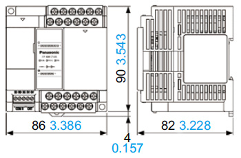
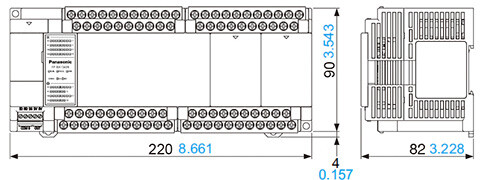
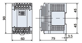
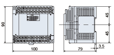
Dimensions
- Unit: mm in
Control Units
AFPXHC14□
AFPXHC30□

AFPXHC60□
Expansion Units
AFPX-EFP0(Expansion FP0 Adapter)
AFPX-E16□ / E14□
AFPX-E30□
------------------------------ Tab7 showing ------------------------------