Basic Information

New Multi-functional & Economical PLC


Features
Plenty of I/O points -150 points max. [L40□ / L60□]
If the customer can not predict the number of I/O points needed by his machineries and devices in the future, he will feel hesitant and uncomfortable. But, the I/O number of FP-X0 can reach 150 points max. by using the FP-X expansion unit. Therefore, the customer's discomfort and hesitation can be eliminated.
(L14R and L30R don't have the expansion function, so they can not be expanded.)
• The maximum number of expansion unit is up to 3 units.
![Plenty of I/O points -150 points max. [L40□ / L60□]](https://tp.industry.panasonic.com/hubfs/pid-corp/products/fasys/plc/plc/fp-x0/images/pic02.jpg)
![Plenty of I/O points -150 points max. [L40□ / L60□]](https://tp.industry.panasonic.com/hubfs/pid-corp/products/fasys/plc/plc/fp-x0/images/pic03.jpg)
The cable between the units can be bent to realizethe side-by-side installation, thus saving the installation space.
Further expansion and more functions achieved by using the existing FP0R expansion unit easily [L40□ / L60□]
The maximum number of FP0R expansion unit is up to 3 after the control units are equipped with adapters.
A wider range of application can be achieved by using [transistor output], [analog I/O], [thermocouple input] and [I/O LINK (network)].
Only one FP0 expansion adapter can be installed on the control unit.
In addition, two FP-X expansion units can be installed after the adapter is installed.
(L14R and L30R don't have the expansion function, so they can not be expanded.)
![Further expansion and more functions achieved by using the existing FP0R expansion unit easily [L40□ / L60□]](https://tp.industry.panasonic.com/hubfs/pid-corp/products/fasys/plc/plc/fp-x0/images/pic04.jpg)
Besides the supplied expansion cable of 8 cm3.150 in, 30 cm11.811 inand 80 cm31.496 intypes are also sold separately.They can be bent or straightened. (The total extension length is within 160 cm62.992 in.)
![Further expansion and more functions achieved by using the existing FP0R expansion unit easily [L40□ / L60□]](https://tp.industry.panasonic.com/hubfs/pid-corp/products/fasys/plc/plc/fp-x0/images/pic05.jpg)
Both of them are 90 mm3.543 inand can be installed in the cabinet.
Super-high processing speed
Super-high speed of 80 ns/step for 0 to 3,000 steps (ST command). 580 ns/step processing speed for 3,001 steps or more (Only for L40□ and L60□).
Body equipped with combined relay and transistor output
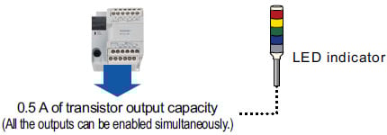
Pulse output function / High-speed counter function
The pulse output function of FP-X0 (1-axis for L14R and 2-axis for L30R / L40□ / L60□) is built in the body of the control unit.
Compared with the previous PLC that must use the advanced or specific positioning units or more than two multi-axis control devices, FP-X0 only uses one unit basically, thus saving the space and reducing the cost.
Built-in 4-point high-speed counter
4-point for 1-phase or 2-point for 2-phase (X0 to X3)
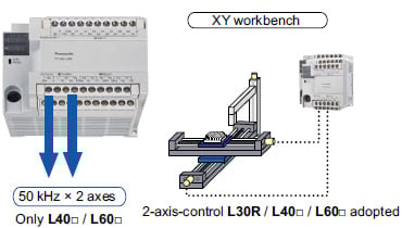
Adopting 2-axis linear interpolation [L40□ / L60□]
2-axis linear interpolation is a kind of function that controls 2 motor axes and makes the robot arm and tool head carry out diagonal line moving simultaneously, which is applied in the stacker’s picking & mounting components, the control of XY workbench and the baseplate cutting etc.
![Adopting 2-axis linear interpolation[L40□ / L60□]](https://tp.industry.panasonic.com/hubfs/pid-corp/products/fasys/plc/plc/fp-x0/images/pic09.jpg)
 |  |  |  |
| Product name | Power supply | Specifications | Part No. | |||
|---|---|---|---|---|---|---|
| Program capacity | Analog input | RS485 communication | ||||
| FP-X0 L14R | 100 - 240 V AC | 24 V DC input, 8 points 0.5 A/5 - 24 V DC transistor output, 2 points 2 A relay output, 4 points | 2.5 k steps | - | - | AFPX0L14R |
| FP-X0 L30R | 100 - 240 V AC | 24 V DC input, 16 points 0.5 A/5 - 24 V DC transistor output, 4 points 2 A relay output, 10 points | 2.5 k steps | - | - | AFPX0L30R |
| FP-X0 L40R | 100 - 240 V AC | 24 V DC input, 24 points 0.5 A/5 - 24 V DC transistor output, 4 points 2 A relay output, 12 points | 8 k steps | 10 bits, 2 channels | - | AFPX0L40R |
| FP-X0 L40MR | 100 - 240 V AC | 24 V DC input, 24 points 0.5 A/5 - 24 V DC transistor output, 4 points 2 A relay output, 12 points | 8 k steps | 10 bits, 2 channels | Available | AFPX0L40MR |
| FP-X0 L60R | 100 - 240 V AC | 24 V DC input, 32 points 0.5 A/5 - 24 V DC transistor output, 4 points 2 A relay output, 24 points | 8 k steps | 10 bits, 2 channels | - | AFPX0L60R |
| FP-X0 L60MR | 100 - 240 V AC | 24 V DC input, 32 points 0.5 A/5 - 24 V DC transistor output, 4 points 2 A relay output, 24 points | 8 k steps | 10 bits, 2 channels | Available | AFPX0L60MR |
Note) 24 V DC input: ± common
Expansion units [FP-X]


Input Unit / Output unit
| Product name | Power supply | Specifications | Part number |
|---|---|---|---|
| FP-X E16X Expansion Input Unit | - (Power is supplied from the left-side Unit.) | 24 V DC, 16 input points *1 | AFPX-E16X |
| FP-X E14YR Expansion Output Unit | - (Power is supplied from the left-side Unit.) | 2A relay, 14 output points *1 | AFPX-E14YR |
I/O Unit (Relay output)
| Product name | Power supply | Specifications | Part number |
|---|---|---|---|
| FP-X E16R Expansion I/O Unit | - (Power is supplied from the left-side Unit.) | 8-point input of 24 V DC, 8-point relay output of 2 A *1 | AFPX-E16R |
| FP-X E30R Expansion I/O Unit | 100~240V AC | 16-point input of 24 V DC, 14-point relay output of 2 A *2 | AFPX-E30R |
| FP-X E30RD Expansion I/O Unit | 24V DC | 16-point input of 24 V DC, 14-point relay output of 2 A *2 | AFPX-E30RD |
I/O Unit (Transistor output)
| Product name | Power supply | Specifications | Part number |
|---|---|---|---|
| FP-X E16T Expansion I/O Unit | - (Power is supplied from the left-side Unit.) | 8-point input of 24 V DC, 8-point transistor (NPN) output of 0.5 A *1 | AFPX-E16T |
| FP-X E16P Expansion I/O Unit | - (Power is supplied from the left-side Unit.) | 8-point input of 24 V DC, 8-point transistor (PNP) output of 0.5 A *1 | AFPX-E16P |
| FP-X E30TD Expansion I/O Unit | 24V DC | 16-point input of 24 V DC, 14-point transistor (NPN) output of 0.5 A *2 | AFPX-E30TD |
| FP-X E30T Expansion I/O Unit | 100~240V AC | 16-point input of 24 V DC, 14-point transistor (NPN) output of 0.5 A *2 | AFPX-E30T |
| FP-X E30PD Expansion I/O Unit | 24V DC | 16-point input of 24 V DC, 14-point transistor (PNP) output of 0.5 A *2 | AFPX-E30PD |
| FP-X E30P Expansion I/O Unit | 100~240V AC | 16-point input of 24 V DC, 14-point transistor (PNP) output of 0.5 A *2 | AFPX-E30P |
*1 Two or more E16T cannot be connected serially because it cannot supply the power to other units. With an 8cm extension cable
*2 Possible to connect up to 8 units including E16, EFP0. With an 8cm extension cable
*3 The 24 V DC inputs of all Units are bi-directional (sink/source) inputs.
[Units in common with FP0R]
Expansion units / Intelligent units / Link and Communication units
An expansion FP0 adapter is required for expanding the FP0R unit.
| Product name | Power supply | Specifications | Part No. |
|---|---|---|---|
| Expansion FP0 adapter | 24V DC | Up to 3 FP0R expansion Units can be connected via an adapter. With an 8cm extension cable and power cable. (Note) | AFPX-EFP0 |
(Note) : Only one unit can be installed in the control unit, and it is installed at the end of the expansion unit.
Other cables and maintenance parts
| Product name | Specifi cations | Part No. | |
|---|---|---|---|
| Backup battery | For data storage backup and calender/clock backup | AFP8801 | |
| FP-X expansion cable (Note) | 8cm 3.150 in | AFPX-EC08 | |
| 30cm 11.811 in | AFPX-EC30 | ||
| 80cm 31.496 in | AFPX-EC80 | ||
| Cable for FP and computer connection (M5 type) | 3 m 9.843 ft | Round D-SUB, 9-pin, L-shaped type | AFC8503 |
| Power cable for FP0 | For the adaptor for FP0 expansion, 1 m 3.281 ft long | AFP0581 | |
| Installation bracket for FP0 (Long-strip type) | For FP0 expansion unit, 10 pieces per package | AFP0803 | |
Note) The cables for expansion can be extended to 160 cm 62.992 in max.
Specifications
Performance specifications
| Items | Specifications | |||||||
|---|---|---|---|---|---|---|---|---|
| L14R | L30R | L40R | L40MR | L60R | L60MR | |||
| Controllable I/O points | Control unit | DC input 8 points, Relay output 4 points, Transistor output 2 points | DC input 16 points, Relay output 10 points, Transistor output 4 points | DC input 24 points, Relay output 12 points, Transistor output 4 points | DC input 32 points, Relay output 24 points, Transistor output 4 points | |||
| When using FP-X E16 expansion I/O units | - | - | 88 points max. (3 expansion units max.) | 108 points max. | ||||
| When using FP-X E30 expansion I/O units | - | - | 130 points max. (3 expansion units max.) | 150 points max. (3 expansion units max.) | ||||
| When using FP0R expansion units | - | - | 196 points max. (3 expansion units max.) | 216 points max. (3 expansion units max.) | ||||
| Programming method/Control method | Relay symbol/Cyclic operation | |||||||
| Program memory | Built-in Flash-ROM (Free of backup battery) | |||||||
| Program capacity | 2.5 k steps | 8 k steps | ||||||
| No of instruction | Basic commands | Approx. 114 kinds | ||||||
| High-level commands | Approx. 230 kinds | |||||||
| Processing speed | 0.08 µs/step for basic commands 0.32 µs for high-level commands (MV commands) | 3 k steps: 0.08 µs/step for basic commands, 0.32 µs for high-level commands(MV commands) After 3 k steps: 0.58 µs/step for basic commands, 1.62 µs for high-level commands(MV commands) | ||||||
| Basic time | 0.15 ms or less | 0.18 ms or less | 0.31 to 0.35 ms or less | 0.34 to 0.39 ms or less | ||||
| I/O refreshing + basic time | When using E16: 0.4 ms × No. of units When using E30: 0.5 ms × No. of units When using FP0 expansion adapters: 1.4 ms + the refreshing time of the FP0 expansion unit | |||||||
| Memory for processing | Relays | External input (X) (Note 1) | 960 points | 1760 points | ||||
| External output (Y) (Note 1) | 960 points | 1760 points | ||||||
| Internal relay (R) | 1008 points | 4096 points | ||||||
| Special internal relay (R) | 224 points | |||||||
| Timer・Counter (T/C) | 256 points (Note 2) | 1024 points (Note 2) | ||||||
| Timer: (1 ms, 10 ms, 100 ms, 1 s)× 32767, Counter: 1 to 32767 | ||||||||
| Link relay (L) | No | 2048 points | ||||||
| Memory area | Data register (DT) | 2500 words | 8192 words | |||||
| Special data register (DT) | 420 words | |||||||
| Link data register (LD) | No | 256 words | ||||||
| File registration (FL) | No | |||||||
| Index register (I) | 14 words (IO to ID) | |||||||
| Differential points | Equivalent to program capacity | |||||||
| Master control relay (MCR) | 32 points | 256 points | ||||||
| Label number (JP+LOOP) | 100 points | 256 points | ||||||
| No. of step programs | 128 (Engineering) | 1000 (Engineering) | ||||||
| No. of subroutines | 100 | 500 | ||||||
| No. of interrupt programs | Input: 8 programs, timing: 1 program | |||||||
| Sampling trace | No | Yes | ||||||
| Comments storage | All of the I/O comments,explanations and block comments can be saved.(Free of backup battery, 328 k bytes) | |||||||
| PLC link function | No | Yes | ||||||
| Constant scan | In unit of 0.5 ms: 0.5 ms to 600 ms | |||||||
| Password | Available (4 or 8 digits) | |||||||
| Upload protection | Available | |||||||
| Self-diagnosis function | Checks of the watchdog timer and the program syntax | |||||||
| Program editting during Run | Available (Capacity modified simultaneously: 128 steps) But comments cannot be modified during the process. | Available (Capacity modified simultaneously: 512 steps) But comments can be modified during the process. | ||||||
| Downloading during Run | Available | |||||||
| High-speed counter (Note 3,4) | Body input | 1-phase, 4-channel (20 kHz max.) and 2-phase, 2-channel (20 kHz max.) | 1-phase, 4-channel (50 kHz max.) and 2-phase, 2-channel (20 kHz max.) | |||||
| Pulse output/ PWM output (Note 3,4) | Body output | Pulse: 1-channel (20 kHz max.) PWM: 1-channel (1.6 kHz max.) | Pulse: 2-channel (20 kHz max.) PWM: 2-channel (1.6 kHz max.) | Pulse: 2-channel (50 kHz) PWM: 2-channel(3.0 kHz max.) | ||||
| Pulse catch input/ Interrupt program | 8 points (High-speed counting and interrupt input included) | |||||||
| Periodical interrupt | 0.5 ms unit: 0.5 ms to 1.5 sec., 10 ms unit: 10 ms to 30 sec. | |||||||
| Analog input | No | 2-channel (For inputting any of the following items in each channel) | ||||||
| Potentiometer input Min. resistance value of potentiometer: 5 kΩ 10-bit resolution (K0 to K1000) Accuracy ± 1.0% F.S.+ accuracy of external reistors | ||||||||
| Thermistor input For inputting the resistance value of the thermistor (Min. resistance value of external thermistors + external resistance value > 2 kΩ) 10-bit resolution (K0 to K1023) Accuracy ± 1.0% F.S.+ accuracy of external thermistors | ||||||||
| Voltage input Absolute max. input voltage: 10 V 10-bit resolution (K0 to K1023) Accuracy ± 2.5% F.S.(F.S. = 10 V) | ||||||||
| Calendar/clock | No | Yes | ||||||
| Flash ROM backup (Note 5) | Backup made according to commands of F12 and P13 | Data memory (2500 words) | Data memory (8192 words) | |||||
| Automatic backup when power OFF | Counter: 6 points (C250 to C255) Process value of the counter: 6 points (EV250 to EV255) Internal relays: 5 points (WR58 to WR62) Data memory: 300 words (DT2200 to DT2499) | Counter: 16 points (C1008 to C1023) Process value of the counter: 16 points (EV1008 to EV1023) Internal relays: 8 points (WR248 to WR255) Data memory: 302 words (DT7890 to DT8191) | ||||||
| Backup battery | No | Yes (Backup lasting for the whole process) | ||||||
| RS485 communication port | No | Yes | No | Yes | ||||
Notes:
1) The actual usable points depend on the combination of the hardware.
2) The points of the timer can be added as required.
3) The rated voltage is 24 V DC at +25 ℃+77℉. The frequency may fall according to the changes of the voltage, temperature and operating conditions.
4) The maximum frequency may vary with the difference of the operating method.
5) The allowable writing operation is within 10000 times. Areas to be held and not held can be specified using the system registers.
General specifications
| Items | Specifications | |
|---|---|---|
| CE marking directive compliance | Low Voltage Directive, EMC Directive, RoHS Directive | |
| Operating temperature | 0 to +55℃ +32 to +131℉ | |
| Storage temperature | -40 to +70℃−40 to +158℉ | |
| Operating humidity | 10 to 95% RH (at 25℃+77℉, no condensation) | |
| Storage humidity | 10 to 95% RH (at 25℃+77℉, no condensation) | |
| Withstand voltage (Note 1) (Note 2) | Input terminals ⇔ Relay output terminals | 2300 V AC, 1 minute |
| All of the transistor output terminals ⇔ All of the relay output terminals | ||
| All of the input terminals⇔ All of the power supply terminals and functional ground terminals | ||
| All of the relay output terminals ⇔ All of the power supply terminals and functional ground terminals | ||
| All of the transistor output terminals ⇔ All of the power supply terminals and functional ground terminals | ||
| Power supply terminals ⇔ Ground terminals | 1500 V AC,1 minute | |
| Input terminals ⇔ Transistor output terminals | 500 V AC,1 minute | |
| Insulation resistance (Note 1) | Input terminals ⇔ Output terminals | 100 MΩ min. (500 V DC insulation resistance meter) |
| All of the transistor output terminals ⇔ All of the relay output terminals | ||
| All of the input terminals ⇔ All of the power supply terminals and functional ground terminals | ||
| All of the output terminals ⇔ All of the power supply terminals and functional ground terminals | ||
| Power supply terminals ⇔ Ground terminals | ||
| Vibration resistance | 5 to 8.4 Hz, 3.5 mm 0.138 inamplititude in one direction, 1 scan/1 minute 8.4 to 150 Hz,fixed acceleration of 9.8 m/s2, 1 scan/1 minute 10 minutes in X,Y,Z direction each | |
| Shock resistance | 147 m/s2, 4 times in X, Y, Z directions each | |
| Noise immunity | 1500 V [p-p] pulse width 50 ns, 1 μs (Measured from nosie simulation method AC power supply termianls) | |
| Operating environment | No corrosive gases or too much dust | |
| Conformed EC Directives | EMC Directive: EN61131-2, Low Voltage Directive: EN61131-2 | |
| Overvoltage class | II | |
| Pollution level | 2 | |
| Weight | L14R: approx. 280g L30R: approx. 450g L40R/L40MR: approx. 530g L60R/L60MR: approx. 730g | |
Note 1) The programmable port, RS485 communication port and the internal digital circuit part are non-insulation type.
Note 2) The cut-off current is 5 mA (The default value when shipped from the factory).
Power supply specifications
· AC power supply
| Items | Specifications | |
|---|---|---|
| L14R | L30R, L40R, L40MR, L60R, L60MR | |
| Rated voltage | 100 to 240 V AC | |
| Applied voltage range | 85 to 264 V AC | |
| Inrush current | 35A max.(at 240 V AC and 25℃+77℉) | 40A max.(at 240 V AC and 25℃+77℉) |
| Momentary power off time | 10 ms (when 100 V AC used) | |
| Frequency | 50/60 Hz(47 to 63 Hz) | |
| Leakage current | 0.75 mA max.between the input and protectice ground terminals | |
| Service life of built-in power supply | 20000 h (at 55℃+131℉) | |
| Fuse | Built-in (replacement disabled) | |
| Insulation system | Transformer isolation | |
| Screw of terminal block | M3 | |
· Univeral power supply for intput (output) (L30/L40/L60 only)
| Items | Specifications |
|---|---|
| Rated output voltage | 24 V DC |
| Applied voltage range | 21.6 to 26.4 V DC |
| Rated output current | 0.3A |
| Overcurrent protection (Note) | Yes |
| Screw of terminal block | M3 |
Note) Output short protection is a temporary overcurrent protection. When the short is detected, all the power supplies of PLC will be turned OFF.
If the current load out of this specifi cation is connected and in consecutive over-loaded status, failures may occur.
Input specifications
| Items | Specifications | ||||||
|---|---|---|---|---|---|---|---|
| L14R | L30R | L40R | L40MR | L60R | L60MR | ||
| Insulation method | Optical coupler | ||||||
| Rated input voltage | 24 V DC | ||||||
| Applied voltage range | 21.6 V DC to 26.4 V DC | ||||||
| Rated input current | Approx. 3.5 mA (Control uint: X0 to X3); Approx. 4.3 mA (Control unit: X4 and the following ones) | ||||||
| Input points per common | 8 points/COM (L14R),16 points/COM (L30R), 24 points/COM (L40R),16 points/COM×2 (L60R) (Input power supply +/- are both available.) | ||||||
| Min. ON voltage/Min. ON current | 19.2 V DC/3 mA | ||||||
| Max. OFF voltage/Max. OFF current | 2.4 V DC/1.0 mA | ||||||
| Input impedance | Approx. 6.8 kΩ (Control units: X0 to X3), Approx.5.6 kΩ (control unit X4 and the following ones) | ||||||
| Response time | OFF→ON | For X0 to X3, 1 ms max.: common input 25 µs max.(Note): When setting high-speed counter, pulse catching input and interrupt input X4 and the following ones: 1 ms max. | For X0 to X3, 1 ms max.: common input 10 µs max.(Note): When setting high-speed counter, pulse catching input and interrupt input X4 and the following ones: 1 ms max. | ||||
| ON→OFF | Same as the above. | ||||||
| Action indicator | LED indication | ||||||
| EN61131-2 application type | TYPE 3 standard (Depending on the above-mentioned specifi cations) | ||||||
Note) The specifications mentioned above are at rated 24 V DC and operationg temperature of 25℃.
·Circuit diagram
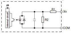
X0 to X3 : R1 = 6.8 kΩ, R2 = 820 ΩX4 and the following : R1 = 5.6 kΩ, R2 = 1 kΩ
Output specifications
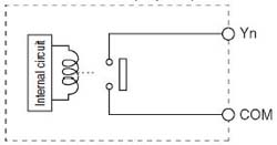
· Relay output specifictions
| Items | Specifications | ||||||
|---|---|---|---|---|---|---|---|
| L14R | L30R | L40R | L40MR | L60R | L60MR | ||
| Insulation method | Relay insulation | ||||||
| Output form | 1a output (Relay replacement disabled) | ||||||
| Rated control capacity (Resistance load) (Note) | 2A 250 V AC, 2A 30 V DC (per point) | ||||||
| Output points per common | 1 point/ COM×2 2 points/ COM×1 | 2 points/ COM×1 4 points/ COM×2 | 1 point/COM×2 2 points/COM×1 4 points/COM×2 | 4 points/COM×6 | |||
| Response time | OFF→ON | Approx. 10 ms | |||||
| ON→OFF | Approx. 8 ms | ||||||
| Life | Mechanical | 20000000 times min.(Switching frequency 180 times/minute) | |||||
| Electrical | 100000 times min. (Depending on the rated control capacity, switching frequency of 20 times/minute) | ||||||
| Surge absorber | No | ||||||
| Action indicator | LED indication | ||||||
Note) There are restrictions on the rated current for each output block. Each usable rated current is as below.
L14:Y2 to Y5(4 points) Max. 6A in total
L30:Y4 to YD(10 points) Max. 8A in total
L40:Y4 to YFD(12 points) Max. 8A in total
L60:Y4 to YB(8 points) Max. 8A in total,YC to Y1B(16 points) Max. 8A in total
·Circuit diagram
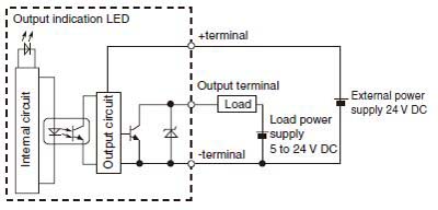
·Transistor (NPN) output specifications
| Items | Specifications | ||||||
|---|---|---|---|---|---|---|---|
| L14R | L30R | L40R | L40MR | L60R | L60MR | ||
| Insulation method | Optical coupler | ||||||
| Output method | Open-collector | ||||||
| Rated load voltage | 5 to 24 V DC | ||||||
| Allowable range of load voltage | 4.75 to 26.4 V DC | ||||||
| Max. load current | 0.5 A | ||||||
| Max. impact current | 1.5 A | ||||||
| Output points per common | 2 points/COM | 4 points/COM | |||||
| Leakage current at OFF status | 1 µA max. | ||||||
| Max. voltage drop at ON status | 0.3 V DC max. | ||||||
| Response time (at 25℃) | OFF→ON | 10 µs max. (Load current over 15 mA) | 5 µs max. (Load current over 15 mA) | ||||
| ON→OFF | 40 µs max. (Load current over 15 mA) | 15 µs max. (Load current over 15 mA) | |||||
| External power supply (Positive and negative teiminals) | Voltage | 21.6 to 26.4 V DC | |||||
| Current | 15 mA max. | ||||||
| Surge absorber | Zener diode | ||||||
| Action indicator | LED indication | ||||||
·Circuit diagram
[NPN output]
[Y0 to Y3]
Dimensions
Unit: mm inAFPX0L14R-F

AFPX0L30R-F

AFPX0L40R-F
AFPX0L40MR-F

AFPX0L60R-F
AFPX0L60MR-F
