------------------------------ Tab1 showing ------------------------------
Basic Information

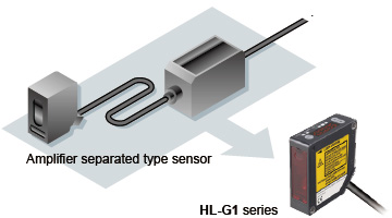
Introducing the new standard in CMOS laser displacement sensors


Features
This single instrument delivers both high-precision measurement and computer-driven data analysis
High resolution of 0.5 μm 0.020 mil
Thanks to high-precision measurement at a resolution of 0.5 μm 0.020 mil and an LED digital display that provides exceptional ease of use, the HL-G1 series will see use in a variety of applications on production lines worldwide.
Quick
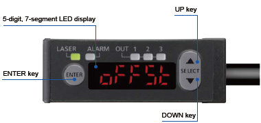
Setup is fast and efficient by using the built-in digital display to set measurement parameters such as sampling cycle and output options.
Compact
The HL-G1 series features a compact design despite its built-in controller and digital readout. Thanks to our miniaturization technology, it can easily be installed on robot arms and in confined spaces.
Friendly
The HL-G1 series now features a userfriendly interface that offers improved ease of use when operating via computer software or HMI unit for more sophisticated operation and analysis.
Easy input settings while looking at digital display
The built-in digital display makes it easy to perform sensor setting while checking displacement values.
Lightweight body that can be installed on movable parts
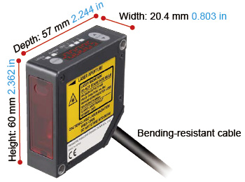
Its lightweight resin body weighs 70 g approx., which can be installed on moving parts such as sliders and robot arms. Cable with superior flexibility is fitted as standard.
Compact
Compact size despite the built-in controller and digital read out.
Easy to embed in machines and production lines
Controller installation and mounting space is not required because controller function is included in sensor unit.
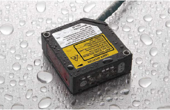
IP67 protective enclosure protects from water and dust
Thanks to its IP67 protective enclosure, the HL-G1 can be used in the presence of water and dust.
Mounting holes are lined with metal sleeves, allowing the instrument to be tightened securely in place with up to 0.8 N·m of torque.
Timing input and multi input
In addition to timing input select the desired input according to your application:
•Zero set on / off
•Laser control
•Reset
•Teaching
•Memory switching
•Saving
Featuring 3 outputs and an analog 2 outputs
With three outputs, the HL-G1 can be used to generate HI / GO / LOW judgment output or alarm output. The analog output can be used in both current and voltage modes.
Support for both NPN and PNP polarity [GLOBAL SUPPORT]
A single model number accommodates both NPN and PNP wiring polarity, reducing the number of model numbers that must be registered for maintenance purposes.
Featuring 3 outputs and an analog 2 outputs
With three outputs, the HL-G1 can be used to generate HI / GO / LOW judgment output or alarm output. The analog output can be used in both current and voltage modes.
Memory switching function
Up to four groups of sensor settings can be stored for fast recall. Easy switching among setting groups allows smooth setup changes.
HIGH FUNCTION TYPE (HL-G1□-S-J / HL-G1□-RS-J)
The integrated communications interface lets the sensor communicate with upstream devices such as PLCs.
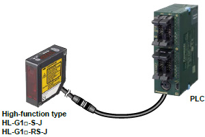
Sensors and other devices can be connected in a 1:1 manner using RS-422, or up to 16 HL-G1 series sensors can be connected using RS-485, enabling them to return measured values in response to messages from the PLC.
When using one of our PLCs*, you can use the PLC’s data write / read instructions (F145 and F146) to easily configure HL-G1 series settings and acquire measurement output.
* Supported PLCs from Panasonic Industry: FP0R, FPΣ, FP-X
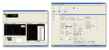
Software tool for sensor configuration and evaluation (Free download available)
In addition to configuring up to 16 sensors at once, this free tool makes it easy to gather data needed for analysis, such as received light waveform monitoring and data buffering. The interface language can be selected at the time of installation.
● Data buffering
Stores and displays measurement data, which can be superimposed on previously recorded data for easy comparison and analysis.
● Received light waveform display
Displays the amount of light received by cell from lightreceiving element.
● Measured value display
Displays measured values as well as the output state for each terminal.
HMI screen (Free download available)
The GT02 / GT12 series HMI can be used in combination with the HL-G1 to allow easy confirmation of sensor status and configuration of sensor settings from a remote location. Japanese, English, Chinese, and Korean are supported. For more information about the GT series, refer to the GT series pages.
* Orders for the GT02 / GT12 series will close on the following dates.
・Type with SD memory card slot: September 30, 2024
・Type without SD memory card slot: September 30, 2025

| Select from the following HMI operator panels: Power supply: 24 V Communications port: RS422 (RS485) ・AIG02GQ14D ・AIG02MQ15D ・AIG12GQ14D / AIG12GQ15D ・AIG12MQ14D / AIG12MQ15D |
・Measured value display
Displays measured values as well as the output state for all terminals.
| Operating environment | ||||
|---|---|---|---|---|
| PC environment | PC/AT compatible | |||
| OS | OS | 32/64 | Edition | Service Pack |
| Windows® 7 | 32bit/64bit | Professional | - | |
| Windows® 8.1 | Pro | |||
| Windows® 10 | ||||
| CPU | 2 GHz or more | |||
| Graphics | SXGA (1280 x 1024 full colors) or more | |||
| Memory | 2 GB or more | |||
| Hard disk | Free space 100 MB or more | |||
| USB interface | USB 2.0 full speed (USB 1.1 compatible) | |||
*Windows® 10 Pro, 8.1 Pro and 7 Professional are trademarks or registered trademarks of Microsoft Corporation in the United State and other countries.
* This software accommdates below language. You can select the language when installing.
・Japanese ・English ・Korean ・Chinese
Multilingualization [GLOBAL SUPPORT]
Software tool and HMI screen data support not only Japanese and English, but also Chinese and Korean, providing a new level of support for devices and equipment in use worldwide.
■ Software Download
Sensor configuration and evaluation software tool, HMI screen data, function blocks, etc.
*Membership registration is required to access/download this data.
>>Go to Data download.
------------------------------ Tab2 showing ------------------------------


------------------------------ Tab3 showing ------------------------------
Order guide
Sensor Heads
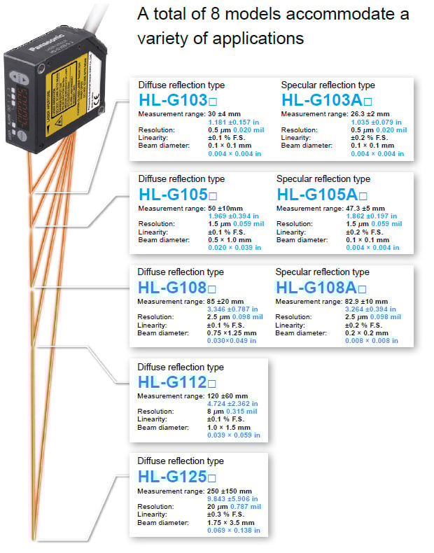
Diffuse reflection type
| Type | Appearance | Measurement center distance and measuring range | Resolution | Beam diameter | Model No. |
|---|---|---|---|---|---|
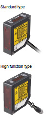
| Standard type |
| 30 ±4 mm 1.181 ±0.157 in | 0.5 μm 0.020 mil | 0.1 × 0.1 mm 0.004 × 0.004 in | HL-G103-A-C5 |
| High function type | HL-G103-S-J | ||||
| Standard type | 50 ±10 mm 1.969 ±0.394 in | 1.5 μm 0.059 mil | 0.5 × 1.0 mm 0.020 × 0.039 in | HL-G105-A-C5 | |
| High function type | HL-G105-S-J | ||||
| Standard type | 85 ±20 mm 3.346 ±0.787 in | 2.5 μm 0.098 mil | 0.75 × 1.25 mm 0.030 × 0.049 in | HL-G108-A-C5 | |
| High function type | HL-G108-S-J | ||||
| Standard type | 120 ±60 mm 4.724 ±2.362 in | 8 μm 0.315 mil | 1.0 × 1.5 mm 0.039 × 0.059 in | HL-G112-A-C5 | |
| High function type | HL-G112-S-J | ||||
| Standard type | 250 ±150 mm 9.843 ±5.906 in | 20 μm 0.787 mil | 1.75 × 3.5 mm 0.069×0.138 in | HL-G125-A-C5 | |
| High function type | HL-G125-S-J |
Specular reflection type
| Type | Appearance | Measurement center distance and measuring range | Resolution | Beam diameter | Model No. |
|---|---|---|---|---|---|
| Standard type |
| 26.3 ±2 mm 1.035 ±0.079 in | 0.5 μm 0.020 mil | 0.1 × 0.1 mm 0.004 × 0.004 in | HL-G103A-RA-C5 |
| High function type | HL-G103A-RS-J | ||||
| Standard type | 47.3 ±5 mm 1.862 ±0.197 in | 1.5 μm 0.059 mil | HL-G105A-RA-C5 | ||
| High function type | HL-G105A-RS-J | ||||
| Standard type | 82.9 ±10 mm 3.264 ±0.394 in | 2.5 μm 0.098 mil | 0.2 × 0.2 mm 0.008 × 0.008 in | HL-G108A-RA-C5 | |
| High function type | HL-G108A-RS-J |
Extension cable (For high function type)
| Type | Appearance | Model No. | Description | |
|---|---|---|---|---|
| Extension cable (for High function type) |
| HL-G1CCJ2 | Length: 2 m 6.562 ft, Weight: 130 g approx. | 14-core cabtyre cable with connector on both ends |
| HL-G1CCJ5 | Length: 5 m 16.404 ft, Weight: 320 g approx. | |||
| HL-G1CCJ10 | Length: 10 m 32.808 ft, Weight: 630 g approx. | |||
| HL-G1CCJ20 | Length: 20 m 65.617 ft, Weight: 1300 g approx. | |||

INFORMATION OF INTERFACE CONVERTER
The communications interface converter of HL-G1 series is RS-422 or RS-485. We will recommend the following interface converter when connecting to PC by USB.
| LINEEYE CO., LTD. Interface converter (USB to RS-422/485) SI-35USB Website:https://www.lineeye.com |
------------------------------ Tab4 showing ------------------------------
------------------------------ Tab5 showing ------------------------------
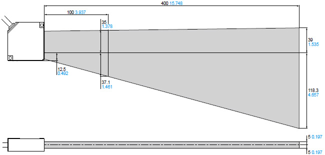
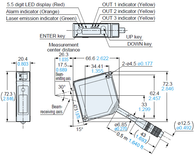
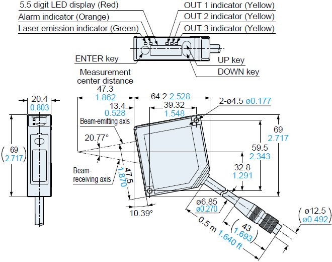
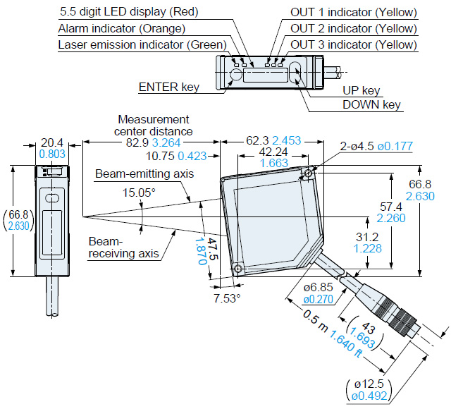
Dimensions
- Unit: mm in
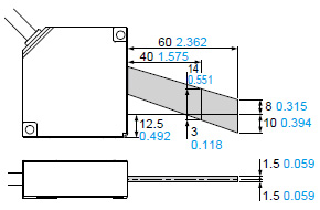
HL-G1□-A-C5
Sensor (Diffuse reflection / Standard type)
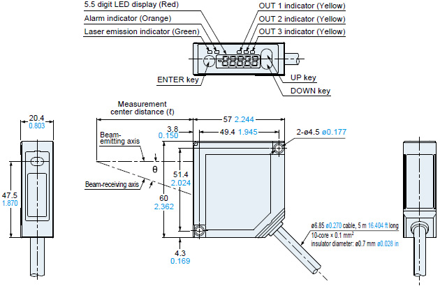
| Model No. | Measurement center distance (ℓ) | θ |
|---|---|---|
| HL-G103-A-C5 | 30 mm 1.181 in | 30° |
| HL-G105-A-C5 | 50 mm 1.969 in | 21° |
| HL-G108-A-C5 | 85 mm 3.346 in | 15° |
| HL-G112-A-C5 | 120 mm 4.724 in | 11° |
| HL-G125-A-C5 | 250 mm 9.843 in | 6.2° |
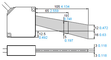
HL-G1□-S-J
Sensor (Diffuse reflection / High function type)
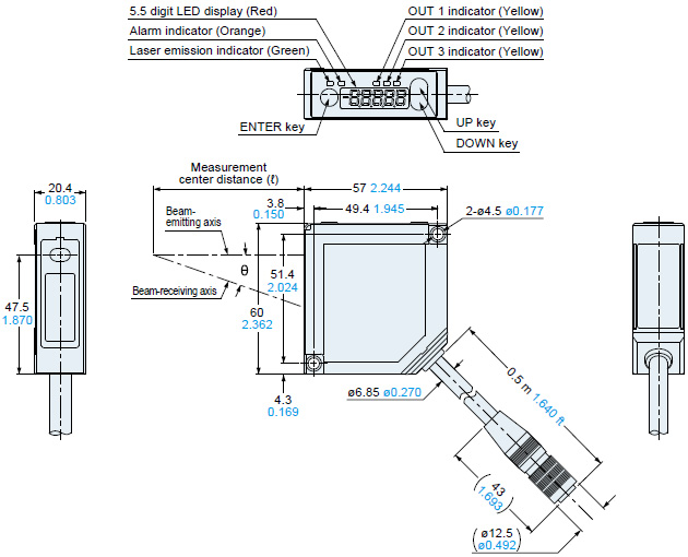
| Model No. | Measurement center distance (ℓ) | θ |
|---|---|---|
| HL-G103-S-J | 30 mm 1.181 in | 30° |
| HL-G105-S-J | 50 mm 1.969 in | 21° |
| HL-G108-S-J | 85 mm 3.346 in | 15° |
| HL-G112-S-J | 120 mm 4.724 in | 11° |
| HL-G125-S-J | 250 mm 9.843 in | 6.2° |
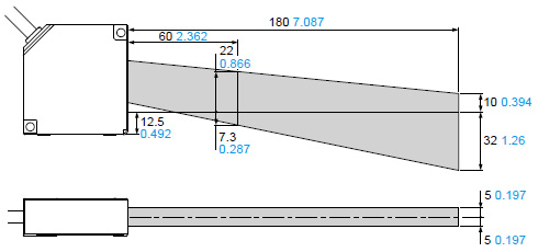
HL-G1CCJ□
Extension cable (Optional)
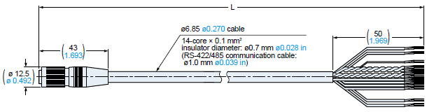
| Model No. | Measurement center distance (ℓ) |
|---|---|
| HL-G1CCJ2 | 2,000+200078.740+7.8740 |
| HL-G1CCJ5 | 5,000+5000196.850+19.6850 |
| HL-G1CCJ10 | 10,000+10000393.701+39.3700 |
| HL-G1CCJ20 | 20,000+20000787.402+78.7400 |
HL-G103A-RA-C5
Sensor (Specular reflection / Standard type)

HL-G103A-RS-J
HL-G105A-RA-C5
Sensor (Specular reflection / Standard type)
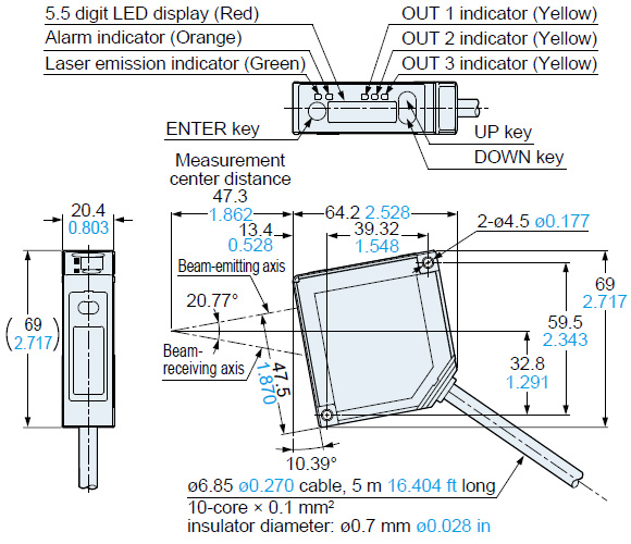
HL-G105A-RS-J
Sensor (Specular reflection / High function type)
HL-G108A-RA-C5
Sensor (Specular reflection / Standard type)
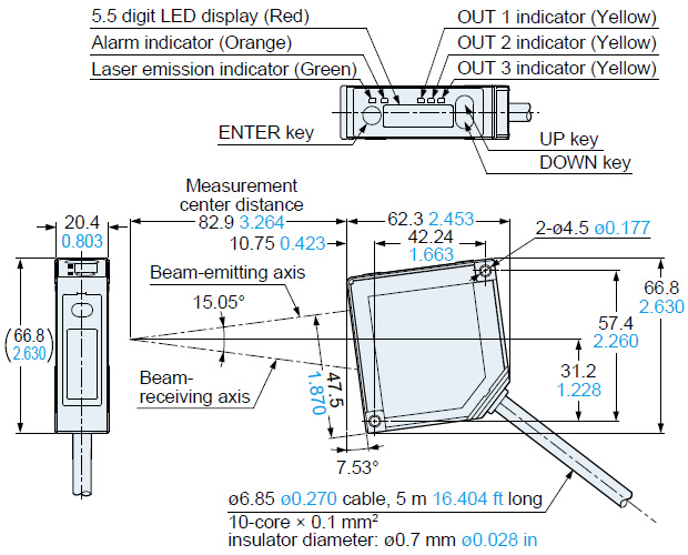
HL-G108A-RS-J
Sensor (Specular reflection / High function type)
------------------------------ Tab6 showing ------------------------------
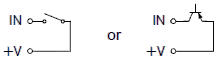
I/O Circuit and Wiring diagrams
I/O circuit diagrams
When selecting NPN output

*1 Non-voltage contact

When selecting PNP output

*1 Non-voltage contact or PNP open-collector transistor output
High [+5 V to +30 V DC (source current 0.04 mA or less)] : Effective
Low (0 to 0.6 V DC or open) : Ineffective
Analog output (common in NPN output type and PNP output type)
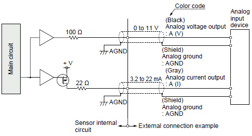
Notes:
1) Analog output is not equipped with the short-circuit protection. Do not short-circuit or apply voltage to them.
2) Use shielded wires for analog outputs.
Communication specifications (High function type)
| Communication method | RS-422 | RS-485 |
|---|---|---|
| Full duplex | Half duplex | |
| Synchronization method | Asynchronous communication method | |
| Transmission code | ASC ll | |
| Baud rate | 9,600/19,200/38,400/115,200/230,400/460,800/921,600 bps | |
| Data length | 8 bits | |
| Stop bit length | 1 bit | |
| Parity check | None | |
| BCC | Yes | |
| Termination code | CR | |
The HL-G1 can be connected to upper devices of RS-422/485.
When upper device sends the request command, the HL-G1 series send the response command.
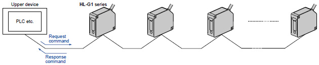
RS-422 1-to-1 connection
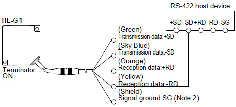
Notes:
1) The transmission data cable and reception data cable are both twisted-pair cables.
2) The shield is connected to the 0 V side of the power supply line inside the sensor.
3) Be sure to connect the signal ground.
4) The sensor is of non-isolated type. Make sure that the potential difference between the sensor and RS-422 connecting device does not exceed 4V. A difference in potential in excess may cause the connecting device or the sensor to malfunction.
RS-485 1-to-N connection
- Connectable up to 16 units.
- Please set the prefix with no duplication.
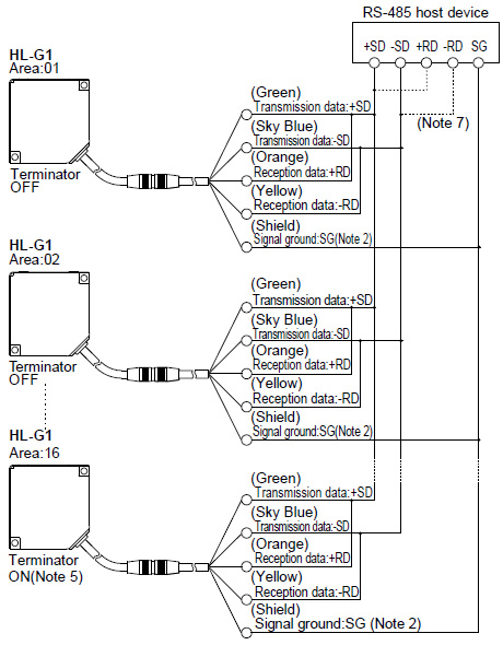
Notes:
1) The transmission data cable and reception data cable are both twisted-pair cables.
2) The shield is connected to the 0-V side of the power supply line inside the sensor.
3) Be sure to connect the signal ground.
4) The sensor is of non-isolated type. Make sure that the potential difference between the sensor and RS-485 connecting device does not exceed 4V. A difference in potential in excess may cause the connecting device or the sensor to malfunction.
5) The sensor has a built-in terminating resistor. Be sure to turn ON the terminating resistor of the terminating sensor.
6) Perform transition wiring for the transmission path.
7) Connect the wires according to the specification of the equipment.
------------------------------ Tab7 showing ------------------------------
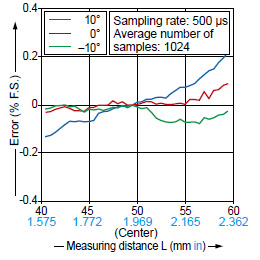
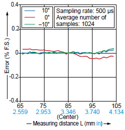
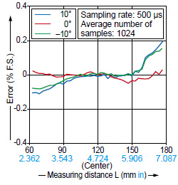
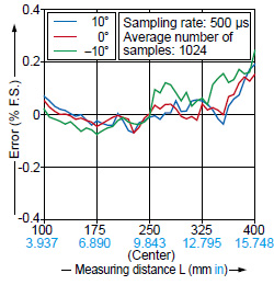
Sensing characteristics
TYPICAL
Correlation between measuring distance and error characteristics
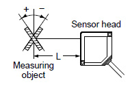
Diffuse reflection type
White ceramicVertical orientation

Horizontal orientation
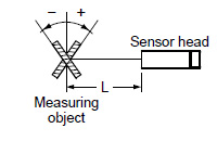
Specular reflection type
Alminum vapor depositionsurface reflection mirror
Vertical orientation
surface reflection mirror
Horizontal orientation
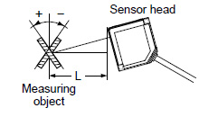
HL-G103□
Diffuse reflection type
Vertical positioning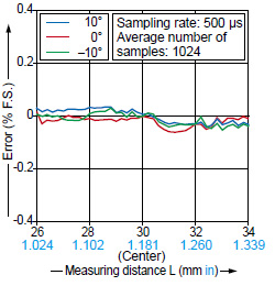
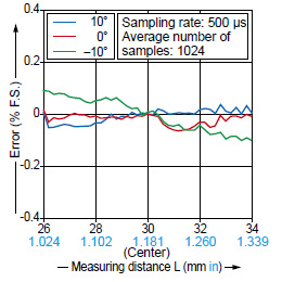
HL-G105□
Diffuse reflection type
Vertical positioning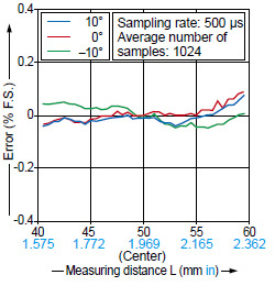
HL-G108□
Diffuse reflection type
Vertical positioning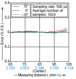
HL-G112□
Diffuse reflection type
Vertical positioning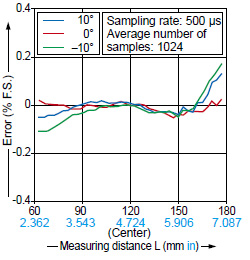
HL-G125□
Diffuse reflection type
Vertical positioning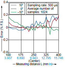
HL-G103A□
Specular reflection type
Vertical positioning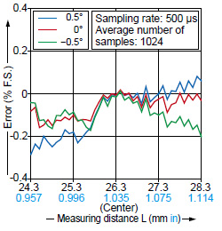
HL-G105A□
Specular reflection type
Vertical positioning
HL-G108A□
Specular reflection type
Vertical positioning
------------------------------ Tab8 showing ------------------------------
- [HL-G1□-S-J/HL-G1□-A-C5]
- This product is a class 2 laser product according to IEC/EN/JIS/GB/KS standards and FDA regulations.
- Avoid observing beams continuously, particularly in a dark surrounding environment.
- Do not look at beams using an optical device such as an optical telephoto system.
- Never attempt to disassemble, repair, or modify this product.
- A warning label according to IEC (EN) standards is affixed to this product, and warning labels according to JIS, GB, and KS standards are included with it. Remove the IEC (EN) warning label, and then affix an appropriate label to the product as needed.
- When exporting this product to the United States of America attach the FDA certificate / identification label to the cable close to the sensing device.

- [HL-G1□A-RS-J/HL-G1□A-RA-C5]
- This product is a class 1 laser product according to IEC/EN/JIS/GB/KS standards and FDA regulations*.
- Avoid observing beams in a dark surrounding environment.
- Do not look at beams using an optical device such as an optical telephoto system.
- Never attempt to disassemble, repair, or modify this product.
- The following label is affixed to this product. Handle the product according to the instruction given on the label.

*This product complies with the FDA regulations (FDA 21 CFR 1040.10 and 1040.11) in accordance with FDA Laser Notice No. 56, except for complying with IEC 60825-1 Ed. 3.
Safety standards for laser beam products
IEC : IEC 60825-1:2014
EN : EN 60825-1:2014/A11:2021
JIS : JIS C 6802:2014
GB : GB 7247.1-2012
KS : KS C IEC 60825-1:2014
FDA : PART 1040.10, 1040.11(Laser Notice No.56 applied)
Based on the above standards, the HL-G1 series are classified as Class 1/2 laser products.
| Class | Model | Description of hazardous evaluation |
|---|---|---|
| Class 1 | HL-G1□A-RA-C5 HL-G1□A-RS-J | Safe under reasonably foreseeable conditions. |
| Class 2 | HL-G1□-A-C5 HL-G1□-S-J | Visible beam, low power. Blink response of eye affords protection. |
Note: When an unexpected failure occurs, dangerous radiation may be generated. Therefore, pay special attention to safety.
- For the purpose of preventing any injury which may occur to the user by the use of the laser product in advance, the following standards have been established by the IEC Standards, EN Standards, JIS Standards, GB Standards, KS Standards and FDA Regulations.
- Classification according to IEC 60825-1:2014(JIS C 6802:2014)
Safe use of laser products
- For the purpose of preventing users from suffering injuries by laser products, each standard stipulates (Safety of laser products). Kindly check the standards before use.
Beam diameter
(Unit: mm in)
| Model No. | Beam diameter | |||||
|---|---|---|---|---|---|---|
| a | b | c | d | e | f | |
| HL-G103-S-J HL-G103-A-C5 | 0.15 0.006 | 0.15 0.006 | 0.1 0.004 | 0.1 0.004 | 0.15 0.006 | 0.15 0.006 |
| HL-G105-S-J HL-G105-A-C5 | 1.2 0.047 | 0.6 0.024 | 1.0 0.039 | 0.5 0.020 | 0.9 0.035 | 0.4 0.016 |
| HL-G108-S-J HL-G108-A-C5 | 1.5 0.059 | 0.9 0.030 | 1.25 0.049 | 0.75 0.030 | 1.0 0.039 | 0.6 0.024 |
| HL-G112-S-J HL-G112-A-C5 | 1.8 0.071 | 1.2 0.047 | 1.5 0.059 | 1.0 0.039 | 0.8 0.031 | 0.5 0.020 |
| HL-G125-S-J HL-G125-A-C5 | 2.5 0.098 | 1.5 0.059 | 3.5 0.138 | 1.75 0.069 | 4.5 0.177 | 2.0 0.079 |
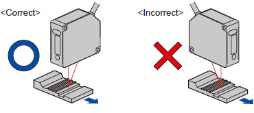
Sensor head mounting direction
Object with variations in material or color
- To obtain the greatest precision, the sensor head should be oriented facing the direction of movement of the object's surface, as shown in the figure below.
Rotating object
Object that has large differences in gaps, grooves and colors
Mutual interference
(Unit: mm in)
HL-G103□

HL-G105□
HL-G108□
HL-G112□
HL-G125□