------------------------------ Tab1 showing ------------------------------
Basic Information
High-speed sampling and high resolution.
The new choice for even more varied data collection and processing.


Korean KC : GP-XC□(-P) only
Features
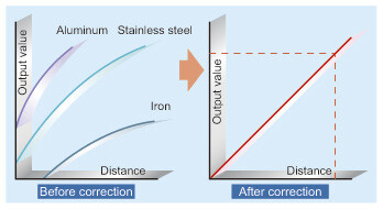
They perform with a ±0.3 % F.S. linearity for stainless steel and iron
Because they perform with a ±0.3 % F.S.
linearity, they can be used for sensing stainless steel and iron enabling precise measurements not affected by the work’s material. Specifications corresponding to each material (stainless steel, iron, aluminum) has already been inputted in the controller enabling the easy selection of the setting that is the most suitable for the particular material used.
We’ve realized a 25 μs (40,000 times/sec.) ultra high sampling speed
With a 25 μs ultra high sampling speed, the GP-X series will not miss even high speed work displacements.
These devices boast a 0.07 % F.S./°C temperature characteristics
By combining the sensor head with the controller, we have achieved 0.07 % F.S./℃. Highly resistant to ambient temperature changes enabling stable microdisplacement measurements.
They possess a 0.02 % F.S. resolution for highly accurate measurement
With high resolution, 0.02 % F.S. (Note), they can perform high-accuracy measurements of microdisplacements.
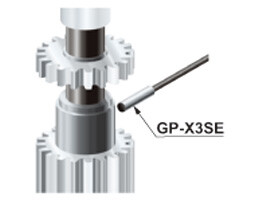
In particular, the sensor head GP-X3SE for 0.8 mm 0.049 in sensing can differentiate ultra microdisplacement of 0.32 μm 0.013 mil (Average number of samples: 64).

Note:GP-XC3SE and GP-XC5SEResolution: 0.04 % F.S.
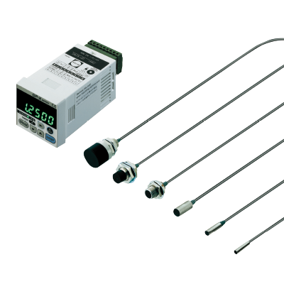
IP67G sensor head variation
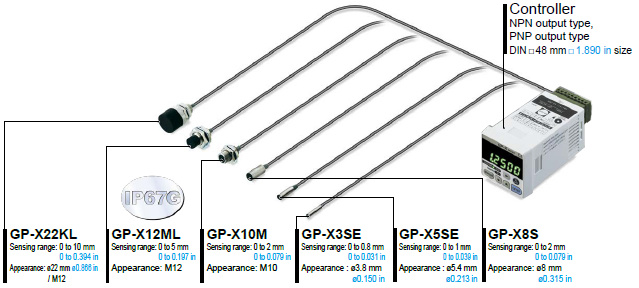
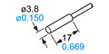
6 types of sensor heads from the ultra compact ø3.8 mm ø0.150 in cylindrical type to the long range sensing type ø22 mm ø0.866 in are available.
All sensor heads are oil-proof as per IP67G enabling safe, stable performance.
* Please check the resistivity of the sensor against the cutting oil you are using beforehand.
Sensor heads with superior workability and mainfainability

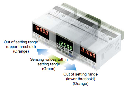
The 5-digit, dual, 2-color digital display offers great visibility
If the measurement results fall within the setting range (GO), they will appear on the lower digital display in green.
If they are out of range (HI, LO), they will be displayed in the upper digital display in orange. The display position and color change allows for accurate visibility even for momentary changes.
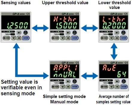
Digital input display enabling easy setting
Its dual digital display enables numerical setting while verifying setting items for each mode. Even in sensing mode, it enables the verification of the main settings.
The RS-232C communication connector is standard equipment
Capable of various controls such as saving measurement data to PC and the controller's inputted settings and loading stored memory.

Enables sensors data comparisons and calculations
It is possible to calculate addition and subtraction of measured data between two inter-connected controllers, as well as to perform 3-value judgment output according to the calculation results. Digital panel controllers are not required because the calculation function is incorporated.
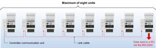
Datalink between sensors is possible
The controller communication unit GP-XCOM (optional) can be linked to up to 8 controllers and load each controller settings and measurement data to a PC via just one RS-232C cable.
An intelligent monitor (GP-XAiM) optimal for collecting and analyzing measurement data is also available
An intelligent monitor capable of setting each measurement conditions and monitoring waveform display. It can easily perform waveform monitoring, which could until now only be done by the oscilloscope, as well as loading and saving of settings for each condition and function onto a PC.
BCD output unit GP-XBCD (Optional)
・20 kHz high-speed data output
The measurement data can be processed quickly in the PLC. (Sampling rate: 20 kHz)

* When using the BCD output unit GP-XBCD, the analog voltage output of a controller becomes invalid.
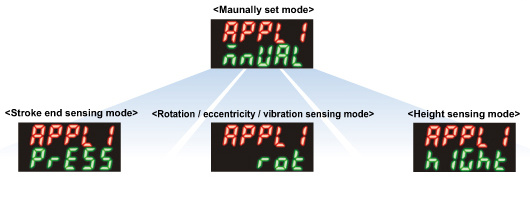
・4 types of measurement modes available
Measurement modes compatible to the most widely used applications are available. Because of this, inputting setting values can be done with ease. Please select the most appropriate mode to suit your specific application.
・Mutual interference prevention function
Interference of sensor heads can be prevented by shifting the oscillation timing while connecting controllers of maximum 8 units with the interference prevention output line. Precise measurement can be achieved even in cases where many sensor heads are used in a narrow area.
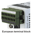
・Removable type terminal block
It is equipped with a removable type European terminal block very convenient during assembly, when dividing the equipment into segments or when performing maintenance. It also features an reverse insertion prevention construction.
・4 types of selectable memory functions
The setting data can be processed in 4 types of memory when measuring. This function enables either the changing of the workpiece, the sensing of multiple products or sensing after product changeover to be done smoothly.
------------------------------ Tab2 showing ------------------------------
Stroke end sensing
------------------------------ Tab3 showing ------------------------------
Order guide
Non-threaded type sensor head
| Appearance (mm in) | Sensing range | Set model No. (Sensor head model No.) | Comparative output | |
|---|---|---|---|---|
| Sensor heads | Controller | |||
|
| 0 to 0.8 mm 0 to 0.031 in | GP-XC3SE (GP-X3SE) | NPN open-collector transistor |
| GP-XC3SE-P (GP-X3SE) | PNP open-collector transistor | |||
| 0 to 1mm 0 to 0.039 in | GP-XC5SE (GP-X5SE) | NPN open-collector transistor | |
| GP-XC5SE-P (GP-X5SE) | PNP open-collector transistor | |||
| 0 to 2mm 0 to 0.079 in | GP-XC8S (GP-X8S) | NPN open-collector transistor | |
| GP-XC8S-P (GP-X8S) | PNP open-collector transistor | |||
Threaded type sensor head
| Appearance (mm in) | Sensing range | Set model No. (Sensor head model No.) | Comparative output | |
|---|---|---|---|---|
| Sensor heads | Controller | |||
|
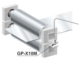
| 0 to 2mm 0 to 0.079 in | GP-XC10M (GP-X10M) | NPN open-collector transistor |
| GP-XC10M-P (GP-X10M) | PNP open-collector transistor | |||
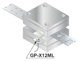
| 0 to 5mm 0 to 0.197 in | GP-XC12ML (GP-X12ML) | NPN open-collector transistor | |
| GP-XC12ML-P (GP-X12ML) | PNP open-collector transistor | |||
| 0 to 10mm 0 to 0.394 in | GP-XC22KL (GP-X22KL) | NPN open-collector transistor | |
| GP-XC22KL-P (GP-X22KL) | PNP open-collector transistor | |||
・The controller is not available for sale by itself.
・Sensor heads can only be replaced with the sensor heads with the same set model name. Different sensor heads cannot be used.
------------------------------ Tab4 showing ------------------------------
Option
| Designation | Model No. | Description | |
|---|---|---|---|
| BCD output unit | GP-XBCD | This unit outputs measurement values in BCD data format at a high speed. ・Sampling frequency: 20 kHz | |
| Cable with connector on one end for BCD output unit | GP-XBCC3 | Length: 3 m 9.843 ft | Cable for BCD data output unit ・26-core cable with connector on one end |
| Controller communication unit | GP-XCOM | Up to 8 controllers can be linked | |
| Link cable for controller communication unit | SL-F150 | Length: 150 mm 5.906 in | This cable links the controller communication units. Select as per the cable length. |
| SL-F250 | Length: 250 mm 9.843 in | ||
| SL-F1000 | Length: 1,000 mm 39.370 in | ||
| Extension cable for sensor head | GP-XCCJ7 | Length: 7 m 22.966 ft | This cable with connector is for extensions between the sensor head and controller. |
| Sensor head mounting bracket | MS-SS3 | Mounting bracket for GP-X3SE | |
| MS-SS5 | Mounting bracket for GP-X5SE | ||
| MS-SS8 | Mounting bracket for GP-X8S | ||
| Serial Cable | ANM81103 | COM port and PC (D-SUB : 9 pin) connection | |
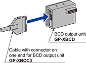
BCD output unit Cable with connector on one end for BCD output unit
GP-XBCD
GP-XBCC3
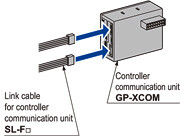
Controller communication unit Link cable for controller communication unit
GP-XCOM
SL-F□
Extension cable for sensor head
GP-XCCJ7

Sensor head mounting bracket
MS-SS□
The sensor head can be easily fixed.
------------------------------ Tab5 showing ------------------------------
------------------------------ Tab6 showing ------------------------------
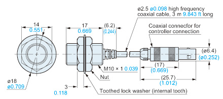
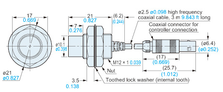
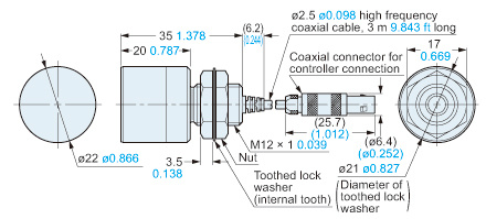
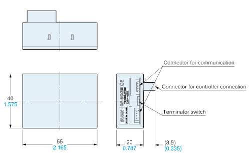
Dimensions
- Unit: mm in
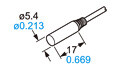
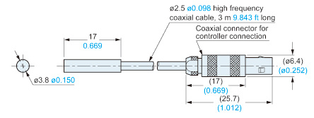
GP-X3SE
Sensor head
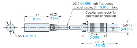
GP-X5SE
Sensor head
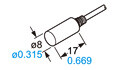
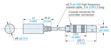
GP-X8S
Sensor head
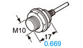
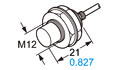
GP-X10M
Sensor head
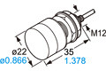
GP-X12ML
Sensor head
GP-X22KL
Sensor head
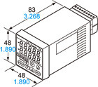
Controller
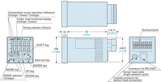
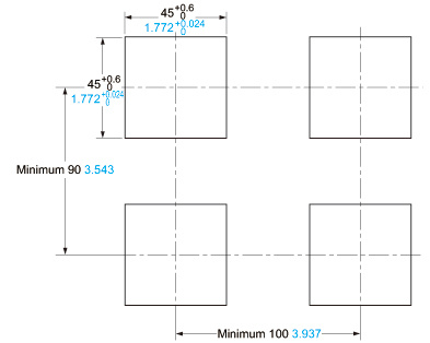
Panel cut-out dimensions
<When BCD output unit / controller communication unit not mounted>
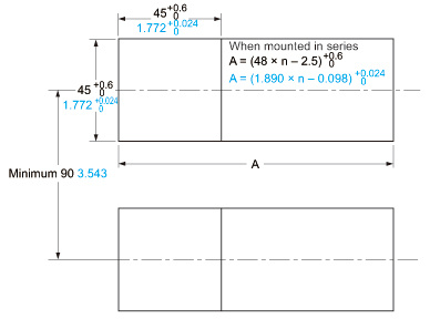
Note:The panel thickness should be 1 to 5 mm 0.039 to0.197 in.
<When BCD output unit / controller communication unit mounted>
Note:The panel thickness should be 1 to 2.5 mm 0.039 to0.098 in.
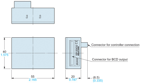
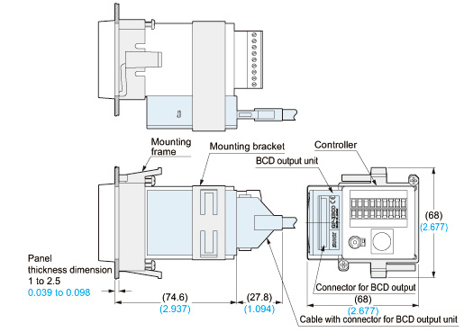
GP-XBCD
BCD output unit (Optional)
Assembly dimensions with controller
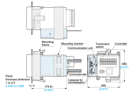
GP-XCOM
Controller communication unit (Optional)
Assembly dimensions with controller
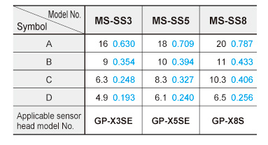
MS-SS3 MS-SS5 MS-SS8
Sensor head mounting bracket (Optional)
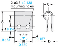
Material:Nylon 66
------------------------------ Tab7 showing ------------------------------
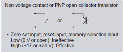
I/O Circuit and Wiring diagrams
NPN output type controller
I/O circuit diagram
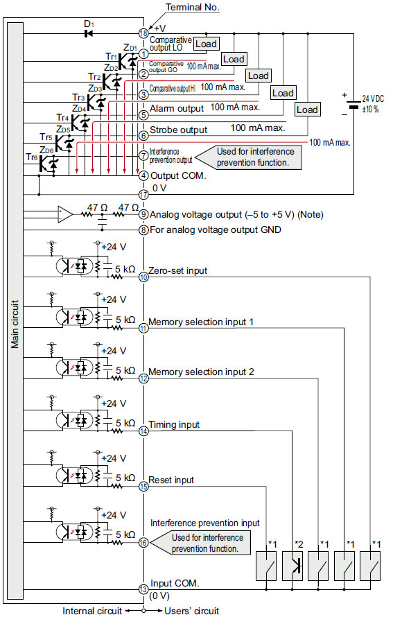
Note:
Devices connected to the analog voltage output must have an input impedance set at 1 MΩ or more.
Symbols・・・
D1: Reverse supply polarity protection diode
ZD1 to ZD6: Surge absorption zener diode
Tr1 to Tr6: NPN output transistor
*1
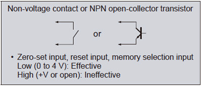
*2
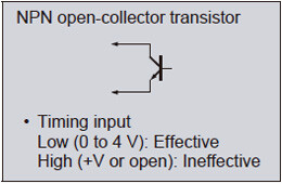
Memory selection input
| Memory No. | Memory selection 1 | Memory selection 2 |
|---|---|---|
| 0 | High | High |
| 1 | Low | High |
| 2 | High | Low |
| 3 | Low | Low |
PNP output type controller
I/O circuit diagram
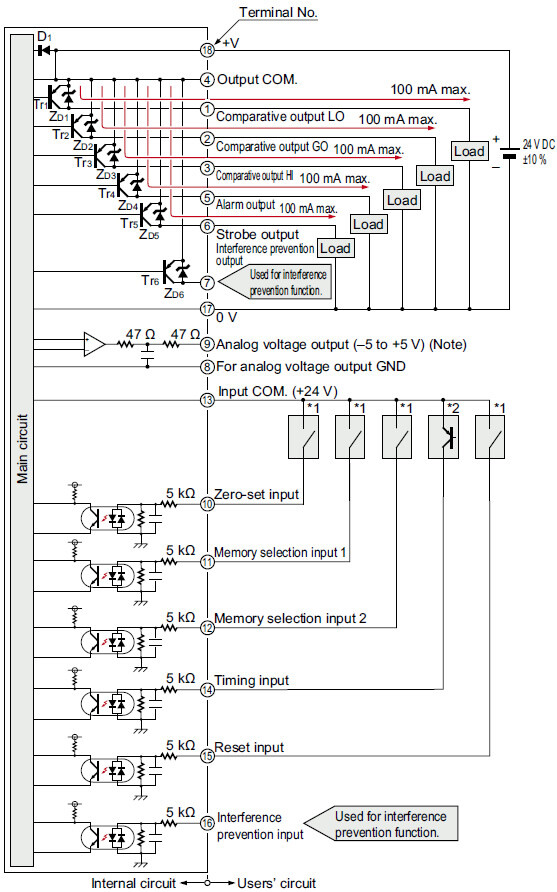
Note:
Devices connected to the analog voltage output must have an input impedance set at 1 MΩ or more.
Symbols・・・
D1: Reverse supply polarity protection diode
ZD1 to ZD6: Surge absorption zener diode
Tr1 to Tr6: PNP output transistor
*1
*2
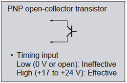
Memory selection input
| Memory No. | Memory selection 1 | Memory selection 2 |
|---|---|---|
| 0 | Low | Low |
| 1 | High | Low |
| 2 | Low | High |
| 3 | High | High |
------------------------------ Tab8 showing ------------------------------
・The sensor head and the controller are adjusted in order to conform to the default specification linearity.
・In the event of replacing sensor heads, input the sensor head’s characteristic code and conduct 3-point correction (calibration).
・Should you use an extension cable, turn the sensor head cable length selection switch located on the back of the controller to “3 m + 7 m 9.843 ft + 22.966 ft”. Then reintroduce the power supply and conduct 3-point correction (calibration).
Conditions in use for CE/UKCA conformity
Conditions
- This product is CE/UKCA compliant and complies with EMC directives/EMC regulations. EN 61000-6-2 is the applicable standard that covers immunities relating to use of this product, but in order to comply with this standard, the following conditions must be satisfied.
- The controller should be connected less than 10 m 32.808 ft from the power supply.
- The signal line to connect with the controller should be less than 30 m 98.425 ft.
- A ferrite clamp must be mounted within 10 mm 0.394 in from connector fitted onto the GP-XBCC3 cable with connector on one end for BCD output units.
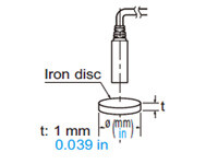
Linearity in case of disc-shaped or cylindrical objects
<In case of disc>
<In case of cylinder>
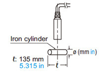
| Sensor head | Disc diameter ø (mm in) | Cylinder diameter ø (mm in) |
|---|---|---|
| GP-X3SE | 6 0.236 | 16 0.630 |
| GP-X5SE | 8 0.315 | 16 0.630 |
| GP-X8S | 12 0.472 | 50 1.969 |
| GP-X10M | 12 0.472 | 50 1.969 |
| GP-X12ML | 25 0.984 | 55 2.165 |
| GP-X22KLM | 30 1.181 | 165 6.496 |
- In case the sensing object is disc-shaped or cylindrical, the linearity varies with the sensing object size.
In the event the sensing object is larger than the sizes indicated in the table below, the linearity specification (within ±0.3 % F.S.) is satisfied by performing zero-adjustment and span adjustment when in contact using the scaling function.
Mounting sensor head
Mounting with set screw
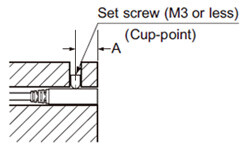
| Model No. | A (mm in) | Tightening torque |
|---|---|---|
| GP-X3SE | 4 to 16 0.157 to 0.630 | 0.10 N·m or less |
| GP-X5SE | 5 to 16 0.197 to 0.630 | 0.44 N·m or less |
| GP-X8S | 0.58 N·m or less |
- The tightening torque should be under the value given below.
- Make sure to use an M3 or smaller set screw having a cup-point.
Mounting with nut
<GP-X10M>
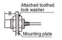
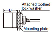
| Model No. | B (mm in) | Tightening torque |
|---|---|---|
| GP-X10M | 7 0.276 or more | 9.8 N·m or less |
| GP-X12ML | 14 0.551 or more | 20 N·m or less |
| GP-X22KL | 20 0.787 or more (Note 1) | 20 N·m or less |
Notes:
1)Without nut. If a nut is installed, the dimension will be 23.5 mm 0.926 in or more.
2)Mount such that the nuts do not protrude from the threaded portion.
Distance from surrounding metal
<Embedding of the sensor head in metal>
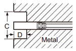
| Sensor head | C (mm in) | D (mm in) |
|---|---|---|
| GP-X3SE | ø10 ø0.394 | 3 0.118 |
| GP-X5SE | ||
| GP-X8S | ø18 ø0.709 | |
| GP-X10M | ø14 ø0.551 | |
| GP-X12ML | ø50 ø1.969 | 14 0.551 |
| GP-X22KL | ø50 ø1.969 | 20 0.787 |
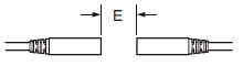
Mutual interference
<Face to face mounting>
<Parallel mounting>
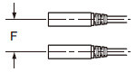
| Sensor head | E (mm in) | F (mm in) |
|---|---|---|
| GP-X3SE | 15 0.591 | 9 0.354 |
| GP-X5SE | 30 1.181 | 11 0.433 |
| GP-X8S | 40 1.575 | 15 0.591 |
| GP-X10M | 40 1.575 | 15 0.591 |
| GP-X12ML | 170 6.693 | 50 1.969 |
| GP-X22KL | 200 7.874 | 200 7.874 |
- As metal around the sensor head may affect the sensing performance, pay attention to the following points.
- Since the analog output may change if the sensor head is completely embedded in metal, keep the minimum distance specified in the table below.
- If several sensor heads are mounted close together, some specifications may not be satisfied. Therefore, proceed with the interference prevention function enabled.
The interference prevention function eliminates interference among sensors by alternating sensor oscillations. Contact our office for details about time charts etc. If not using the interference prevention function, leave a distance more than the values given below.
Sensing range
Correction coefficient
| GP-X3SE GP-X5SE GP-X8S GP-X10M GP-X12ML GP-X22KL | |
|---|---|
| Stainless steel (SUS304), Iron | 1 |
| Aluminum | 0.5 approx. |
- The sensing range is specified for the standard sensing object [stainless steel (SUS304) / iron [Cold rolled carbon steel (SPCC)], 60 × 60 × t 1 mm 2.362 × 2.362 × t 0.039 in]. For sensing metals other than the standard sensing objects, use the correction coefficient stated below as a guideline. Verify with the actual sensor before using.
Others
- After turning on the power, wait 15 min. or more [20 min.for the GP-XC3SE(-P) and GP-XC5SE(-P)] before usingthe product.
The power supply circuit is not stable immediately after the power is turned on, and this may cause measurement values to be distorted. In addition, note that there will also be a muting period of approx. 2 sec.