------------------------------ Tab1 showing ------------------------------
Discontinued Products

------------------------------ Tab2 showing ------------------------------
------------------------------ Tab3 showing ------------------------------
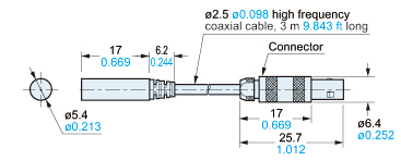
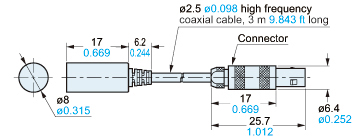
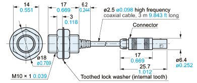
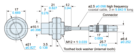
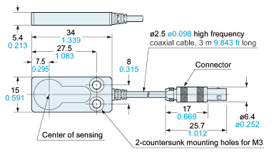
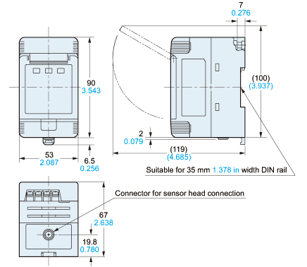
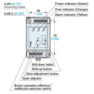
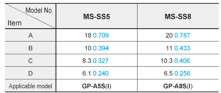
Dimensions
- Unit: mm in
Sensor head
GP-A5S(I)
GP-A8S(I)
GP-A10M(I)
GP-A12ML(I)
GP-A14F(I)
Amplifier
All models
Cover removed condition
MS-SS5 MS-SS8
Mounting bracket for GP-A5S(I) (Optional),
Mounting bracket for GP-A8S(I) (Optional)
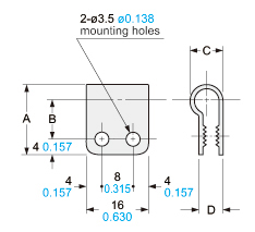
Material:Nylon 66
------------------------------ Tab4 showing ------------------------------
I/O Circuit and Wiring diagrams
I/O circuit diagram
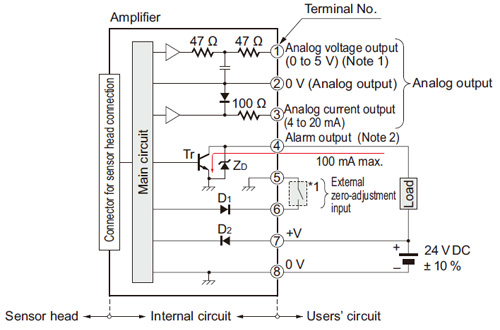
Notes:
1)
In case of using the analog voltage output, connect a device having a high input impedance. Also, take care that the output voltage is reduced due to the resistance of the wiring cable.
2)
The alarm output is not incorporated with a short-circuit protection circuit. Do not connect it directly to a power supply or a capacitive load.
Symbols・・・
D1: Input protection diode
D2: Reverse supply polarity protection diode
ZD: Surge absorption zener diode
Tr : NPN output transistor
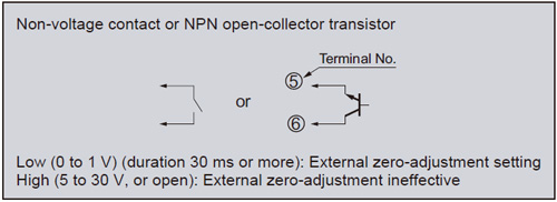
Wiring diagram
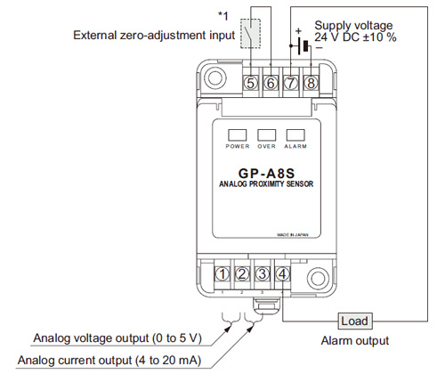
Note:
After the wiring, make sure to fit the terminal covers. The terminal cover having a concave depression at the top should be fitted on the side having terminal Nos. 1 to 4.
*1
------------------------------ Tab5 showing ------------------------------
Sensing characteristics
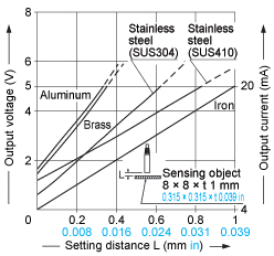
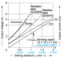
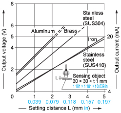
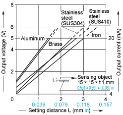
Correlation between material and output voltage / current
The GP-A series is made for all types of standard iron sensing objects. The graph below describes the output discrepancies that occur when detecting different types of metals.
GP-A5S(I)
GP-A8S(I) GP-A10M(I)
GP-A12ML(I)
GP-A14F(I)
------------------------------ Tab6 showing ------------------------------
・Make sure to use in combination the sensor head and amplifier which have the same production serial number (5 digits). Since adjustment is done before shipment, if items with different production serial numbers are combined, the sensing characteristics will deteriorate even if they have the same model number.
・The length of the sensor head cable cannot be changed.
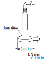
Linearity in case of disc-shaped or cylindrical objects
| Model No. | Iron disc diameter ø (mm in) | Iron cylinder diameter ø (mm in) |
|---|---|---|
| GP-A5S(I) | 12 0.472 | 10 0.394 |
| GP-A8S(I) | 12 0.472 | 10 0.394 |
| GP-A10M(I) | 12 0.472 | 10 0.394 |
| GP-A12ML(I) | 30 1.118 | 50 1.969 |
| GP-A14F(I) | 12 0.472 | 10 0.394 |
- In case the sensing object is disc-shaped or cylindrical, the linearity of the analog output varies with the sensing object size. In such a case, conduct zero adjustment when close mounting and, by adjusting to the maximum sensing distance and to 5 V as the voltage output (current output 20 mA), linearity (±0.5 % F.S.) can be attained on a full-scale if the sensing object’s size is larger than those described in the table below.

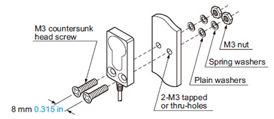
Mounting sensor head
Mounting with set screw
<Non-threaded type sensor head>
| Model No. | A (mm in) | Tightening torque |
|---|---|---|
| GP-A5S(I) | 5 0.197 or more | 0.44 N·m |
| GP-A8S(I) | 0.58 N·m |
Note:
Do not apply excess torque.
Mounting with nut
<Threaded type sensor head>
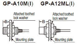
| Model No. | B (mm in) | Tightening torque |
|---|---|---|
| GP-A10M(I) | 7 0.276 or more | 9.8 N·m |
| GP-A12ML(I) | 14 0.551 or more | 20 N·m |
Note: Install in such as way so that the nut does not protrude from the screw.
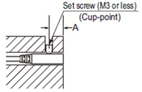
Mounting GP-A14(l)
- The tightening torque should be under the value given below.
- Make sure to use an M3 or smaller set screw having a cup-point.
- The tightening torque should be under the value given below.
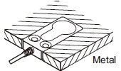
Distance from surrounding metal
<Embedding of the sensor in metal>
- GP-A14F(I) can be used by being completely embedded in metal.
However, the surrounding metal should not protrude beyond the
sensing face.
<Non-threaded type sensor head
threaded type sensor head>
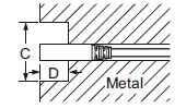
<Front sensing type sensor head>
| Model No. | C (mm in) | D (mm in) |
|---|---|---|
| GP-A5S(I) | ø18 ø0.709 | 4 0.157 |
| GP-A8S(I) | ||
| GP-A10M(I) | 7 0.276 | |
| GP-A12ML(I) | ø50 ø1.969 | 14 0.551 |
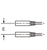
Mutual interference
- When two or more sensor
heads are installed in
parallel or face to face, since
the specifications may not
be met, keep the minimum
separation distance
specified in the table below.
<Non-threaded type sensor head
threaded type sensor head>
<Front sensing type sensor head>
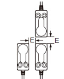
| Model No. | E (mm in) | |
|---|---|---|
| Between “I” type and non-“I” type | Between two “I” types or two non-“I” types | |
| GP-A5S(I) | 11 0.433 | 36 1.417 |
| GP-A8S(I) GP-A10M(I) | 11 0.433 | 38 1.496 |
| GP-A12ML(I) | 14 0.551 | 130 5.118 |
| GP-A14F(I) | 0 0 | 30 1.181 |
Notes:
1) “I” type is different frequency type.
2) If the required resolution is lower than the specification (0.04 % F.S.), it is possible to bring the sensor heads nearer than the separation distances given in the table above. For further details, please contact our office.
- As metal around the sensor may affect the sensing performance, pay attention to the following points.
- Since the analog output may change if the sensor is completely embedded in metal, keep the minimum distance specified in the table below.
Dimensions of suitable crimp terminals
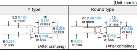
Note:
Please use crimp terminals which have insulation sleeves.
Recommended crimp terminal: Type 1.25 – 3.0
Others
- Do not use during the initial transient time (0.5 sec.) after the power supply is switched on.
- Do not use the sensor at places having intense vibrations, as this can cause malfunction.