------------------------------ Tab1 showing ------------------------------
Discontinued Products

------------------------------ Tab2 showing ------------------------------
Specifications
Sensor heads
| Type | Small object detection | High precision | Long sensing range | |||||
|---|---|---|---|---|---|---|---|---|
| Model No. | GD-3 | GD-10 | GD-20 | |||||
| Applicable controllers | GD-C3 | GD-C1, GD-C2, GD-C3 | GD-C1, GD-C2 | |||||
| Sensing range (between sensor heads) | 10 mm 0.394 in or less | 30 mm 1.181 in or less | 70 mm 2.756 in or less | |||||
| Detectable sheet thickness (Note 2) | Standard sensing object size: 20 x 20 mm 0.787 x 0.787 in | Standard sensing object size: 80 x 80 mm 3.150 x 3.150 in | Standard sensing object size: 200 x 200 mm 7.874 x 7.874 in | |||||
| Setting distance | 5 mm 0.197 in | 10 mm 0.394 in | 20 mm 0.787 in | 30 mm 1.181 in | 35 mm 1.378 in | 70 mm 2.756 in | ||
| Material | Applicable controllers | |||||||
| Iron (SPCC) | GD-C1/C2 | - | - | 0.07 to 1 mm 0.003 to 0.039 in | 0.07 to 0.5 mm 0.003 to 0.020 in | 0.07 to 10 mm 0.003 to 0.394 in | 0.07 to 6 mm 0.003 to 0.236 in | |
| GD-C3 | 0.01 to 0.1 mm 0.0004 to 0.004 in | 0.03 to 0.1 mm 0.001 to 0.004 in | 0.01 to 0.3 mm 0.0004 to 0.012 in | 0.01 to 0.1 mm 0.0004 to 0.004 in | - | - | ||
| Aluminum | GD-C1/C2 | - | - | 0.03 to 6 mm 0.001 to 0.236 in | 0.03 to 2 mm 0.001 to 0.079 in | 0.03 to 10 mm 0.001 to 0.394 in | 0.03 to 6 mm 0.001 to 0.236 in | |
| GD-C3 | 0.015 to 1 mm 0.001 to 0.039 in | 0.015 to 1 mm 0.001 to 0.039 in | 0.015 to 1 mm 0.001 to 0.039 in | 0.015 to 1 mm 0.001 to 0.039 in | - | - | ||
| Copper | GD-C1/C2 | - | - | 0.03 to 6 mm 0.001 to 0.236 in | 0.03 to 2 mm 0.001 to 0.079 in | 0.03 to 10 mm 0.001 to 0.394 in | 0.03 to 6 mm 0.001 to 0.236 in | |
| GD-C3 | 0.018 to 1 mm 0.001 to 0.039 in | 0.018 to 0.3 mm 0.001 to 0.012 in | 0.018 to 1 mm 0.001 to 0.039 in | 0.018 to 1 mm 0.001 to 0.039 in | - | - | ||
| Brass | GD-C1/C2 | - | - | 0.03 to 6 mm 0.001 to 0.236 in | 0.03 to 2 mm 0.001 to 0.079 in | 0.03 to 10 mm 0.001 to 0.394 in | 0.03 to 6 mm 0.001 to 0.236 in | |
| GD-C3 | 0.03 to 1 mm 0.001 to 0.039 in | 0.03 to 0.5 mm 0.001 to 0.020 in | 0.01 to 1 mm 0.0004 to 0.039 in | 0.01 to 1 mm 0.0004 to 0.039 in | - | - | ||
| Stainless steel (SUS304) | GD-C1/C2 | - | - | 0.1 to 6 mm 0.004 to 0.236 in | 0.1 to 2 mm 0.004 to 0.079 in | 0.1 to 10 mm 0.004 to 0.394 in | 0.1 to 6 mm 0.004 to 0.236 in | |
| GD-C3 | 0.3 to 1 mm 0.012 to 0.039 in | 0.3 to 1 mm 0.012 to 0.039 in | 0.05 to 2 mm 0.002 to 0.079 in | 0.05 to 1 mm 0.002 to 0.039 in | - | - | ||
| Protection | IP67 (IEC) | IP67 (IEC), IP67G | ||||||
| Ambient temperature | -10 to +60 ℃ +14 to +140 ℉, Storage: -25 to +70 ℃ -13 to +158 ℉ | |||||||
| Ambient humidity | 45 to 85 % RH, Storage: 35 to 95 % RH | |||||||
| Vibration resistance | 10 to 55 Hz frequency, 1.5 mm 0.059 in double amplitude in X, Y and Z directions for two hours each | |||||||
| Shock resistance | 1,000 m/s2 acceleration (100 G approx.) in X, Y and Z directions three times each | |||||||
| Material | Enclosure: Stainless steel (SUS303), Sensing face: ABS | Enclosure: Polyalylate | Sensing face: Polyacetal, Main body: Stainless steel | |||||
| Cable | Sender: 0.3 mm2 single core shielded cable, 3 m 9.843 ft long Receiver: 0.1 mm2 2-core shielded cable, 3 m 9.843 ft long | Sender: 0.5 mm2 single core shielded cable, 3 m 9.843 ft long Receiver: 0.3 mm2 2-core shielded cable, 3 m 9.843 ft long | ||||||
| Cable extension | Extension up to total 20 m 65.617 ft is possible with an equivalent shielded cable. | |||||||
| Weight | Net weight: 90 g approx. | Net weight: 80 g approx. | Net weight: 440 g approx. | |||||
| Accessory | - | Sensor head mounting bracket: 1 set for sender and receiver | - | |||||
Note 1 : Where measurement conditions have not been specified precisely, the conditions used were an ambient temperature of +20 ℃ +68 ℉.
Note 2 : The above detectable sheet thicknesses are typical data at the given sensing distance. The allowable thickness will differ from the range described in the above table at other setting distances. Further, double feeds of aluminum foils can also be detected at distances shorter than the above.
Please contact our office for details.
Controllers
| Type | Standard | With RS-232C communication function | Small object detection | ||
|---|---|---|---|---|---|
| Model No. | GD-C1 | GD-C2 | GD-C3 | ||
| Supply voltage | 12 to 24 V DC ± 10 % Ripple P-P 10 % or less | ||||
| Current consumption | 12 V DC: 700 mA or less, 24 V DC: 400 mA or less | ||||
| Outputs OUT-1, OUT-2, ALM. Answer-back | NPN open-collector transistor ・Maximum sink current: 100 mA ・Applied voltage: 30 V DC or less (between output and 0 V) ・Residual voltage: 1 V or less (at 100 mA sink current) 0.4 V or less (at 16 mA sink current) | ||||
| Output operation | OUT-1 | OFF above the one-sheet threshold level | |||
| OUT-2 | OFF above the two-sheet threshold level | ||||
| A L M. | OFF when an error occurs | ||||
| Answer-back (ANS. OUT) | Refer to the time chart. (Note 2) | ||||
| Short-circuit protection | Incorporated | ||||
| Response time | Automatically selected either 5 ms or less, or 30 ms or less, depending on the object | 5 ms or less | |||
| Set level storage function | Set values of eight channels stored | ||||
| Set level teaching function | Incorporated | ||||
| External setting function | Incorporated | ||||
| Indicators | Power | Green LED (lights up when the power is ON) | |||
| Self-diagnosis (ALM.) | Red LED (lights up during SET mode and when an error occurs during RUN mode) | ||||
| Sensing mode (SENSE) | 2-color indicator (lights up green during normal sensing mode, but yellow during precise sensing mode) | ||||
| Comparative output-1 (OUT-1) | Green LED (lights up when OUT-1 is OFF, and blinks twice on completion of 0-ADJ. or SET-1 setting in SET mode) | ||||
| Comparative output-2 (OUT-2) | Red LED (lights up when OUT-2 is OFF, and blinks twice on completion of 0-ADJ. or SET-2 setting in SET mode) | ||||
| Sensing level | Yellow LED x 1 and green LED x 6 (indicate the sensing level) | ||||
| Timer function | Approx. 50 ms fixed delay timer (switchable either effective or ineffective) | ||||
| Ambient temperature | -10 to +50 ℃ +14 to +122 ℉ (No dew condensation or icing allowed), Storage: -25 to +70 C° -13 to +158 ℉ | ||||
| Ambient humidity | 45 to 85 % RH, Storage: 35 to 90 % RH | ||||
| Voltage withstandability | 1,000 V AC for one min. between all supply terminals connected together and enclosure | ||||
| Insulation resistance | 50 MΩ, or more, with 250 V DC megger between all supply terminals connected together and enclosure | ||||
| Vibration resistance | 10 to 55 Hz frequency, 0.75 mm 0.030 in double amplitude in X, Y and Z directions for two hours each | ||||
| Shock resistance | 300 m/s2 acceleration (30 G approx.) in X, Y and Z directions three times each | ||||
| Material | Heat-resistant ABS | ||||
| Weight | Net weight: 440 g approx. | ||||
| Accessory | Insulation plate: 2 pcs. | ||||
Note 1 : Where measurement conditions have not been specified precisely, the conditions used were an ambient temperature of +20 ℃ +68 ℉.
Note 2 : Time chart

------------------------------ Tab3 showing ------------------------------
Dimensions
- Unit: mm in
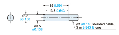
GD-3
Sensor head
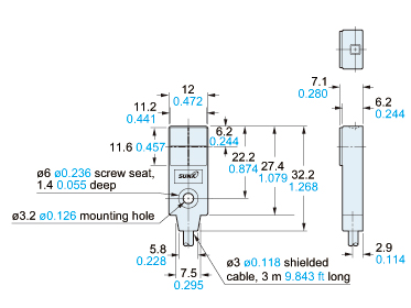
GD-10
Sensor head
GD-20
Sensor head

Sensor head mounting bracket set (Accessory for GD-10)
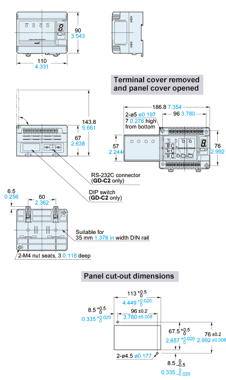
GD-C1 GD-C2 GD-C3
Controller
Sensor head mounting bracket set (Accessory for GD-10)
Mounting hole dimensions
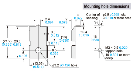
Material:Cold rolled carbon steel (SPCC)(Nickel plated)1 pc. each of M3 (length 12 mm0.472 in) pan head screw, nut, plain washer, spring washer, and anti-slip rubber washer (ø9.5 x t 0.5 mmø0.374 x t 0.020 in) is attached.
------------------------------ Tab4 showing ------------------------------
I/O Circuit and Wiring diagrams
Wiring diagram
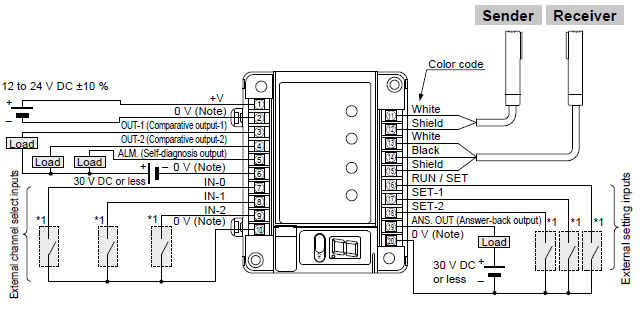
Non-voltage contact or
NPN open-collector transistor
Low : 0 to 1 V
High: 4.5 to 30 V, or open
Note:
Terminal [2, 0 V of power supply, is isolated from 0 V of input / output circuitry for noise immunity. However, if you expect to share the power supply with the output loads, connect terminals [2] and [6] , terminals [2] and [10] , or terminals [2] and [20] to make 0 V common.
I/O circuit diagram
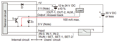
Note:
0 V of power supply is isolated from 0 V of input / output circuitry. To share the power supply with a load, both the 0 V terminals should be short-circuited.
Symbols・・・
D : Reverse supply polarity protection diode
ZD : Surge absorption zener diode
Tr : NPN output transistor
External channel select truth table
Classification by IEC 60825-1
| Channel No. | Input | ||
|---|---|---|---|
| IN-0 | IN-1 | IN-2 | |
| 1 | L | H | H |
| 2 | H | L | H |
| 3 | L | L | H |
| 4 | H | H | L |
| 5 | L | H | L |
| 6 | H | L | L |
| 7 | L | L | L |
| 8 | H | H | H |
L: Low (0 to 1 V), H: High (4.5 to 30 V, or open)
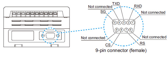
RS-232C wiring diagram (GD-C2 only)
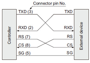
TXD : Transmit data, command
RXD: Receive data, command
RS : Request-to-send
CS : Clear-to-send
SG : Signal ground
Pin arrangement
------------------------------ Tab5 showing ------------------------------
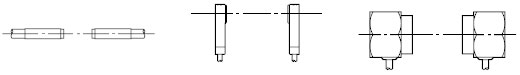
- Make the sender and receiver face each other and align their sensing center line.
- Keep a distance from any magnet or a device generating magnetic field. It may degrade the detectability.
- Surrounding metal influences the detectability. Please contact our office for more details.
- If more than one set of sensor heads are closely mounted, detectability may be affected. Please contact our office for more details.
Mounting sensor heads
<GD-3>
Mounting with set screw
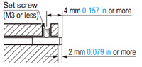
- Use a set screw (M3 or less), and the tightening torque should be 0.12 N·m or less.
<GD-10>
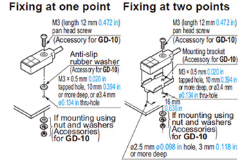
- The tightening torque should be 0.5 N·m or less.
- To mount the sensor head with a nut, the thru-hole should be ø3.4 mm ø0.134 in.
(The mounting board must be 2.3 mm 0.091 in, or less, thick.)
<GD-20>
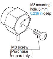
- The tightening torque should be 11.2 N·m or less.
Mounting of controller
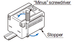
<On DIN rail>
[1] With the stopper pressed in the direction of the arrow (it locks), fit the front portion of the mounting section of the amplifier on the 35 mm 1.378 in width DIN rail.

[2] Press and fit the rear portion of the mounting section on the 35 mm 1.378 in width DIN rail.
* To remove, insert a “minus” screwdriver into the stopper and pull out.
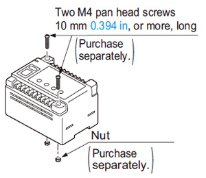
- Use two M4 pan head screws 10 mm 0.394 in, or more, long. The tightening torque should be 1.2 N·m or less.
Sensing mode
- The GD series has two sensing modes, one is the normal sensing mode and the other is the precise sensing mode. They are automatically selected by the characteristics of the object.
Normal sensing mode:
The GD series goes into this mode when the number of objects (e.g., large metal sheets) is distinguished with relative ease.
Precise sensing mode:
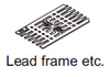
The GD series goes into this mode when the number of objects (e.g., lead frames) is difficult to distinguish. In this mode, the sensitivity difference is so minute between two sensing levels that vibration and temperature changes must be carefully managed.
- The sensing mode indicator lights up green during the normal sensing mode, but lights up yellow during the precise sensing mode.
Sensitivity setting
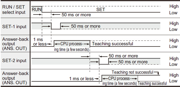
- Teaching by external input
The teaching can also be performed by external input signals.
Time chart
Distance from nearby metals
- As metals near the sensor head may affect the sensing performance, pay attention to the following points.
- The sensor head must be separated from nearby metal by a minimum distance as specified in the table below.
GD-3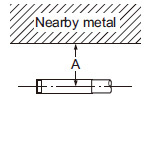
GD-10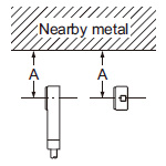
GD-20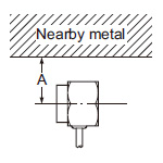
| Setting distance | 5mm 0.197 in | 10mm 0.394 in | 30mm 1.181 in | 70mm 2.756 in |
|---|---|---|---|---|
| GD-3 | 15mm 0.591 in | 20mm 0.787 in | ── | ── |
| GD-10 | 100mm 3.937 in | ── | ||
| GD-20 | 100mm 3.937 in | |||
- The sensing performance may be affected if the sensor is completely embedded in a metal. Keep a minimum clearance between the sensor head and the metal as specified in the table below.
GD-3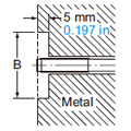
GD-10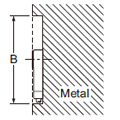
GD-20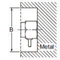
| Setting distance | 5mm 0.197 in | 10mm 0.394 in | 30mm 1.181 in | 70mm 2.756 in |
|---|---|---|---|---|
| GD-3 | ø15mm ø0.591 in | ø20mm ø0.787 in | ── | ── |
| GD-10 | ø100mm ø3.937 in | ── | ||
| GD-20 | ø300mm ø11.811 in | |||
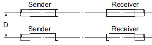
Interference prevention
- When two or more sensor heads are mounted in parallel, keep a minimum separation distance as specified below to avoid interference.
In case the sender and another sensor’s receiver are placed adjacently

| Setting distance(Note) | 5mm 0.197 in | 10mm 0.394 in | 20(35)mm 0.787 (1.378) in | 30(70)mm 1.181 (2.756) in |
|---|---|---|---|---|
| GD-3 | 60mm 2.362 in | 80mm 3.150 in | ── | ── |
| GD-10 | 160mm 6.299 in | 220mm 8.661 in | ||
| GD-20 | 370mm 14.567 in | 630mm 24.803 in | ||
Note: The value in the brackets is for GD-20.
In case the respective senders and receivers are placed adjacently
| Setting distance(Note) | 5mm 0.197 in | 10mm 0.394 in | 20(35)mm 0.787 (1.378) in | 30(70)mm 1.181 (2.756) in |
|---|---|---|---|---|
| GD-3 | 30mm 1.181 in | 50mm 1.969 in | ── | ── |
| GD-10 | 200mm 7.874 in | 250mm 9.843 in | ||
| GD-20 | 450mm 17.717 in | 700mm 27.559 in | ||
Note: The value in the brackets is for GD-20.
RS-232C data transmission (GD-C2 only)
- GD-C2 can feed in the set level data into a PC or PLC memory using RS-232C serial communication and retrieve it whenever required. In this case, the taught data should be stored in the prescribed channel.
Transmission specifications
- Baud rate: Selectable from 300, 600, 1,200, 2,400, 4,800, 9,600, 19,200, 31,250 bits/sec.
- Format: Data bits・・・7 bits or 8 bits
Parity check・・・None or Enable, Even or Odd
Stop bits・・・1 bit or 2 bits
Terminal code・・・CR or ETX
Self-diagnosis (Alarm) function
- The GD series constantly runs self-diagnosis, outputs the result with self-diagnosis output, and lights the selfdiagnosis indicator. In addition, error content is shown on the channel display using error codes.
Others
・Do not operate the sensor for a few seconds immediately after supplying power because of transient conditions including self-diagnosis time.
- Make sure to check the ability of the sensor to detect the number of sheets of your actual objects before use. If real objects differ from teaching samples in size or in characteristics, or the detecting condition deviates, an error may occur. Please note that magnetic metals or metals with low magnetic permeability such as steel especially have a strong tendency.
- In situations when magnets are in close proximity such as during electromagnet conveyance, this causes malfunctions due to electromagnetic disorder.
- When conducting minute detections, favorable sensing conditions are obtained only after having elapsed 60 min. after the initial introduction of the power supply.