------------------------------ Tab1 showing ------------------------------
Discontinued Products

------------------------------ Tab2 showing ------------------------------
System Configuration
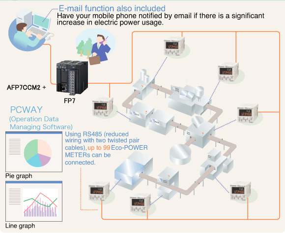
Example 1. Electric power watching using PLC with Eco-POWER METER
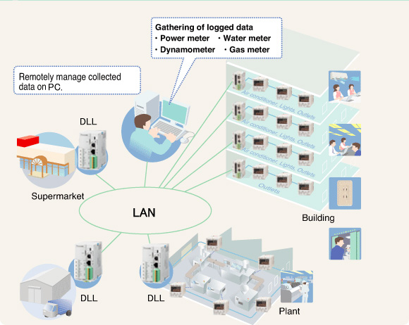
Example 2. Electric power monitoring using DLL and Eco-POWER METER
------------------------------ Tab3 showing ------------------------------
Rating/ Performance
Measurement items
| Item | Unit | Data display range | |
|---|---|---|---|
| Instantaneous electrical power | kW | 0.00 to 9999.99 | |
| Integrated electrical energy | kWh MWh | 0.00 to 9999.99 kWh to | |
| 10.00 MWh to 9999.99 MWh | |||
| When 9-digit display: 0.00 to 9999999.99 kWh | |||
| Current | L1(CT1)phase current | A | 0.0 to 6000.0 |
| L2(CT2)phase current | A | 0.0 to 6000.0 | |
| Voltage | Voltage between 1-2 | V | 0.0 to 9999.9 |
| Voltage between 2-3 | V | 0.0 to 9999.9 | |
| Electricity charge (Note) | Yen | JPY | 0 to 999999 |
| Dollars | $ | 0.0 to 99999.9 | |
| Euros | EUR | 0.0 to 99999.9 | |
| Yuan | CNY | 0 to 999999 | |
| No currency | CHG | 0 to 999999 | |
| Conversion carbon dioxide value | kg-CO2 | 0.0 to 999999 | |
| Hour meter | ON time | h(Hour) | 0.0 to 99999.9 |
| OFF time | h(Hour) | 0.0 to 99999.9 | |
| Pulse input | Count | 0 to 999999 | |
Note : Eco-POWER METER is designed chiefly to manage saving energy. It is neither intended nor can it be legally used for billing.
Main unit
| Rated operating voltage | 100-120/200-240V AC | |
|---|---|---|
| Rated frequency | 50/60 Hz common | |
| Rated power consumption | 8VA (240 V AC at +25 ℃ +77 ℉) | |
| Allowable operating voltage range | 85 to 132/170 to 264V AC (85% to 110% of rated operating voltage) | |
| Allowable momentary power-off time | 10ms | |
| Ambient temperature | -10 to +50 ℃ +14 to +122 ℉ (-25 to +70 ℃ -13 to +158 ℉ at storage) | |
| Ambient humidity | 30 to 85% RH (at +20℃ +68 ℉ non-condensing) | |
| Breakdown voltage (initial) | Between the isolated circuits: 2000 V for 1min | [Use as a power meter] ・ Insulated circuit [between (1) and (2), (2) and (3), (1) and (3)] (1) Power terminal [1 (R), 2 (N and S) and 3 (T)] CT input terminal [CT1 (+), CT2 (+) and CT1, 2 (-)] (2) RS485 terminal (+, -) (3) Pulse output terminal (+, -) ・ Outer edge (case) - all terminals [Use as a pulse counter] ・ Insulated circuit [between (1) and (2), (2) and (3), (1) and (3)] (1) Power terminal [1 (R) and 2 (N)], pulse input terminal [CT1 (+) and 0V] (2) RS485 terminal (+, -) (3) Pulse output terminal (+, -) ・ Outer edge (case) - all terminals |
| Insulation resistance (initial) | Between the isolated circuits: 100 MΩ or more (measured with 500 V DC) | |
| Vibration resistance | 10 to 55 Hz (1cycle / min), single amplitude: 0.75 mm 0.03 in (1 hour on 3 axes) | |
| Shock resistance | Min. 294 m/s2 (5 times on 3 axes) | |
| Display method | 6-digit, 7-segment (set value) with backlight and 4-digit, 16-segment (mode), LCD upper section: green, lower section: amber | |
| Power failure memory method | EEPROM (more than 100,000 overwrite) | |
| Protection | IEC standard IP66 (only front panel with rubber gasket) * Mounted in a row, waterproofing property will be lost. | |
| Weight | 140 g approx. (screw terminal type), 130 g approx. (11-pin type) | |
Input specifications
Power Input
| Phase and wire system | Single-phase two-wire system Single-phase three-wire system Three-phase three-wire system | (common) | |
|---|---|---|---|
| Input voltage | Rating | Single-phase two-wire : 100-120/200-240V AC (common) Single-phase three-wire : 100-120V AC Three-phase three-wire : 100-240V AC | |
| Allowance | 85 to 110% of rated input voltage | ||
| Allowable measurement voltage | Single-phase two-wire : 85-132/170-264V AC (common) Single-phase three-wire : 85-132V AC Three-phase three-wire : 85-264V AC | ||
| VT ratio | 1.00 to 99.99 (Set with setting mode) *Voltage transformer (VT) is required when you measure a load with voltage over 240VAC (Allowable measurement voltage). *Secondary current rating of VT is 110V. | ||
| Input current | Primary side rating | <Using the dedicated CT> ・5A/50A/100A/250A/400A (Select with setting mode) <Using a commercial CT with the secondary side current 5A> ・1 to 4000A (Set with setting mode) *Use a CT with secondary side current of 5A when measure 400A or more. | |
| Special functions | Cut-off current | 1.0 to 50.0%F.S | |
| Hour meter threshold current | 1.0 to 100.0%F.S | ||
| Accuracy (without error in CT and VT) | Basic accuracy | Instantaneous electric power, Integrated electric power, Electricity charge and Conversion value | |
| Within ± (2.0 % F.S. + 1 digit) In case of 5 A CT mode. Within ± (2.5 % F.S. + 1 digit) (at +20 ℃ +68 ℉, rated input, rated frequency, power factor 1) Accuracy coverage: 5 to 100 % of rated current | |||
| Current | |||
| Within ± (1.0 % F.S. + 1 digit) (at +20 ℃ +68 ℉ rated input, rated frequency, power factor 1) Accuracy coverage: 5 to 100 % of rated current | |||
| Voltage | |||
| Within ± (1.0 % F.S. + 1 digit) (at +20 ℃ +68 ℉ rated input, rated frequency, power factor 1) | |||
| Hour Meter | |||
| Within ± (0.01 % +1 digit) (at +20 ℃ +68 ℉) [In case power on start or current energizing: Within ± (0.01 % + 1 sec + 1 digit) (at +20 ℃ +68 ℉)] | |||
| Temperature characteristics | Within ± (1.0 % F.S. + 1 digit) In case of 5 A CT mode. Within ± (1.5 % F.S. + 1 digit) (Range of -10 to +50 ℃ +14 to +122 ℉, rated input, power factor 1) | ||
| Frequency characteristics | Within ± (1.0 % F.S. + 1 digit) In case of 5 A CT mode. Within ± (1.5 % F.S. + 1 digit) (Frequency change ± 5 % based on rated frequency, rated input, power factor 1) | ||
Pulse input
| Input mode | Addition (fixed) | |
|---|---|---|
| Max. counting speed | 2 kHz/30 Hz (selectable by mode) | |
| Pulse input | Min. input signal width: 0.25 ms (when 2 kHz selected)/16.7 ms (when 30 Hz selected) ON : OFF ratio = 1 : 1 | |
| Input signal | Contact/No contact (open collector) · Impedance when shorted: 1kohm · Residual voltage when shorted: Max. 2 V · Impedance when open: 100kohm | |
| Output mode | HOLD (over count) | |
| Number of digits | 6 digits display (0 to 999999)(selectable by mode) | |
| Pre-scale setting | Decimal point | Set to 3rd decimal places (Auto-setting) |
| Range | 0.001 to 100.000 (Selectable with setting mode) | |
| Unit | 「CNT」/「l」/「kl」/「m3」 (Selectable with setting mode) (Count value does not change even if the unit setting is changed during counting.) | |
Pulse output (transistor output)
| Number of output points | 1 point | |
|---|---|---|
| Insulation method | Optical coupler | |
| Output type | Open collector | |
| Output capacity | 100mA 30V DC | |
| Pulse width | Approx. 100ms | |
| ON state voltage drop | 1.5V or less | |
| OFF state leakage current | 100 µA or less | |
| Pulse output unit * | When measuring power | 0.001/0.01/0.1/1/10/100 kWh/Alarm (selectable by mode) |
| When measuring pulse input | HOLD (over count) | |
* Power and pulse input are not possible at the same time.
Communication
| Interface | Conforming to RS485 | |
|---|---|---|
| Protocol | MEWTOCOL/Modbus(RTU)(Depending on part number.) | |
| Isolation status | Isolated with the internal circuit | |
| Number of connected units | 99 (max.) (Note1) (Note2) | |
| Transmission distance | 1200m | |
| Transmission speed | 38400/19200/9600/4800/2400bps (selectable with setting mode) | |
| Transmission Format | Data length | 8bit/7bit (selectable with setting mode) (MEWTOCOL type) 7bit (fixed) (MODBUS type) |
| Parity | Not available/Odd number/Even number (selectable with setting mode) | |
| Stop bit | 1bit(fixed) | |
| Communication method | Half-duplex | |
| Synchronous system | Synchronous communication method | |
| Ending resistance | Approx. 120Ω(built-in)(Note3) | |
Note 1:
For RS-485 converter on the computer side, we recommend SI-35 (from LINE EYE Co.,Ltd.).
Note 2:
When using SI-35, SI-35USB or PLC from our company (which can be connected up to 99 units), up to 99 Eco-POWER METER can be connected.In case using this system with the other devices, up to 31 Eco-POWER METER can be connected.
Note 3:
Change the sliding switch of main unit as a terminal station. (Factory setting; General side)
Recommended cable
Use the transmission cables shown below for Eco-POWER METER RS485 communication system.
| Cable | Conductor | Insulator | Cable diameter | Applicable cable | ||
|---|---|---|---|---|---|---|
| Size | Resistance (at 20℃) | Material | Thickness | |||
| Twisted-pair with shield | 1.25 mm20.0019 in2 (AWG16) or more | Max. 16.8 Ω / km | polyethylene | Max. 0.5 mm 0.020 in | Approx. 8.5 mm 0.335 in | HITACHI KPEV-S1.25 mm20.0019 in2 × 1P Belden Inc.9860 |
| 0.5 mm20.0008 in2 (AWG20) or more | Max. 33.4 Ω / km | polyethylene | Max. 0.5 mm 0.020 in | Approx. 7.8 mm 0.307 in | HITACHI KPEV-S0.5 mm20.0008 in2 × 1P Belden Inc.9207 | |
| VCTF | 0.75 mm20.0012 in2 (AWG18) or more | Max. 25.1 Ω / km | PVC | Max. 0.6 mm 0.024 in | Approx. 6.6 mm 0.260 in | VCTF0.75 mm20.0012 in2 × 2C(JIS) |
| Cable | Twisted-pair with shield | VCTF |
|---|---|---|
| section |
|
|
Note 1)
Use shielded type twist cables.
Note 2)
Use only one type of the transmission cables. Do not mix different types of the cables.
Note 3)
Use twist pair cables under a bad noise environment.
DEDICATED CURRENT TRANSFORMER (CT)
Specifications
| Item | Clamp-on typ | ||||
|---|---|---|---|---|---|
| AKW4801B AKW4801C | AKW4802B AKW4802C | AKW4803B AKW4803C | AKW4804B AKW4804C | AKW4808B AKW4808C | |
| CE marking directive compliance | Low Voltage Directive, RoHS Directive | ||||
| Primary side rated current | 5A/50A | 100A | 250A | 400A | 600A |
| Secondary side rated current | 1.67mA/16.7mA | 33.3mA | 125mA | 200mA | 200mA |
| Winding (Turn) | 3000 | 3000 | 2000 | 2000 | 3000 |
| Ratio error | ±2.0%F.S. | ||||
| Through hole | ø10 ø0.39 | ø16 ø0.63 | ø24 ø0.94 | ø36 ø1.42 | ø36 ø1.42 |
| Breakdown voltage (initial) | 1000V AC/1min (Between through hole and output lead wire) | 2000V AC/1min (Between through hole and output lead wire) | |||
| Insulation resistance (initial) | Min. 100 M Ω (at 500 V DC) (Between through hole and output lead wire) | ||||
| Functional vibration resistance | 10 to 55 Hz (1 cycle / min), single amplitude: 0.15 mm 0.01 in (10 min on 3 axes) | ||||
| Vibration resistance | 10 to 55 Hz (1 cycle / min), single amplitude: 0.375 mm 0.01 in (1 hour on 3 axes) | ||||
| Functional shock resistance | Min. 98m/s2(4 times on 3 axes) | ||||
| Shock resistance | Min. 294m/s2(5 times on 3 axes) | ||||
| Output protection level | ±7.5 V with clamp element | ±3.0V with clamp element | |||
| Permissible clamping frequency | 100 times approx. | ||||
| Ambient temperature range | -10 to +50℃ +14 to +122 ℉ (without frost and non-condensing) | ||||
| Storage temperature | -20 to +60℃ -4 to +140 ℉ (without frost and non-condensing) | ||||
| Ambient humidity | 35 to 85%RH(at +20℃ +68 ℉ non-condensing) | ||||
| Dimensions (mm in) (W x H x D) | 23 x 40 x 26.5 0.08 x 0.13 x 0.09 | 30 x46.5 x 32 0.10 x 0.15 x 0.11 | 45 x65 x 34 0.15 x 0.21 x 0.11 | 57 x81 x 38 0.19 x 0.27 x 0.12 | 62.6 x93.3 x 40 0.21 x 0.31 x 0.13 |
| Weight (Relay cable included) | 60 g approx. | 90 g approx. | 200 g approx. | 295 g approx. | 450 g approx. |
| Item | Through type | |||
|---|---|---|---|---|
| AKW4506B AKW4506C | AKW4507B AKW4507C | AKW4508B AKW4508C | ||
| CE marking directive compliance | Low Voltage Directive, RoHS Directive | |||
| Primary side rated current | 50A/100A | 250A/400A | 600A | |
| Secondary side rated current | 16.7mA/33.3mA | 125mA/200mA | 200mA | |
| Winding (Turn) | 3000 | 2000 | 3000 | |
| Ratio error | ±1.0%F.S. | |||
| Through hole | ø17mm ø0.67 in | ø36mm ø1.42 in | ||
| Breakdown voltage (initial) | 1000V AC/1min (Between through hole and output lead wire)) | 2000V AC/1min (Between through hole and output lead wire) | ||
| Insulation resistance (initial) | Min. 100 MΩ (at 500 V DC megger) (Between through hole and output lead wire) | |||
| Functional vibration resistance | 10 to 55 Hz (1 cycle / min), single amplitude: 0.15 mm 0.01 in (10 min on 3 axes) | |||
| Vibration resistance | 10 to 55 Hz (1 cycle / min), single amplitude: 0.375 mm 0.01 in (1 hour on 3 axes) | |||
| Functional shock resistance | Min. 98 m/s2 (4 times on 3 axes) | |||
| Shock resistance | Min. 294 m/s2 (5 times on 3 axes) | |||
| Output protection level | ±7.5 V with clamp element | ±3.0 V with clamp element | ||
| Permissible clamping frequency | - | |||
| Ambient temperature range | –10 to +50 ℃ +14 to +122 ℉ (without frost and non-condensing) | |||
| Storage temperature | –20 to +60 ℃ –4 to +140 ℉ (without frost and non-condensing) | |||
| Ambient humidity | 35 to 80 % RH (at +20 ℃ +68 ℉non-condensing) | |||
| Dimensions (mm in) (W x H x D) | ø42 x 15 1.65 x 0.05 | ø70 x19 2.76 x 0.06 | ø70 x19 2.76 x 0.06 | |
| Weight (Relay cable included) | 70 g approx. | 200 g approx. | 215 g approx. | |
Notes :
1)
Dedicated CT are dedicated for low voltage under 440 V AC system. They can not be used for high voltage circuit.
2)
In each type of Eco-POWER METER excluding AKW8115, KW9M and KW2M, a combination of commercially secondary side 5 A CTs and dedicated CTs for 5 A is used for measuring high voltage circuits; For details, confirm with each respective user's manual.
3)
Since dedicated CTs cannot be used when measuring with AKW8115, KW9M and KW2M, please be careful and do not purchase a dedicated CT by mistake.
4)
For the AKW8115, KW9M and KW2M, CT with a secondary side current 1 A or 5 A is recommended. Please confirm the specification beforehand.
5)
Dedicated CT are not included with Eco-POWER METERs.
6)
Each dedicated CT includes a 1 m 3.281 ft relay cable, respectively.
------------------------------ Tab4 showing ------------------------------
Dimensions
- Unit: mm in
- 1.DIMENSIONS (KW4M)
- 2.DIMENSIONS (Dedicated current transformers CT)
- 3.Terminal arrangement・Wiring diagrams (KW4M)
KW4M
±1.0 ±0.39General tolerance :
Panel Cut-out dimensions
Panel mounting diagram
How to mount
From the panel front, pass the main unit through the square holes. Insert the mounting frame from the rear and push it in so that the gap between the mounting frame and the panel surface is minimized.
Tighten the screws (2 places) equally tight and check that there is no rattling. If the screws are overly tightened, the frame may come off. In that case, loosen the screws and tighten them again pushing the frame in.
Dedicated current transformers CT
Dedicated current transformer (CT) Clamp-on type 5A/50A (AKW4801B)
Dedicated current transformer (CT) Clamp-on type 100A (AKW4802B)
Dedicated current transformer (CT) Clamp-on type 250A (AKW4803B)
Dedicated current transformer (CT) Clamp-on type 400A (AKW4804B)
Dedicated current transformer (CT) Through type 50A/100A (AKW4506B)
Dedicated current transformer (CT) Through type 250A/400A (AKW4507B)
Terminal arrangement
Terminal layout
| No. | Terminal type | ||
|---|---|---|---|
| Pin type | Screw terminal type | ||
| 1 | 1, R, R | RS-485(-) | M3.5 screw with crossrecessed /slotted head |
| 2 | 2, N, S | CT1(k )/IN | |
| 3 | 3, T, T | CT1(ℓ), CT2(ℓ) | |
| 4 | RS-485(+) | CT2(k) | |
| 5 | RS-485(-) | 0V | |
| 6 | Pulse output(+) | Pulse output(+) | |
| 7 | Pulse output(-) | Pulse output(-) | |
| 8 | CT1(k)/IN | 1, R, R | |
| 9 | CT1(ℓ), CT2(ℓ) | 2, N, S | |
| 10 | CT2(k) | 3, T, T | |
| 11 | 0V | RS-485(+) | |
(Note):
For 11-pin type, use DIN rail terminal block (ATC180041).
Power measurement
Main unit wiring diagrams
Please connect a breaker (3 to 15A) to the voltage input part for safety reasons and to protect the device. Grounding the secondary side of VT (Voltage transformer) and CT (Current transformer) is not necessary with low-voltage circuit.
When measuring load with 100-200V system
Single-phase 2 wire system *One CT is required to measure.
Single-phase 3 wire system / Three-phase 3 wire system
*Two CTs are required to measure.
When measuring a load with exceed input voltage.
Voltage transformer (VT) is needed when you measure a load with over rated input voltage (240V). Use VT, those secondary rating is 110V.
Grounding the secondary side of VT and CT is not necessary with low-voltage circuit.
Single-phase 2 wire system
Single-phase 3 wire system / Three-phase 3 wire system
Pulse measurement
Main unit wiring diagrams
Input connection
Note:
Short-circuit impedance should be less than 1kΩ.(When the impedance is 0Ω, drain current is approx. 5mA.)
The open-circuit impedance should be more than 100kΩ.
Note:
Operating power supply input part (measured voltage input) is not insulated to pulse input parts. So the input equipment must have the power supply transformer in which the secondary side is not grounded with the primary and secondary sides insulated, in order to prevent interference of the power supply circuit when connecting the external input circuit. Be sure not to use an auto-transformer.
- Contact input
Use highly reliable metal plated contacts. Since the contact’s bounce time leads directly to error in the count value, use contacts with as short a bounce time as possible. In general, select 30Hz for max. counting speed. - Non-contact input (Transistor input)
Connect with an open collector. Use the transistor with the following specifications.
VCEO=20V min. IC=20mA min. ICBO=6μA max
Use transistors with a residual voltage of less than 1.5V when the transistor is ON.
For Wiring terminal
- When using a crimp terminal, it should be with insulation sleeve applicable to M3.5 screw as shown below.
- Tightening torque: under 0.8N・m
------------------------------ Tab5 showing ------------------------------
エコパワーメータ使用上のご注意(共通)
※商品別の使用上のご注意は仕様書などで必ずご確認ください。
引火性ガス、腐食性ガスの発生するところや、塵埃の多いところ、油のかかるところ、振動、衝撃の激しいところでのご使用は避けてください。
本体ケースは難燃性樹脂を使用していますが、燃えやすいものの側には設置しないでください。また、燃えやすいものの上に直接置くことは避けてください。
本体カバーはポリカーボネート樹脂製ですから、メチルアルコール、ベンジン、シンナーなどの有機溶剤や、アンモニア、苛性ソーダなど、強アルカリ性物質の付着やそれらの雰囲気でのご使用は避けてください。
当社の商品は当社専用オプション品の使用を前提にしております。他社オプション品との組合せには互換性がありませんのでご注意ください。
インバータの2次側回路では使用しないでください。本体の発熱や故障の原因となります。
計測について
高調波、または波形がひずんでいる場合は、正確に計測できないことがありますのでご採用前に、実機にてご確認ください。
サージについて
- 操作電源重畳サージが次の値を越えると、内部回路が破壊することがあるため、サージ吸収素子をご使用ください。
| サージ電圧 | KW1Mシリーズ | その他 |
|---|---|---|
| 4,000V | 6,000V |
|

- 外部ノイズに対しては、下記の値をノイズ電圧としていますが、これ以上になりますと誤動作、内部回路破壊の原因となりますのでご注意ください。
| 操作電源端子間 | |
|---|---|
| ノイズ電圧 | 1,500V |
ノイズ波形(ノイズシミュレータ)
立上り:1ns パルス幅:1μs,50ns
極 性:± 周 期:10ms
※入力ラインに過大なノイズが印加されると、正確に計測できないおそれがあります。
自己診断機能について
| 表示 | 内容 | 出力状態 | 復帰方法 | 付記後の状態 |
|---|---|---|---|---|
| ERR0 | CPU異常 | OFF | 電源再投入 | CPU異常直前の 電源投入時の表示 |
| ERR1 | メモリ異常 | EEP-ROM寿命の ため本体交換 | - |
| ※ | EEP-ROMの書き換え寿命に達した場合も含む。 |
|---|
停電記憶について
エコパワーメータは、電源OFFした時点(停電保証・記憶)までの積算電力量、アワーメータの値、パルスカウント値、動作状態をEEP-ROMに記憶します。そのため、頻度に電源をON/OFFする環境でのご使用は、できるだけお避けください。EEPROMの寿命が早くなります。
AKW1000の場合
各種設定値を変更する毎に設定値をFROMに記憶し、停電しても停電前のデータを保持しています。頻繁に設定変更するとFROM の寿命が早くなりますので、そのような環境でのご使用はお避けください。
AKW1131Bの場合
エコパワーメータは電源OFFした時点(停電記憶)までの積算電力量、アワーメータの値、パルスカウント値、動作状態をEEPROMに記憶します。また各種設定を変更する毎に設定値をEEPROMに記憶します。そのため頻繁に電源をON/OFFまたは、頻繁に設定変更するとEEPROM の寿命が早くなりますので、そのような環境でのご使用はお避けください。
※特に通信による書込み時はご注意ください。
その他
エコパワーメータは、省エネ目的の自主管理用のため課金目的に使用できません。また、計量法を定める指定機関が行う検定に合格した特定計量器ではありませんので電力量の証明には使用できません。
結線について
結線については各商品ページの寸法図ページに記載しておりますので必ずご確認ください。
なお、共通のご注意点は以下の通りです。
安全、本体の保護やメンテナンス性確保のため、計測電圧入力部、操作電源部にはブレーカ(3~15A)などを設置してください。低圧回路において、VT(計器用変圧器)、CT(電流センサ)の2次側接地は不要です。
電流センサ(CT)の取り付け
- エコパワーメータ本体のCT接続部が、コネクタ式の場合は、そのまま本体に接続してください。
|

- CTは、単相2線式を計測する場合は1つ、単相3線式、三相3線式を計測する場合は2つ、三相4線式を計測する場合は3つ必要です。1台のエコパワーメータに使用する全てのCTは同じ定格容量のものをお使いください。
- あらかじめ負荷電線の太さがCTの貫通穴径より小さいことを確認してください。
- 盤内のメイン渡りバー(ブスバー)など導体が露出している箇所にはCTを接続しないでください。感電のおそれがあります。
- CTの接続の際は、必ず先にCTの2次側をエコパワーメータ本体に接続し、その後CTの1次側を負荷電線に配線してください。順序を間違えますと、感電のおそれやCTの故障の原因となります。
- CTには極性があります。CTに記載してある方向(K→L)に合わせて、電源側(K)から負荷側(L)に向けて取付けてください。方向を間違えると、正確に計測できません。
- CTを閉じる際には、分割面にゴミや異物などがないことを確認してください。また閉じた時には、分割面が密着していることを確かめてください。分割面に隙間があると計測誤差が生じます。(分割型のみ)
- 高調波、または波形が歪んでいる場合は、正確に計測できないことがありますので、ご採用前に実機にてご確認ください。
- 計測電圧入力端子、操作電源端子への配線(強電部)とCT単体、CTケーブルはできるだけ離して配線してください。 (磁界やノイズの影響を受け、計測仕様の精度を満足しないことがあります。)
電流センサ(CT)を延長する場合
- 各種専用電流センサに同梱の中継ケーブルの長さは約1mです。
- CTのケーブルを延長する場合、ノイズを全く受けない環境下ではAWG#22以上のケーブルで約10mまで延長できます。極力太いケーブルを使用ください。
※ケーブルを延長する場合は、ご使用前に実機での確認をお願いします。
2次側電流5A CTを接続する場合
2次側電流5A CTと組み合わせて、計測する場合の接続手順
(1) CT 設定モード(CT-T)にて、5A を選択します。
(2) CT1次側電流設定モード(CT-1)にて、計測するCT(2次側電流 5A) の1次側電流を設定します。
〈例〉 計測するCT が400A/5A の場合、"400" と設定します。
(3)エコパワーメータに接続した5A用専用CT (AKW4801B) を2次側電流5A CTの2次側に接続します。
CTの方向(K→L)は2次側電流5A CTの方向(K→L) と合わせてください。
| ※ |
|---|
|

入力の接続について
有接点入力
接点信頼性のよい金メッキ接点のものをご使用ください。
接点バウンス時間はカウント値の誤差になるため、バウンス時間の短いものをご使用ください。この場合、最高計数速度は30Hzを選択ください。
無接点入力(トランジスタ入力)
オープンコレクタで接続してください。
使用するトランジスタの特性としては、VCEO=20V以上、IC=20mA 以上、ICBO=6μA以下のものをご使用ください。また、トランジスタON時の残留電圧1.5V以下のものをご使用ください。
*短絡時インピーダンスは1kΩ以下としてください。0Ω時、パルス入力端子の流出電流は約7mA 、開放時インピーダンスは100kΩ以上としてください。
入力配線
配線はシールド線、又は単独に金属電線管を使用し、配線長10m以下でご使用ください。長くなると電線の浮遊容量の影響を受け、正常に動作しないおそれがあります。
(注意)
操作電源入力部、計測電圧入力部、パルス入力部は、非絶縁となっていますので、各種信号入力の接続に際し、短絡防止のためにセンサ等入力機器の電源は、図Aのように1次、2次の絶縁された電源トランスで、2次側が接地されていないものをご使用ください。2次側が接地された状態、または単巻トランスを使用された場合は、図Bのように短絡状態となり、商品の内部回路が破壊しますのでご注意ください。
|

出力の接続について
本商品のトランジスタ出力は、フォトカプラにて内部回路と絶縁されていますのでNPN出力、PNP(等価)出力のどちらにもお使いいただけます。
|
圧着端子について
圧着端子については各商品ページの寸法図ページに記載しておりますので必ずご確認ください。
低電圧指令について
EN61010-1/IEC61010 - 1を適用する用途にご使用の場合には、以下の条件の下でご使用ください。
- 1.本体のパルス出力部は、基礎絶縁のみ確保しています。EN61010- 1/IEC61010 - 1で要求される強化(二重)絶縁を確保するためには、負荷側で基礎絶縁以上、通信システム側で強化 (二重) 絶縁を確保してください。
- 2.電圧入力部にはEN60947 - 1またはEN60947 - 3規格に適合したブレーカを容易に手の届く位置に配置して、それが機器の遮断装置であることを表示してください。
- 3.電流センサ(CT)をクランプ(接続)する電線は、基礎絶縁以上のものをご使用ください。
使用環境
- 汚染度 2、過電圧カテゴリーII、
- 屋内使用
- 使用温度範囲/使用湿度範囲:-10~+50℃/30~85%RH(20℃にて結露なきこと)
- 標高2,000m以下
本体は下記のような場所でご使用ください。
- 塵埃が少なく、腐食性ガスのないところ。
- 可燃性ガス、爆発性ガスのないところ。
- 機械的振動や衝撃がないところ。
- 直射日光があたらないところ。
- 大容量の電磁開閉器や大電流の流れている電線から離れているところ。