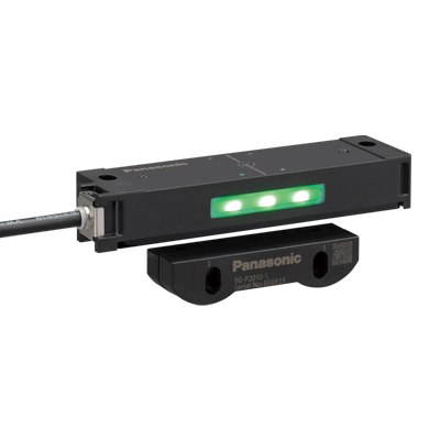
SG-P1010-M-P|Non-Contact Safety Door Switch SG-P
Download

*Photo may vary from actual product.
This product has been confirmed that it does not contain the 6 substances specified in EU RoHS Directive 2011/65/EU and the 4 substances specified in 2015/863/EU.
| Product Number | SG-P1010-M-P |
|---|---|
| Part Number | SG-P1010-M-P |
| Product | Non-Contact Safety Door Switch |
| Details | Compact type |
| Product Name | Non-Contact Safety Door Switch SG-P |
*Specifications and design of the products are subject to change without notice for the product improvement.
Spec Detail
Specifications and design of the products are subject to change without notice for the product improvement.
| Item | Specifications |
|---|---|
| Part Number | SG-P1010-M-P |
| Product Number | SG-P1010-M-P |
| Products Name | Non-Contact Safety Door Switch |
| Product details | Compact type (Low code / Standard) |
| Applicable standards:International standard | ISO 13849-1 : 2015 (Category 4, PLe), IEC 61508-1 to 3 (SIL3), IEC 62061 (SIL3), IEC 60947-5-3, ISO 14119 |
| Applicable standards:Japan | JIS B 9705-1, JIS C 0508-1 to 3 (SIL3), JIS B 9961, JIS C 8201-5-2, JIS B 9710 |
| Applicable standards:Europe | EN ISO 13849-1 : 2015 (Category 4, PLe), EN ISO 14119, EN 60947-5-3, EN 300 330, EN IEC 63000, EN 301 489-1 |
| Applicable standards:North America | CAN/CSA C22.2 No.14, UL508 |
| Applicable regulations and certifications | CE Marking (Machinery Directive, RE Directive, RoHS Directive), UKCA Marking (Supply of Machinery (Safety) Regulations, RE Regulations, RoHS Regulations), TÜV SÜD certification, TÜV SÜD certification (U.S.A., Canada), the U.S.'s radio regulations (FCC) (Note), Canada's radio regulations (ICES-003, RSS-310) (Note), Singapore's radio regulations (IMDA certification) (Note), Thailand's radio regulations (NBTC certification) (Note), Philippines' radio regulations (NTC certification) (Note), Korea's radio regulations (KC certification) (Note), India's radio regulations (WPC certification) (Note), Taiwan's radio regulations (NCC certification) (Note) (Note) : This product uses a weak radio signal for its detection operation. Please confirm compliance with applicable laws in the country of use. |
| Operating distance : Front / Side | Sao (OFF→ON): 5 mm 0.197 in, Sar (ON → OFF): 15 mm 0.591 in |
| Power voltage | 24V DC+10-20% Ripple P-P 10 % or less |
| Current consumption | 30 mA or less |
| Control outputs (OSSD 1, OSSD 2) | PNP open-collector transistor 2 outputs • Maximum source current: 100 mA • Applied voltage: Same as the power supply voltage (PNP output: between control output and +V) • Residual voltage: 2 V or less (source current and sink current: 100 mA) (excluding voltage drop due to cable) • Leakage current: 0.2 mA or less (including power OFF state) • Maximum load capacity: 0.47 μF • Load wiring resistance: 3 Ω or less |
| Control outputs (OSSD 1, OSSD 2):Operation mode | • When the actuator is detected (safe state): ON • When the actuator is not detected (unsafe state or lockout state): OFF • When the switch body (sub) does not detect actuator (series connection): OFF |
| Control output(OSSD):Protection circuit | Incorporated |
| Response time | • For single unit: ON→OFF 100 ms or less, OFF→ON 100 ms or less • For multiple units: Time for single unit + 5 ms x (number of connected units - 1) |
| Check input and output | Dedicated communication line between the switch body (standard) and the switch body (sub) (Note) * It is not for external input and output. (voltage range 0 V to 5 V DC) (Note) : When using the device as a single unit, connect the check input with the check output. |
| Number of units connected in series | 30 units or less (standard 1 unit, sub 29 units) |
| Pollution degree | 3 |
| PFHD | 2.30 × 10⁻¹⁰ |
| DCavg | 99% |
| Environmental resistance:Degree of protection | IP65(IEC) |
| Environmental resistance:Ambient temperature | -10 to +55 ℃ +14 to +131 ℉ (No dew condensation or icing allowed), Storage: -25 to +65 ℃ -13 to +149 ℉ |
| Environmental resistance:Ambient humidity | 30 to 85 % RH, storage: 30 to 95 % RH |
| Environmental resistance:Voltage withstandability | 1,000 V AC for one minute between all supply terminals connected together and enclosure |
| Environmental resistance:Insulation resistance | 20 MΩ or more, with 500 V DC megger between all supply terminals connected together and enclosure |
| Environmental resistance:Vibration resistance | 10 to 55Hz, 1 mm double amplitude, 2 hours each in X, Y, and Z directions |
| Environmental resistance:Shock resistance | 300 m/s2 (approx. 30 G), 3 times each in X, Y, and Z direction |
| Material | Switch body: PBT, PC, SUS (stainless steel), EPDM Actuator: PBT |
| Cable | 6–core cabtyre cable, 5 m 16.404 ft long |
| Connected cable length | • When using only one unit: Maximum cable length of 20 m 65.617 ft between switch body and power supply unit • When connecting multiple units in series: Maximum total cable length of 100 m 328.084 ft, maximum cable length of 20 m 65.617 ft between two adjacent units |
| Weight | Switch body (standard): 180 g approx., Actuator: 10 g approx. |
| Gross weight | 260 g approx. |
| Remark | Where measurement conditions have not been specified precisely, the conditions used were ambient temperature +23 ℃ +73 ℉. ■Transponder specifications Operating frequency: 125 kHz Max. transmitter output: 3.33 μW |
