Discontinued Products
Dimensions
Unit: mm in
GL-18H□
GL-18HL□
Sensor

MS-GL8×10
Sensor mounting bracket for GL-8U type (Optional)

Material: Stainless steel (SUS304)
1 pc. each of M3 (length 12 mm 0.472 in) truss head screw, nut, spring washer and plain washer is attached.
MS-GL18HL
Sensor mounting bracket for GL-18HL type (Accessory)

Material:Aluminum
Two M3 (length 25 mm 0.984 in) pan head screws are attached.
GL-8FU□×10
Sensor

GL-8HU□×10
Sensor

I/O Circuit and Wiring diagrams
NPN output type
GL-18H/18HL type
I/O circuit diagram
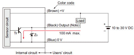
Note: Please carry out the wiring carefully since protection circuit against reverse power supply connection is not incorporated.
Further, the output does not incorporate a short-circuit protection circuit.
Do not connect it directly to a power supply or a capacitive load.
Symbols・・・
ZD: Surge absorption zener diode
Tr : NPN output transistor
Wiring diagram
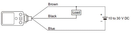
DC 2-wire type
GL-8U type (Discontinued Products)
I/O circuit diagram
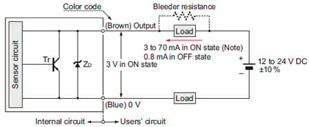
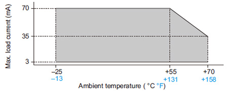
Note: The maximum load current varies depending on the ambient temperature.
Symbols・・・
ZD: Surge absorption zener diode
Tr : NPN output transistor
Wiring diagram
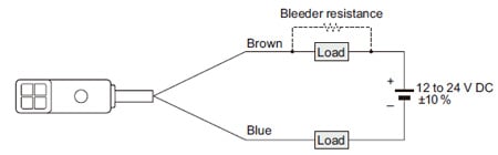
Conditions for the load
- The load should not be actuated by the leakage current (0.8 mA) in the OFF state.
- The load should be actuated by (supply voltage – 3 V) in the ON state.
- The current in the ON state should be between 3 to 70 mA DC
[In case the current is less than 3 mA, connect a bleeder resistance in parallel to the load so that a current of 3 mA, or more, flows.]


As the sensing object size becomes smaller than the standard size (iron sheet 25 × 25 × t 1 mm 0.984 × 0.984 × t 0.039 in), the sensing range shortens as shown in the left figure.


As the sensing object size becomes smaller than the standard size (iron sheet 40 × 40 × t 1 mm 1.575 × 1.575 × t 0.039 in), the sensing range shortens as shown in the left figure.


As the sensing object size becomes smaller than the standard size (iron sheet 15 × 15 × t 1 mm 0.591 × 0.591 × t 0.039 in), the sensing range shortens as shown in the left figure.
Mounting
GL-8U type
- Make sure to mount with an M3 (length 12 mm 0.472 in or more) truss head screw with a tightening torque of 0.5 N·m or less.
(Do not use a flat head screw or a pan head screw.)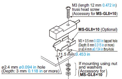
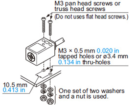
GL-18H/18HL type
- The tightening torque should be 0.5 N·m or less.
- To mount the sensor with a nut, the thru-hole diameter should be ø3.4 mm ø0.134 in.
- Screws, nuts or washers are not supplied. Please arrange them separately.
Influence of surrounding metal
- When there is a metal near the sensor, keep the minimum separation distance specified below.
GL-18H/18HL type
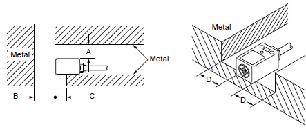
GL-18H□ GL-18HL□ A 5 mm 0.197 in 25 mm 0.984 in B 20 mm 0.787 in 60 mm 2.362 in C 0 mm 0 in 20 mm 0.787 in (Note) D 5 mm 0.197 in 30 mm 1.181 in Note: When mounting the GL-18HL□ to an insulator or using the attached sensor mounting bracket, “C” becomes 0 mm 0 in.
Mutual interference prevention
- When two or more sensors are installed in parallel or face to face, keep the minimum separation distance specified below to avoid mutual interference.
GL-18H/18HL type
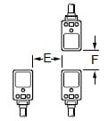
E F GL-18H type Between “I” type and
non “I” type.0 mm (Note 2)
0 in20 mm
0.787 inBetween two “I” types or
two non “I” types.40 mm
1.575 in70 mm
2.756 inGL-18HL type Between “I” type and
non “I” type.20 mm
0.787 in40 mm
1.575 inBetween two “I” types or
two non “I” types.130 mm
5.118 in200 mm
7.874 inNotes:
1) “I” in the model No. specifies the different frequency type.
2) Close mounting is possible for up to two sensors. When mounting three sensors or more at an equal spacing, align the model with “I” and the model without “I” alternately.
The minimum value of dimension “E” should be as given below. GL-18H type: 11 mm 0.433 inSensing range
- The sensing range is specified for the standard sensing object.
With a non-ferrous metal, the sensing range is obtained by multiplying with the correction coefficient specified below.
Further, the sensing range also changes if the sensing object is smaller than the standard sensing object or if the sensing object is plated.
Correction coefficient
GL-8U type GL-18H type GL-18HL type Iron 1 1 1 Stainless steel
(SUS304)0.80 approx. 0.68 approx. 0.65 approx. Brass 0.54 approx. 0.45 approx. 0.42 approx. Aluminum 0.52 approx. 0.43 approx. 0.41 approx. Wiring
- Please carry out the wiring carefully since protection circuit against reverse power supply connection is not incorporated. (Excluding GL-8U type)
- The output does not incorporate a short-circuit protection circuit. Do not connect it directly to a power supply or a capacitive load. (Excluding GL-8U type)
- Make sure that the power supply is off while wiring.
- Verify that the supply voltage variation is within the rating.
- If power is supplied from a commercial switching regulator, ensure that the frame ground (F.G.) terminal of the power supply is connected to an actual ground.
- In case noise generating equipment (switching regulator, inverter motor, etc.) is used in the vicinity of this sensor, connect the frame ground (F.G.) terminal of the equipment to an actual ground.
- Do not run the wires together with high-voltage lines or power lines or put them in the same raceway. This can cause malfunction due to induction.
Others
- Do not use during the initial transient time (50ms) after the power supply is switched on.
- Take care that the sensor does not come in direct contact with oil, grease, or organic solvents, such as, thinner, etc.
- Make sure that the sensing end is not covered with metal dust, scrap or spatter. It will result in malfunction.