Discontinued Products
[Note]
The following applicable products and options are available continuously.
| Designation | Model No. | Description | ||
|---|---|---|---|---|
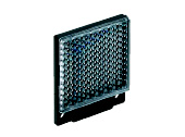
| Reflector (For retroreflective type sensor only) | RF-230 | Accessories | ||
| RF-210 | Sensing range | 0.2 to 1.5 m 0.656 to 4.921 ft [RX-RVM5] 0.4 to 1 m 1.312 to 3.281 ft [RX-PRVM3] | ||
| Min. sensing object | ø30mm ø1.181 in | |||
| RF-220 | Sensing range | 0.1 to 3.8 m 0.328 to 12.467 ft [RX-RVM5] 0.1 to 2 m 0.328 to 6.562 ft [RX-PRVM3] 0.1 to 1.3 m 0.328 to 4.265 ft [RX2-PRVM2] | ||
| Min. sensing object | ø35mm ø1.378 in | |||
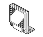
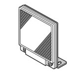
| Reflector mounting bracket | MS-RF21-1 | Protective mounting bracket for RF-210 It protects the reflector from damage and maintains alignment. | ||
| MS-RF22 | For RF-220 | |||
| MS-RF23 | For RF-230 | |||
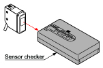
| Sensor checker | CHX-SC2 (Note 1) | It is useful for beam alignment of thru-beam type sensors. The optimum receiver position is given by indicators, as well as an audio signal. | ||
Note 1 :
Refer to the sensor checker CHX-SC2 for details.
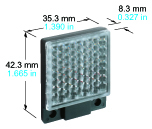
Reflector
RF-230
RF-210
RF-220
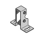
Reflector mounting bracket
MS-RF21-1
Two M3 (length 12 mm0.472 in) screws with washers are attached.
MS-RF22
Two M3 (length 8 mm0.315 in) screws with washers are attached
MS-RF23
Two M4 (length 10 mm0.394 in) screws with washers are attached.
Sensor checker
CHX-SC2
Specifications
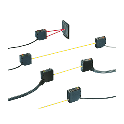
Standard type
| Type | Thru-beam | ||
|---|---|---|---|
| Infrared | |||
| Long sensing range | |||
| Model No. | RX-M10 | RX-M50 | |
| CE marking directive compliance | EMC Directive, RoHS Directive | ||
| Sensing range | 10 m 32.808 ft | 50 m 164.042 ft | |
| Sensing object | φ10 mm 0.394 in or more opaque object (Note 4) | ||
| Hysteresis | - | ||
| Repeatability (perpendicular to sensing axis) | 0.5 mm 0.020 in or less | ||
| Supply voltage | 12 to 24 V DC ±10 % Ripple P-P 10 % or less | ||
| Current consumption | Emitter: 20 mA or less (RX-M50: 25 mA or less), Receiver: 25 mA or less | ||
| Sensing output | NPN open-collector transistor • Maximum sink current: 100 mA • Applied voltage: 30 V DC or less (between sensing output and 0 V) • Residual voltage: 2 V or less (at 100 mA sink current), 1 V or less (at 16 mA sink current) | ||
| Utilization category | DC-12 or DC-13 | ||
| Output operation | Switchable either Light-ON or Dark-ON | ||
| Short-circuit protection | Incorporated | ||
| Self-diagnosis output | NPN open-collector transistor • Maximum sink current: 50 mA • Applied voltage: 30 V DC or less (between self-diagnosis output and 0 V) • Residual voltage: 1.5 V or less (at 50 mA sink current), 1 V or less (at 16 mA sink current) | ||
| Output operation | ON under unstable sensing condition | ||
| Short-circuit protection | - | ||
| Response time | 1 ms or less | ||
| Test input (emission halt) function | Incorporated | ||
| Operation indicator | Red LED (lights up when the sensing output is ON) | ||
| Stability indicator | Green LED (lights up under stable light received condition or stable dark condition) | ||
| Emitting indicator | Red LED (lights up during beam emission) | ||
| Sensitivity adjuster | Continuously variable adjuster | ||
| Automatic interference prevention function | - | ||
| Pollution degree | 3 (Industrial environmrnt) | ||
| Protection | IP67 (IEC) | ||
| Ambient temperature | –25 to +60 ℃ –13 to +140 ℉ (No dew condensation or icing allowed), Storage: –30 to +70 ℃ –22 to +158 ℉ | ||
| Ambient humidity | 35 to 85 % RH, Storage: 35 to 85 % RH | ||
| Ambient illuminance | Incandescent light: 3,500 Lx or less at the light-receiving face | ||
| Voltage withstandability | 1,000 V AC for one min. between all supply terminals connected together and enclosure | ||
| Insulation resistance | 20 MΩ, or more, with 250 V DC megger between all supply terminals connected together and enclosure | ||
| Vibration resistance | 10 to 500 Hz frequency, 1.5 mm 0.059 in double amplitude (10 G max.) in X, Y and Z directions for two hours each | ||
| Shock resistance | 500 m/s2 acceleration (50 G approx.) in X, Y and Z directions three times each | ||
| Emitting element (modulated) | Infrared LED | ||
| Peak emission wavelength | 880 nm 0.035 mil | ||
| Material | Enclosure: Die-cast zinc alloy, Indicator cover: Polyethersulphone, Lens: Polycarbonate | ||
| Cable | Emitter: 0.15 mm2 3-core oil, heat and cold resistant cabtyre cable, 2 m 6.562 ft long Receiver: 0.15 mm2 4-core oil, heat and cold resistant cabtyre cable, 2 m 6.562 ft long | ||
| Cable extension | Extension up to total 100 m 328.084 ft is possible with 0.3 mm2, or more, cable (thru-beam type: both emitter and receiver). | ||
| Net weight | Emitter: 70 g approx. (RX-M50: 75 g approx.) Receiver: 70 g approx. (RX-M50: 75 g approx.) | ||
| Accessories | MS-RX-1 (Sensor mounting bracket) : 1 set for emitter and receiver Adjusting screwdriver : 1 pc. | ||
| Type | Retroreflective | Diffuse reflective | |
|---|---|---|---|
| Infrared (Long sensing range) | Infrared | ||
| Model No. | RX-RVM5 | RX-D700 | |
| CE marking directive compliance | EMC Directive, RoHS Directive | ||
| Sensing range | 0.1 to 5 m 0.328 to 16.404 ft (Note 2) | 700 mm 27.559 in (Note 3) | |
| Sensing object | φ50 mm φ1.969 in or more opaque, or translucent object (Note 2, 5) | Opaque, translucent or transparent object (Note 5) | |
| Hysteresis | - | 15 % or less of operation distance (Note 3) | |
| Repeatability (perpendicular to sensing axis) | 1 mm 0.039 in or less | 0.5 mm 0.020 in or less | |
| Supply voltage | 12 to 24 V DC ±10 % Ripple P-P 10 % or less | ||
| Current consumption | 40 mA or less | ||
| Sensing output | NPN open-collector transistor • Maximum sink current: 100 mA • Applied voltage: 30 V DC or less (between sensing output and 0 V) • Residual voltage: 2 V or less (at 100 mA sink current), 1 V or less (at 16 mA sink current) | ||
| Utilization category | DC-12 or DC-13 | ||
| Output operation | Switchable either Light-ON or Dark-ON | ||
| Short-circuit protection | Incorporated | ||
| Self-diagnosis output | NPN open-collector transistor • Maximum sink current: 50 mA • Applied voltage: 30 V DC or less (between self-diagnosis output and 0 V) • Residual voltage: 1.5 V or less (at 50 mA sink current), 1 V or less (at 16 mA sink current) | ||
| Output operation | ON under unstable sensing condition | ||
| Short-circuit protection | - | ||
| Response time | 1 ms or less | ||
| Test input (emission halt) function | Incorporated | ||
| Operation indicator | Red LED (lights up when the sensing output is ON) | ||
| Stability indicator | Green LED (lights up under stable light received condition or stable dark condition) | ||
| Emitting indicator | - | ||
| Sensitivity adjuster | Continuously variable adjuster | ||
| Automatic interference prevention function | Incorporated (Two units of sensors can be mounted close together.) | ||
| Pollution degree | 3 (Industrial environmrnt) | ||
| Protection | IP67 (IEC) | ||
| Ambient temperature | –25 to +60 ℃ –13 to +140 ℉ (No dew condensation or icing allowed), Storage: –30 to +70 ℃ –22 to +158 ℉ | ||
| Ambient humidity | 35 to 85 % RH, Storage: 35 to 85 % RH | ||
| Ambient illuminance | Incandescent light: 3,500 Lx or less at the light-receiving face | ||
| Voltage withstandability | 1,000 V AC for one min. between all supply terminals connected together and enclosure | ||
| Insulation resistance | 20 MΩ, or more, with 250 V DC megger between all supply terminals connected together and enclosure | ||
| Vibration resistance | 10 to 500 Hz frequency, 1.5 mm 0.059 in double amplitude (10 G max.) in X, Y and Z directions for two hours each | ||
| Shock resistance | 500 m/s2 acceleration (50 G approx.) in X, Y and Z directions three times each | ||
| Emitting element (modulated) | Infrared LED | ||
| Peak emission wavelength | 880 nm 0.035 mil | ||
| Material | Enclosure: Die-cast zinc alloy, Indicator cover: Polyethersulphone, Lens: Polycarbonate (Retroreflective type: Acrylic) | ||
| Cable | 0.15 mm2 5-core oil, heat and cold resistant cabtyre cable, 2 m 6.562 ft long | ||
| Cable extension | Extension up to total 100 m 328.084 ft is possible with 0.3 mm2, or more, cable | ||
| Net weight | 75 g approx. | ||
| Accessories | MS-RX-1 (Sensor mounting bracket): 1 set RF-230 (Reflector): 1 pc. Adjusting screwdriver: 1 pc. | MS-RX-1 (Sensor mounting bracket): 1 set Adjusting screwdriver: 1 pc. | |
Notes:
1)Where measurement conditions have not been specified precisely, the conditions used were an ambient temperature of +23 ℃ +73.4 ℉.
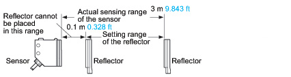
2)The sensing range and the sensing object for the retroreflective type sensor are specified for the RF-230 reflector. Further, the sensing range of RX-PRVM3 and RX-RVM5 is the possible setting range for the reflector. The sensor can detect an object less than 0.1 m 0.328 ft away.
3)The sensing range and the hysteresis of the diffuse reflective type sensor are specified for white non-glossy paper (200 x 200 mm 7.874 x 7.874 in) as the object.
4)If slit masks (optional) are fitted on RX-M10, an object of 0.5 x 5 mm 0.020 x 0.197 in can be detected.
5)Make sure to confirm detection with an actual sensor before use.
| Type | Thru-beam | ||
|---|---|---|---|
| Red | Green | ||
| Model No. | RX-M2R | RX-500G | |
| CE marking directive compliance | EMC Directive, RoHS Directive | ||
| Sensing range | 2 m 6.562 ft | 500 mm 19.685 in | |
| Sensing object | φ10 mm 0.394 in or more opaque object (Note 4) | ||
| Hysteresis | - | ||
| Repeatability (perpendicular to sensing axis) | 0.5 mm 0.020 in or less | ||
| Supply voltage | 12 to 24 V DC ±10 % Ripple P-P 10 % or less | ||
| Current consumption | Emitter: 20 mA or less (RX-M50: 25 mA or less), Receiver: 25 mA or less | ||
| Sensing output | NPN open-collector transistor • Maximum sink current: 100 mA • Applied voltage: 30 V DC or less (between sensing output and 0 V) • Residual voltage: 2 V or less (at 100 mA sink current), 1 V or less (at 16 mA sink current) | ||
| Utilization category | DC-12 or DC-13 | ||
| Output operation | Switchable either Light-ON or Dark-ON | ||
| Short-circuit protection | Incorporated | ||
| Self-diagnosis output | NPN open-collector transistor • Maximum sink current: 50 mA • Applied voltage: 30 V DC or less (between self-diagnosis output and 0 V) • Residual voltage: 1.5 V or less (at 50 mA sink current), 1 V or less (at 16 mA sink current) | ||
| Output operation | ON under unstable sensing condition | ||
| Short-circuit protection | - | ||
| Response time | 1 ms or less | ||
| Test input (emission halt) function | Incorporated | ||
| Operation indicator | Red LED (lights up when the sensing output is ON) | ||
| Stability indicator | Green LED (lights up under stable light received condition or stable dark condition) | ||
| Emitting indicator | Red LED (lights up during beam emission) | ||
| Sensitivity adjuster | Continuously variable adjuster | ||
| Automatic interference prevention function | - | ||
| Pollution degree | 3 (Industrial environmrnt) | ||
| Protection | IP67 (IEC) | ||
| Ambient temperature | –25 to +60 ℃ –13 to +140 ℉ (No dew condensation or icing allowed), Storage: –30 to +70 ℃ –22 to +158 ℉ | ||
| Ambient humidity | 35 to 85 % RH, Storage: 35 to 85 % RH | ||
| Ambient illuminance | Incandescent light: 3,500 Lx or less at the light-receiving face | ||
| Voltage withstandability | 1,000 V AC for one min. between all supply terminals connected together and enclosure | ||
| Insulation resistance | 20 MΩ, or more, with 250 V DC megger between all supply terminals connected together and enclosure | ||
| Vibration resistance | 10 to 500 Hz frequency, 1.5 mm 0.059 in double amplitude (10 G max.) in X, Y and Z directions for two hours each | ||
| Shock resistance | 500 m/s2 acceleration (50 G approx.) in X, Y and Z directions three times each | ||
| Emitting element (modulated) | Red LED | Green LED | |
| Peak emission wavelength | 660 nm 0.026 mil | 570 nm 0.022 mil | |
| Material | Enclosure: Die-cast zinc alloy, Indicator cover: Polyethersulphone, Lens: Polycarbonate | ||
| Cable | Emitter: 0.15 mm2 3-core oil, heat and cold resistant cabtyre cable, 2 m 6.562 ft long Receiver: 0.15 mm2 4-core oil, heat and cold resistant cabtyre cable, 2 m 6.562 ft long | ||
| Cable extension | Extension up to total 100 m 328.084 ft is possible with 0.3 mm2, or more, cable (thru-beam type: both emitter and receiver). | ||
| Net weight | Emitter: 70 g approx. (RX-M50: 75 g approx.) Receiver: 70 g approx. (RX-M50: 75 g approx.) | ||
| Accessories | MS-RX-1 (Sensor mounting bracket) : 1 set for emitter and receiver Adjusting screwdriver : 1 pc. | ||
| Type | Retroreflective | Diffuse reflective | |
|---|---|---|---|
| Red (with polarizing filters) | GreReden | ||
| Model No. | RX-PRVM3 | RX-D200R | |
| CE marking directive compliance | EMC Directive, RoHS Directive | ||
| Sensing range | 0.1 to 3 m 0.328 to 9.843 ft (Note 2) | 200 mm 7.874 in (Note 3) | |
| Sensing object | φ50 mm φ1.969 in or more opaque, translucent or specular object (Note 2, 4) | Opaque, translucent or transparent object (Note 4) | |
| Hysteresis | - | 15 % or less of operation distance (Note 3) | |
| Repeatability (perpendicular to sensing axis) | 1 mm 0.039 in or less | 0.5 mm 0.020 in or less | |
| Supply voltage | 12 to 24 V DC ±10 % Ripple P-P 10 % or less | ||
| Current consumption | 40 mA or less | ||
| Sensing output | NPN open-collector transistor • Maximum sink current: 100 mA • Applied voltage: 30 V DC or less (between sensing output and 0 V) • Residual voltage: 2 V or less (at 100 mA sink current), 1 V or less (at 16 mA sink current) | ||
| Utilization category | DC-12 or DC-13 | ||
| Output operation | Switchable either Light-ON or Dark-ON | ||
| Short-circuit protection | Incorporated | ||
| Self-diagnosis output | NPN open-collector transistor • Maximum sink current: 50 mA • Applied voltage: 30 V DC or less (between self-diagnosis output and 0 V) • Residual voltage: 1.5 V or less (at 50 mA sink current), 1 V or less (at 16 mA sink current) | ||
| Output operation | ON under unstable sensing condition | ||
| Short-circuit protection | - | ||
| Response time | 1 ms or less | ||
| Test input (emission halt) function | Incorporated | ||
| Operation indicator | Red LED (lights up when the sensing output is ON) | ||
| Stability indicator | Green LED (lights up under stable light received condition or stable dark condition) | ||
| Emitting indicator | - | ||
| Sensitivity adjuster | Continuously variable adjuster | ||
| Automatic interference prevention function | Incorporated (Two units of sensors can be mounted close together.) | ||
| Pollution degree | 3 (Industrial environmrnt) | ||
| Protection | IP67 (IEC) | ||
| Ambient temperature | –25 to +60 ℃ –13 to +140 ℉ (No dew condensation or icing allowed), Storage: –30 to +70 ℃ –22 to +158 ℉ | ||
| Ambient humidity | 35 to 85 % RH, Storage: 35 to 85 % RH | ||
| Ambient illuminance | Incandescent light: 3,500 Lx or less at the light-receiving face | ||
| Voltage withstandability | 1,000 V AC for one min. between all supply terminals connected together and enclosure | ||
| Insulation resistance | 20 MΩ, or more, with 250 V DC megger between all supply terminals connected together and enclosure | ||
| Vibration resistance | 10 to 500 Hz frequency, 1.5 mm 0.059 in double amplitude (10 G max.) in X, Y and Z directions for two hours each | ||
| Shock resistance | 500 m/s2 acceleration (50 G approx.) in X, Y and Z directions three times each | ||
| Emitting element (modulated) | Red LED | Red LED | |
| Peak emission wavelength | 680 nm 0.027 mil | 680 nm 0.027 mil | |
| Material | Enclosure: Die-cast zinc alloy, Indicator cover: Polyethersulphone, Lens: Polycarbonate (Retroreflective type: Acrylic) | ||
| Cable | 0.15 mm2 5-core oil, heat and cold resistant cabtyre cable, 2 m 6.562 ft long | ||
| Cable extension | Extension up to total 100 m 328.084 ft is possible with 0.3 mm2, or more, cable | ||
| Net weight | 75 g approx. | ||
| Accessories | MS-RX-1 (Sensor mounting bracket): 1 set RF-230 (Reflector): 1 pc. Adjusting screwdriver: 1 pc. | MS-RX-1 (Sensor mounting bracket): 1 set Adjusting screwdriver: 1 pc. | |
Notes:
1)Where measurement conditions have not been specified precisely, the conditions used were an ambient temperature of +23 ℃ +73.4 ℉.
2)The sensing range and the sensing object for the retroreflective type sensor are specified for the RF-230 reflector. Further, the sensing range of RX-PRVM3 and RX-RVM5 is the possible setting range for the reflector. The sensor can detect an object less than 0.1 m 0.328 ft away.

3)The sensing range and the hysteresis of the diffuse reflective type sensor are specified for white non-glossy paper (200 x 200 mm 7.874 x 7.874 in) as the object.
4)Make sure to confirm detection with an actual sensor before use.
DC 2-wire type
| Type | Thru-beam | Retroreflective (with polarizing filters) | Diffuse reflective | |
|---|---|---|---|---|
| Model No. | RX2-M5 | RX2-PRVM2 | RX2-D300 | |
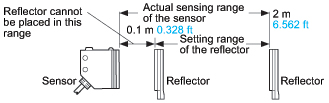
| Sensing range | 5 m 16.404 ft | 0.1 to 2 m 0.328 to 6.562 ft (Note 2) | 300 mm 11.811 in (Note 3) | |
| Sensing object | φ10 mm φ0.394 in or more opaque object (Note 4) | φ50 mm φ1.969 in or more opaque, translucent or specular object (Note 2, 5) | Opaque, translucent or transparent object (Note 5) | |
| Hysteresis | - | - | 15 % or less of operation distance (Note 3) | |
| Repeatability (perpendicular to sensing axis) | 0.5 mm 0.020 in or less | 1 mm 0.039 in or less | 0.5 mm 0.020 in or less | |
| Supply voltage | 12 to 24 V DC ±10 % Ripple P-P 10 % or less | |||
| Current consumption | Emitter: 8 mA or less, Receiver: 0.8 mA or less (Note 6) | 1 mA or less (Note 6) | ||
| Sensing output | Non contact DC 2-wire type • Load current: 5 to 100 mA • Residual voltage: 4 V or less (Note 7) | |||
| Output operation | Switchable either Light-ON or Dark-ON | |||
| Short-circuit protection | Incorporated | |||
| Response time | 3 ms or less | |||
| Operation indicator | Red LED (lights up when the output is ON) | |||
| Stability indicator | Green LED (Light-ON mode: lights up under stable light received condition Dark-ON mode: lights up under stable dark condition) | |||
| Emitting indicator | Red LED (lights up during beam emission) | - | ||
| Sensitivity adjuster | Continuously variable adjuster | |||
| Protection | IP67 (IEC) | |||
| Ambient temperature | –20 to +60 ℃ –4 to +140 ℉ (No dew condensation or icing allowed), Storage: –30 to +70 ℃ –22 to +158 ℉ | |||
| Ambient humidity | 35 to 85 % RH, Storage: 35 to 85 % RH | |||
| Ambient illuminance | Incandescent light: 3,500 Lx or less at the light-receiving face | |||
| Voltage withstandability | 1,000 V AC for one min. between all supply terminals connected together and enclosure | |||
| Insulation resistance | 20 MΩ, or more, with 250 V DC megger between all supply terminals connected together and enclosure | |||
| Vibration resistance | 10 to 500 Hz frequency, 1.5 mm 0.059 in double amplitude (10 G max.) in X, Y and Z directions for two hours each | |||
| Shock resistance | 500 m/s2 acceleration (50 G approx.) in X, Y and Z directions three times each | |||
| Emitting element | Infrared LED (modulated) | Red LED (modulated) | Infrared LED (modulated) | |
| Peak emission wavelength | 880 nm 0.035 mil | 680 nm 0.027 mil | 890 nm 0.035 mil | |
| Material | Enclosure: Die-cast zinc alloy, Indicator cover: Polyethersulphone, Lens: Polycarbonate (RX2-PRVM2: Acrylic) | |||
| Cable | 0.15 mm2 2-core oil, heat and cold resistant cabtyre cable, 2 m 6.562 ft long | |||
| Cable extension | - (Note 7) | |||
| Net weight | Emitter: 70 g approx., Receiver: 70 g approx. | 75 g approx. | 70 g approx. | |
| Accessories | MS-RX-1 (Sensor mounting bracket): 1 set for emitter and receiver Adjusting screwdriver: 1 pc. | MS-RX-1 (Sensor mounting bracket): 1 set RF-230 (Reflector): 1 pc. Adjusting screwdriver: 1 pc. | MS-RX-1 (Sensor mounting bracket): 1 set Adjusting screwdriver: 1 pc. | |
Notes:
1)Where measurement conditions have not been specified precisely, the conditions used were an ambient temperature of +23 ℃ +73.4 ℉.
2)The sensing range and the sensing object for RX2-PRVM2 are specified for the RF-230 reflector. Further, the sensing range is the possible setting range for the reflector. The sensor can detect an object less than 0.1 m 0.328 ft away.
3)The sensing range and the hysteresis of RX2-D300 are specified for white non-glossy paper (200 x 200 mm 7.874 x 7.874 in) as the object.
4)If slit masks (optional) are fitted, an object of 0.5 x 5 mm 0.020 x 0.197 in can be detected.
5)Make sure to confirm detection with an actual sensor before use.
6)It is the leakage current when the output is in the OFF state.
7)When extending the cable, the residual voltage will be increased depending on the type of cable used. Verify the residual voltage when extending the cable.
Heavy duty type
| Type | Thru-beam | |||
|---|---|---|---|---|
| Cable length 2 m 6.562 ft | Cable length 3 m 9.843 ft | Cable length 5 m 16.404 ft | ||
| Model No. | RX4-M5 | RX4-M5-C3 | RX4-M5-C5 | |
| Sensing range | 5 m 16.404 ft | |||
| Sensing object | φ10 mm φ0.394 in or more opaque object | |||
| Repeatability (perpendicular to sensing axis) | 0.5 mm 0.020 in or less | |||
| Supply voltage | 12 to 24 V DC ±10 % Ripple P-P 10 % or less | |||
| Current consumption | Emitter: 20 mA or less, Receiver: 25 mA or less | |||
| Sensing output | NPN open-collector transistor • Maximum sink current: 100 mA • Applied voltage: 30 V DC or less (between sensing output and 0 V) • Residual voltage: 2 V or less (at 100 mA sink current), 1 V or less (at 16 mA sink current) | |||
| Output operation | Switchable either Light-ON or Dark-ON | |||
| Short-circuit protection | Incorporated | |||
| Self-diagnosis output | NPN open-collector transistor • Maximum sink current: 50 mA • Applied voltage: 30 V DC or less (between self-diagnosis output and 0 V) • Residual voltage: 1.5 V or less (at 50 mA sink current), 1 V or less (at 16 mA sink current) | |||
| Output operation | ON under unstable sensing condition | |||
| Short-circuit protection | - | |||
| Response time | 1 ms or less | |||
| Test input (emission halt) function | Incorporated | |||
| Operation indicator | Red LED (lights up when the sensing output is ON) | |||
| Stability indicator | Green LED (lights up under stable light received condition or stable dark condition) | |||
| Emitting indicator | Red LED (lights up during beam emission) | |||
| Sensitivity adjuster | Continuously variable adjuster | |||
| Protection | IP67 (IEC), IP67G | |||
| Ambient temperature | –25 to +60 ℃ –13 to +140 ℉ (No dew condensation or icing allowed), Storage: –30 to +70 ℃ –22 to +158 ℉ | |||
| Ambient humidity | 35 to 85 % RH, Storage: 35 to 85 % RH | |||
| Ambient illuminance | Incandescent light: 3,500 Lx or less at the light-receiving face | |||
| Voltage withstandability | 1,000 V AC for one min. between all supply terminals connected together and enclosure | |||
| Insulation resistance | 20 MΩ, or more, with 250 V DC megger between all supply terminals connected together and enclosure | |||
| Vibration resistance | 10 to 500 Hz frequency, 1.5 mm 0.059 in double amplitude (10 G max.) in X, Y and Z directions for two hours each | |||
| Shock resistance | 500 m/s2 acceleration (50 G approx.) in X, Y and Z directions three times each | |||
| Emitting element | Infrared LED (Peak emission wavelength: 880 nm 0.035 mil, modulated) | |||
| Material | Enclosure: Die-cast zinc alloy (Fluorine resin coating), Indicator cover: Polyethersulphone, Lens: Polyalylate, Protective tube sheath: Oil resistant PVC | |||
| Cable | 0.15 mm2 4-core (emitter: 3-core) oil, heat and cold resistant cabtyre cable | |||
| Protective tube length | 1 m 3.281 ft | 2 m 6.562 ft | 4 m 13.123 ft | |
| Cable extension | Extension up to total 100 m 328.084 ft is possible for both emitter and receiver with 0.3 mm2, or more, cable. | |||
| Net weight | Emitter: 175 g approx., Receiver: 175 g approx. | Emitter: 265 g approx., Receiver: 265 g approx. | Emitter: 495 g approx., Receiver: 495 g approx. | |
| Accessories | MS-RX-2 (Sensor mounting bracket): 1 set for emitter and receiver, Adjusting screwdriver: 1 pc. | |||
Note:Where measurement conditions have not been specified precisely, the conditions used were an ambient temperature of +23 ℃ +73.4 ℉.
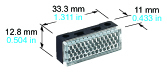
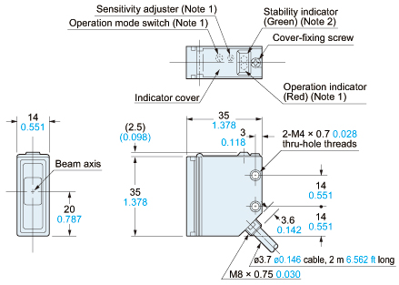
Dimensions
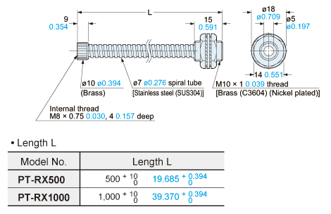
- Unit: mm in
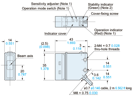
RX-M10
RX-M2R RX-500G RX2-M5
Sensor
Notes:1) Not incorporated on the emitter.2) It is the emitting indicator (red) on the emitter.
RX-M50
Sensor
Notes:1) Not incorporated on the emitter.2) It is the emitting indicator (red) on the emitter.
RX4-M5□
Sensor
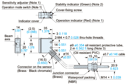
Notes:1) Not incorporated on the emitter.2) It is the emitting indicator (red) on the emitter.3) The given length of the protective tube is for RX4-M5-C3.(RX4-M5: 1 m3.281 ft, RX4-M5-C5: 4 m13.123 ft)
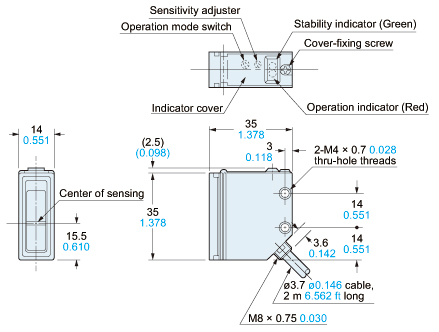
RX-RVM5
RX-PRVM3 RX-PRV500 RX2-PRVM2
Sensor
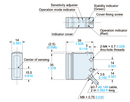
RX-D700
RX-D200R RX2-D300
Sensor
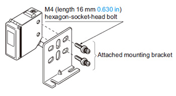
MS-RX-1
Sensor mounting bracket (Accessory for RX-□, RX2-□)
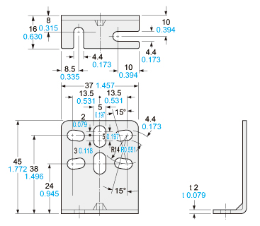
Material:Cold rolled carbon steel (SPCC)Two M4 (length 16 mm0.630 in) hexagon-socket-head bolts are attached.
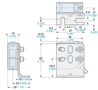
Assembly dimensions
Mounting drawing with RX-D700
MS-RX-2
Sensor mounting bracket (Accessory for RX4-□)
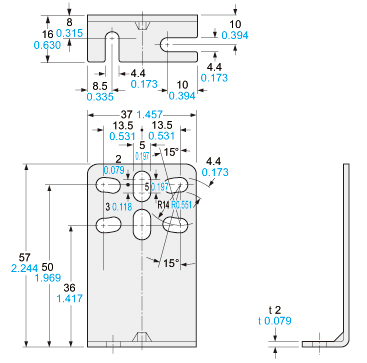
Material:Cold rolled carbon steel (SPCC)Two M4 (length 16 mm0.630 in) hexagon-socket-head bolts are attached.
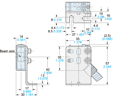
Assembly dimensions
Mounting drawing with RX4-M5
PT-RX500 PT-RX1000
Protective tube (Optional)
Reflector
Reflector mounting bracket
Refer to CX-400 series for dimensions of the reflector or the reflector mounting bracket.
I/O Circuit and Wiring diagrams
RX-□
RX4-□
I/O circuit diagrams
Emitter of thru-beam type sensor
Symbol・・・D : Reverse supply polarity protection diode
Wiring diagram
Emitter of thru-beam type sensor
*1
I/O circuit diagrams
Receiver of thru-beam type sensor
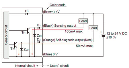
Note:The self-diagnosis output does not incorporate a short-circuit protection circuit. Do not connect it directly to a power supply or a capacitive load.
Symbols・・・
D1:Reverse supply polarity protection diode
D2,D3:Reverse output polarity protection diode
ZD1,ZD2:Surge absorption zener diode
Tr1,Tr2:NPN output transistor
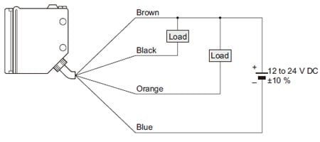
Wiring diagram
Receiver of thru-beam type sensor
I/O circuit diagrams
Retroreflective and diffuse reflective type sensors
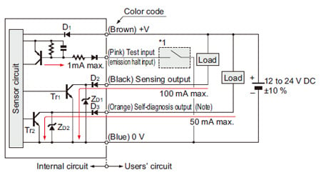
Note:The self-diagnosis output does not incorporate a short-circuit protection circuit. Do not connect it directly to a power supply or a capacitive load.
Symbols・・・
D1:Reverse supply polarity protection diode
D2,D3:Reverse output polarity protection diode
ZD1,ZD2:Surge absorption zener diode
Tr1,Tr2:NPN output transistor
Wiring diagram
Retroreflective and diffuse reflective type sensors
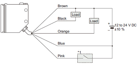
*1
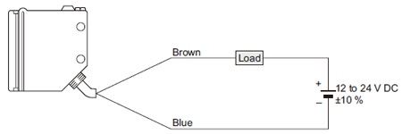
RX2-□
I/O circuit diagrams
Emitter of thru-beam type sensor
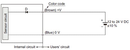
Symbol・・・D : Reverse supply polarity protection diode
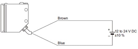
Wiring diagrams
Emitter of thru-beam type sensor
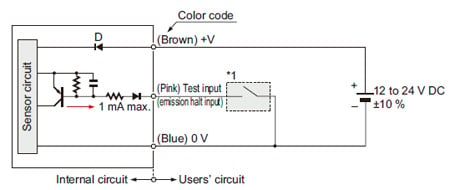
I/O circuit diagrams
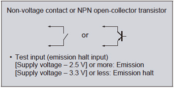
Receiver of thru-beam type sensor, retroreflective and diffuse reflective type sensors
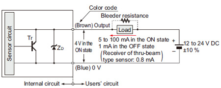
Symbols・・・D:Reverse supply polarity protection diodeZD:Surge absorption zener diodeTr:PNP output transistor
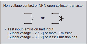
Conditions for the load
1)The load should not be actuated by the leakage current (1 mA; 0.8 mA for receiver of thru-beam type sensor) in the OFF state.
2)The load should be actuated by (supply voltage – 4 V) in the ON state.
3)The current in the ON state should be between 5 to 100 mA DC.
[In case the current is less than 5 mA, connect a bleeder resistance in parallel to the load (shown in dotted line above) so that a current of 5 mA, or more, flows.]
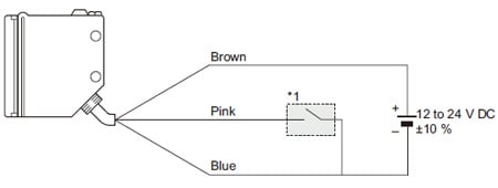
Wiring diagrams
Receiver of thru-beam type sensor, retroreflective and diffuse reflective type sensors
Sensing characteristics
*TYPICAL
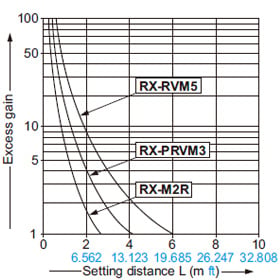
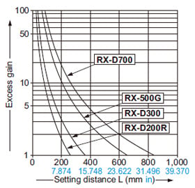
All models
Correlation between setting distance and excess gain
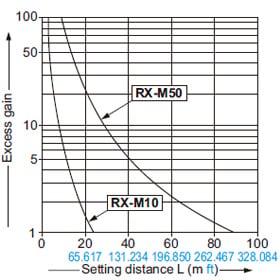
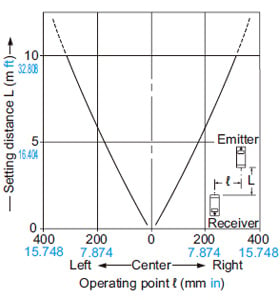
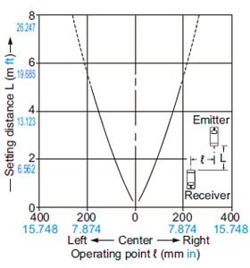
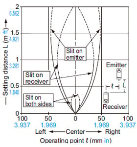
RX-M10
Thru-beam type
Parallel deviation
Parallel deviation with slit masks
(0.5 × 5 mm 0.020 × 0.197 in)
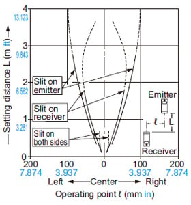
Parallel deviation with slit masks
(1 × 5 mm 0.039 × 0.197 in)
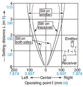
Parallel deviation with slit masks
(3 × 5 mm 0.118 × 0.197 in)
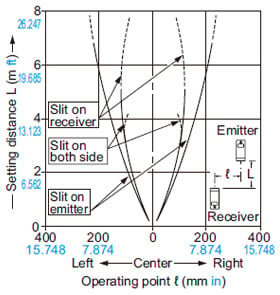
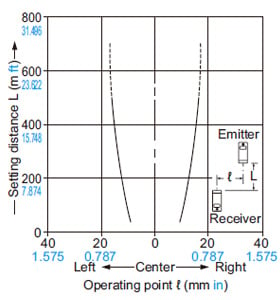
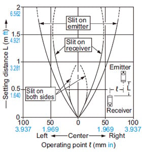
RX-M50
Thru-beam type
Parallel deviation
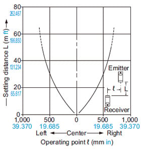
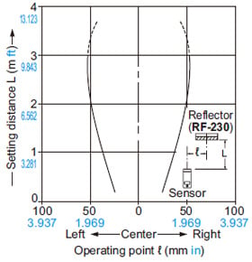
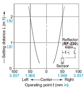
RX-RVM5
Retroreflective type
Parallel deviation
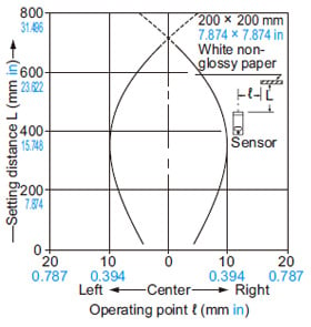
RX-D700
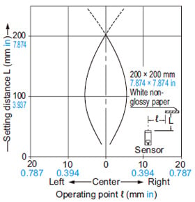
Diffuse reflective type
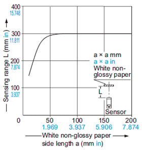
Sensing field
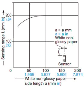
Correlation between sensing object size and sensing range
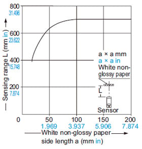
As the sensing object size becomes smaller than the standard size (white non-glossy paper 200 × 200 mm 7.874 × 7.874 in), the sensing range shortens, as shown in the left graph.
(For plotting the left graph, the sensitivity has been set such that a 200 × 200 mm 7.874 × 7.874 in white non-glossy paper is just detectable at a distance of 700 mm 27.559 in.)
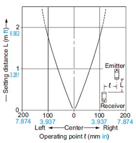
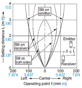
RX-M2R
Thru-beam type
Parallel deviation
RX-500G
Thru-beam type
Parallel deviation
RX4-M5□
Thru-beam type
Parallel deviation
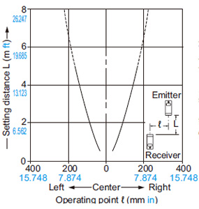
RX2-M5
Thru-beam type
Parallel deviation
Parallel deviation with slit masks
(0.5 × 5 mm 0.020 × 0.197 in)
Parallel deviation with slit masks
(1 × 5 mm 0.039 × 0.197 in)
Parallel deviation with slit masks
(3 × 5 mm 0.118 × 0.197 in)
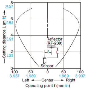
RX-PRVM3
Retroreflective type
Parallel deviation
RX2-PRVM2
Retroreflective type
Parallel deviation
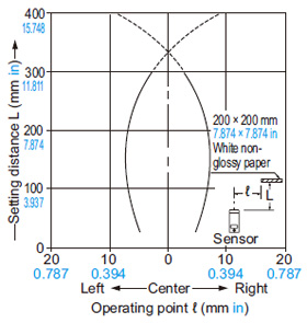
RX-D200R
Diffuse reflective type
Sensing field
Correlation between sensing object size and sensing range
As the sensing object size becomes smaller than the standard size (white non-glossy paper 200 × 200 mm 7.874 × 7.874 in), the sensing range shortens, as shown in the left graph.
(For plotting the left graph, the sensitivity has been set such that a 200 × 200 mm 7.874 × 7.874 in white non-glossy paper is just detectable at a distance of 200 mm 7.874 in.)
RX2-D300
Diffuse reflective type
Sensing field
Correlation between sensing object size and sensing range
As the sensing object size becomes smaller than the standard size (white non-glossy paper 200 × 200 mm 7.874 × 7.874 in), the sensing range shortens, as shown in the left graph.
(For plotting the left graph, the sensitivity has been set such that a 200 × 200 mm 7.874 × 7.874 in white non-glossy paper is just detectable at a distance of 300 mm 11.811 in.)
Wiring
- The self-diagnosis output does not incorporate a shortcircuit protection circuit. Do not connect it directly to a power supply or a capacitive load.
Mounting
- The tightening torque should be 1.17 N·m or less.
Others
- Do not use during the initial transient time (50 ms) after the power supply is switched on.
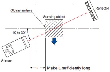
RX-RVM5
Glossy object sensing
- Please take care of the following points when detecting materials having a gloss.
[1] Make L, shown in the diagram, sufficiently long.
[2] Install at an angle of 10 to 30 degrees to the sensing object.
RX-PRVM3 RX2-PRVM2
Retroreflective type sensor with polarizing filters
Example of sensing objects
- If a shiny object is covered or wrapped with a transparent film such as those described below, the retroreflective type sensor with polarizing filters may not be able to detect it.
In that case, follow the steps given below.
- Can wrapped by clear film
- Aluminum sheet covered by plastic film
- Gold or silver color (specular) label or wrapping paper
Steps - Tilt the sensor with respect to the sensing object while fitting.
- Reduce the sensitivity.
- Increase the distance between the sensor and the sensing object.
RX2-□
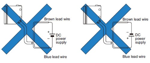
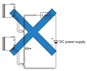
Wiring
- Always connect the sensor to the power supply through a load. If the sensor is connected to the power supply directly, the short-circuit protection makes the sensor inoperable. (The output stays in the OFF state and no indicator lights up.) If this happens, connect the sensor to the power supply through a load.
Further, note that the sensor will be damaged if the power supply is connected in reverse without a load.
- Do not connect sensors in series (AND circuit).
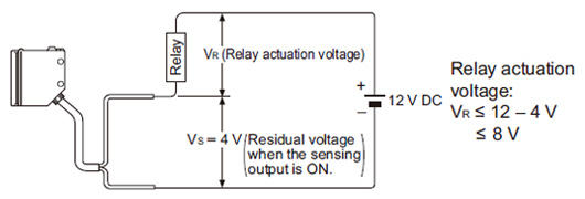
- The residual voltage of the sensor is 4 V. Before connecting to a relay, be aware of the actuation voltage of the relay.
(Not all 12 V relays may be connected as the load.)
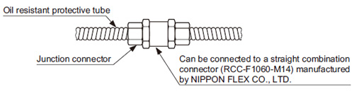
RX4-□
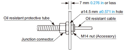
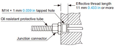
Connection of protective tube connector
- Connect the junction connector securely as shown below. The tightening torque should be 0.98 N·m or less.
When mounted on a plate
When mounted with a female screw
When connected to another protective tube