Basic Information
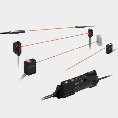
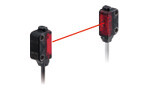
Industry’s smallest* laser sensor head
LASER CLASS 1


-
* Smallest amplifier-separated type laser sensor head as of March 2024 based on research conducted by our company
Features
Industry’s smallest* + Stainless steel (SUS) enclosure
* Amplifier-separated type laser sensor head as of March 2024, in-company survey
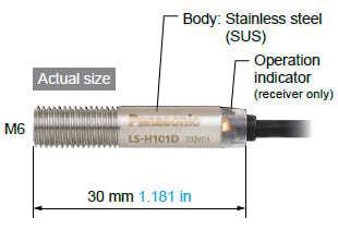
Stainless steel (SUS) body
Featuring stainless steel (SUS) enclosure that won't break when bumped during installation or maintenance.
One-point M6 installation
The LS-H101 features an easy-to-install design.
1 m 3.281 ft sensing range
(In STD amplifier response time mode)
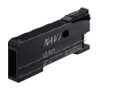
Industry’s smallest* + IP67* Amplifier
*Amplifier-separated type laser sensor head as of March 2024, in-company survey
Waterproof IP67
Featuring waterproof IP67 to allow use in the presence of large amounts of water or dust.
Simple positioning
Check the optimal receiving location at a glance while watching the red spot on the beam axis adjustment screen.
1 m 3.281 ft sensing range(In STD amplifier response time mode)
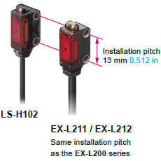
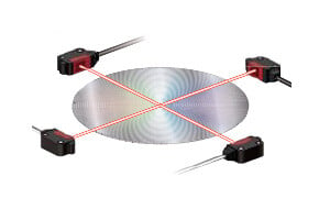
The LS-H102 delivers sufficient sensing range for use with 450 mm 17.717 in wafers.
Two-point installation
The thru-beam type LS-H102 features the same form as the EX-L200 amplifier built-in ultra-compact laser sensor. And it can be used as an EX-L200 with a digital indicator.
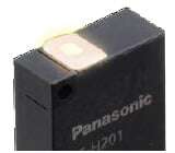
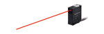
Industry’s smallest* + Thinnest profile
*Amplifier-separated type laser sensor head as of March 2024, in-company survey
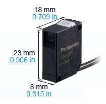
Featuring a 60% smaller design (by volume) than previous coaxial reflective models
Our smallest unit is smaller in every dimension at just W8 × H23 × D18 mm W0.315 × H0.906 × D0.709 in (excluding indicators).
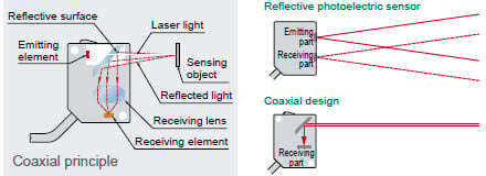
Coaxial design
By using a laser with high linearity in a coaxial design, the LS-H201 is able to deliver stable sensing in confined spaces as well as simple installation.
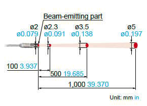
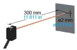
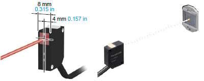
Small, long-range spot
The LS-H201 produces a spot with a diameter of 2 mm 0.079 in at a sensing range of up to 300 mm 11.811 in (in STD amplifier response time mode).
Easy-to-see operation indicator
The LS-H201’s operation indicator is visible from all directions.
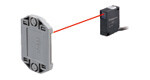
Industry’s smallest* + Horizontal symmetry
* Amplifier-separated type laser sensor head as of March 2024, in-company survey
Horizontal symmetry
Featuring a simple system design process thanks to a light source that is placed in the center of the sensor head and a coaxial design.
Industry’s smallest* and thinnest design
The LS-H901 is even thinner than previous models, measuring just W8 × H23 (excluding indicators) × D18 mm W0.315 × H0.906 × D0.709 in.
* Amplifier-separated type laser sensor head as of March 2024, in-company survey
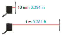
Sensing range of 10 mm to 1 m
0.394 in to 3.281 ft
(In STD amplifier response time mode)
The LS-H901 supports close-range sensing
Among industry's fastest response times* 60 μs
* Amplifier-separated type laser sensor head as of March 2024, in-company survey
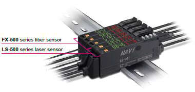
Maximum compatibility with fiber sensors
The LS-500 series features the same operation, menu displays, and form factor as the FX-500 series for increased compatibility with fiber sensors.
Detection of beam axis misalignment
Dual outputs (self-diagnosis output)
The LS-500 series can detect any reduction in incident light intensity, for example due to the accumulation of dirt such as dust, and issue an alarm. Sensing output 2 can be set as self-diagnosis output. When you teach the threshold for sensing output 1, sensing output 2 is set accordingly, allowing you to shift the threshold by a previously set margin.
Stable sensing over the long term
The LS-500’s threshold-tracking function helps maintain stable sensing over the long term and reduce maintenance man-hours. The incident light intensity can be checked and the threshold automatically reset at a user-selected interval to track changes in light intensity due to environmental changes (such as dust, etc.) over extended periods of time.
Logic operations
The LS-500’s ability to perform three logic operations (AND, OR, and XOR) on a standalone basis eliminates the need for a dedicated controller, cuts down on wiring, and lowers costs. This functionality can also be combined with the FX-500 series.
Data bank
Eight sets of amplifier settings can be stored in the unit’s built-in memory. The ability to save and load settings reduces workload when changing the setup in a multimodel production environment.
Network communication possible
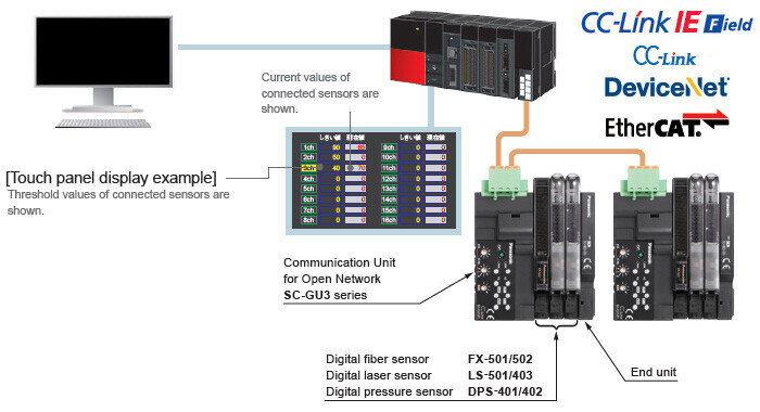
Can connect to Open Network CC-Link IE Field / CC-Link / EtherCAT via Communication Unit for Open Network SC-GU3 series. Monitoring and various settings can be done from PLC, PC, etc.
* CC-Link IE Field and CC-Link are trademarks of Mitsubishi Electric Corporation, and are controlled by the CC-Link Partner Association.
EtherCAT is a registered trademark of Beckhoff Automation GmbH.
* Refer to our website for details of each sensor.
Applications
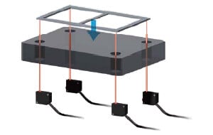
Lead frame position detection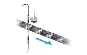
Order guide
Sensor heads
| Type | Appearance | Model No. | |
|---|---|---|---|
| Thru-beam type | Cylindrical |
| LS-H101 |
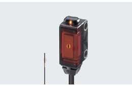
| Square |
| LS-H102 | |
| Coaxial reflective type |
| LS-H201 | |
| Coaxial retroreflective type |
| LS-H901 | |
5 m 16.404 ft cable length type
5 m 16.404 ft cable length types (Standard: 2 m 6.562 ft) are available. When ordering this type, suffix "-C5" to the model No.
Package without reflector
The LS-H901 is also available without a reflector (RF-330). When ordering this type, suffix "-Y" to the model No.
| Type | Standard type Model No. | 5 m 16.404 ft cable length type | Package without reflector | |
|---|---|---|---|---|
| Model No. | Model No. | |||
| Thru-beam type | Cylindrical | LS-H101 | LS-H101-C5 | - |
| Square | LS-H102 | LS-H102-C5 | - | |
| Coaxial reflective type | LS-H201 | LS-H201-C5 | - | |
| Coaxial retroreflective type | LS-H901 | LS-H901-C5 | LS-H901-Y | |
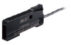
Amplifiers
| Type | Appearance | Model No. | Output | Connection method |
|---|---|---|---|---|
| Connector type |
| LS-501 | NPN open-collector transistor two outputs | Use quick-connection cable (optional) |
| LS-501P | PNP open-collector transistor two outputs | |||
| Cable type (With external input) |
| LS-501-C2 | NPN open-collector transistor two outputs | 2 m 6.562 ft cabtyre cable (6-core) included Cable outer diameter:ø4 mm ø0.157 in |
| LS-501P-C2 | PNP open-collector transistor two outputs |
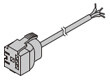
Quick-connection cables
Quick-connection cable is not supplied with the connector type amplifier. Please order it separately.
| Type | Appearance | Model No. | Description | |
|---|---|---|---|---|
| Main cable (4-core) |
| CN-74-C1 | Length: 1 m 3.281 ft | 0.2 mm2 4-core cabtyre cable, with connector on one end Cable outer diameter:ø3.3 mm ø0.130 in |
| CN-74-C2 | Length: 2 m 6.562 ft | |||
| CN-74-C5 | Length: 5 m 16.404 ft | |||
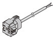
| Sub cable (2-core) |
| CN-72-C1 | Length: 1 m 3.281 ft | 0.2 mm2 2-core cabtyre cable, with connector on one end Cable outer diameter:ø3.3 mm ø0.130 in Connectable to a main cable up to 15 cables. |
| CN-72-C2 | Length: 2 m 6.562 ft | |||
| CN-72-C5 | Length: 5 m 16.404 ft | |||
Connector
| Type | Appearance | Model No. | Description |
|---|---|---|---|
| Connector for amplifier |
| CN-EP4 | Connector included with sensor head Use for maintenance, for example when another connector is damaged. Five pcs. per set |

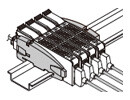
End plates
End plates are not supplied with the amplifier. Please order them separately when the amplifiers are mounted in cascade.
| Appearance | Model No. | Description |
|---|---|---|
| MS-DIN-E | When amplifiers are mounted in cascade, or when an amplifier moves depending on the way it is installed on a DIN rail, these end plates clamp amplifiers into place on both sides. Make sure to use end plates when cascading multiple amplifiers together. [Two pcs. per set] |
Accessories
MS-LS-1 (Sensor head mounting bracket): LS-H201□/LS-H901□
Material: Stainless steel SUS304Two M2 (length 12 mm0.472 in) screws with washers[stainless steel (SUS)] are attached.
RF-330 (Reflector)
MS-EXL2-2 (Mounting plate for thru-beam type)
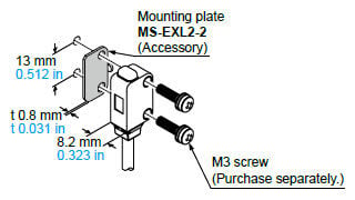
Material: Stainless steel (SUS304)
Option
| Designation | Model No. | Description | |
|---|---|---|---|
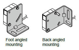
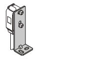
| Sensor head mounting bracket | MS-EXL2-1 | For LS-H102□ (square side sensing type) Foot angled mounting bracket | |
| MS-EXL2-4 | For LS-H102□ (square side sensing type) Universal sensor mounting bracket | ||
| MS-EXL2-5 | For LS-H102□ (square side sensing type) Back angled mounting bracket | ||
| Amplifier mounting bracket | MS-DIN-2 | Mounting bracket for amplifier | |
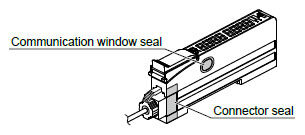
| Amplifier protective seal | FX-MB1 | 10 sets of 2 communication window seals and 1 connector seal Communication window seal: It prevents malfunction due to transmission signal from another amplifier, as well as, prevents effect on another amplifier. Connector seal: It prevents contact of any metal, etc., with the pins of the quick-connection cable. | |
| Reflector | RF-310 | For coaxial retroreflective type Compact reflector | Sensing range: 0.01 to 1m 0.033 to 3.281 ft |
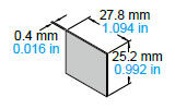
| Reflective tape | RF-31 | For coaxial retroreflective type Size: 9.2 × 9.2 × t 0.4 mm 0.362 × 0.362 × t 0.016 in | |
| RF-33 | For coaxial retroreflective type Size: 25.2 × 27.8 × t 0.4 mm 0.992 × 1.094 × t 0.016 in | Sensing range: Same as the RF-330. | |
Sensor head mounting bracket
・MS-EXL2-1
Material: Stainless steel (SUS304)Two M3 (length 14 mm0.551 in) screws with washers [stainless steel (SUS)] are attached.
・MS-EXL2-4
Material: Die-cast zinc alloyTwo M3 (length 14 mm0.551 in) screws with washers [stainless steel (SUS)], one M3 (length 10 mm0.394 in) hexagon-socket-head bolt [stainless steel (SUS)], and one M3 hexagon nut [stainless steel (SUS)] are attached.
・MS-EXL2-5
Material: Stainless steel (SUS304)Two M3 (length 14 mm0.551 in) screws with washers [stainless steel (SUS)] are attached.
Amplifier mounting bracket
・MS-DIN-2
Reflector
・RF-310
Reflective tape
・RF-33
・RF-31

Amplifier protective seal
・FX-MB1
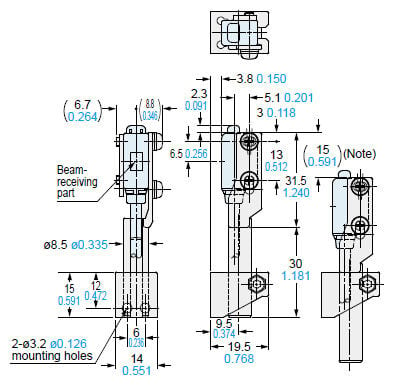
Dimensions
- Unit: mm in
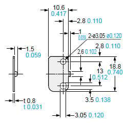
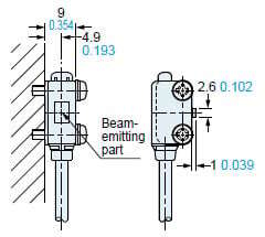
LS-H101□
Sensor head
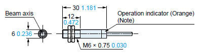
Note: Not incorporated on the emitter.
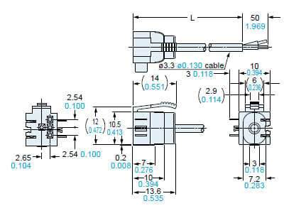
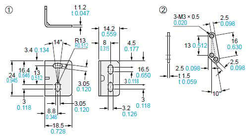
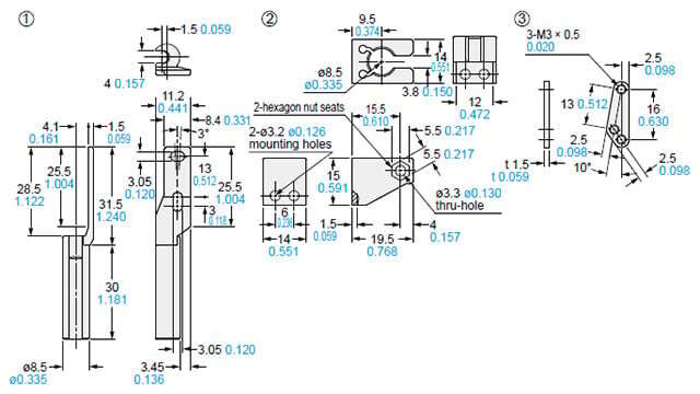
LS-H102□
Sensor head
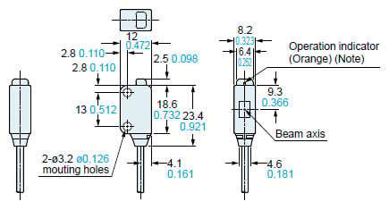
Note: Not incorporated on the emitter.
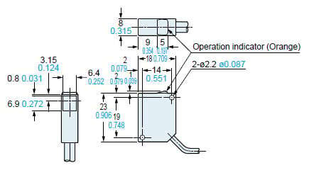
LS-H201□
LS-H901□
Sensor head
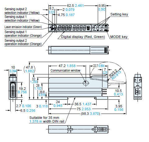
LS-501
LS-501P
Amplifier
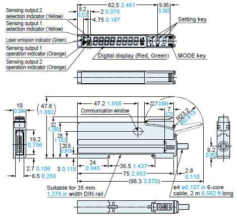
LS-501-C2
LS-501P-C2
Amplifier
CN-74-C1
CN-74-C2
CN-74-C5
Main cable (Optional)
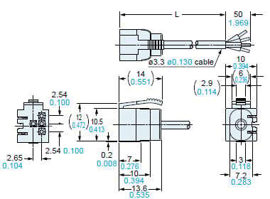
・Length (L)
| Model No. | Length (mm in) |
|---|---|
| CN-74-C1 | 1,000 39.370 |
| CN-74-C2 | 2,000 78.740 |
| CN-74-C5 | 5,000 196.850 |
CN-72-C1
CN-72-C2
CN-72-C5
Sub cable (Optional)
・ Length (L)
| Model No. | Length (mm in) |
|---|---|
| CN-72-C1 | 1,000 39.370 |
| CN-72-C2 | 2,000 78.740 |
| CN-72-C5 | 5,000 196.850 |
MS-DIN-E
End plate (Optional)
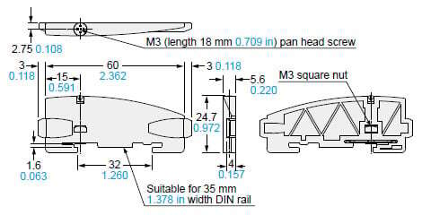
Material: Polycarbonate
RF-330
Reflector (Accessory for LS-H901□)
Material: Acrylic (Reflector), ABS (Base)
RF-310
Reflector (Optional)
Material: Acrylic (Reflector), ABS (Base)
RF-33
RF-31
Reflective tape (Optional)
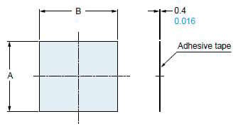
Material: Acrylic
| Model No. | A | B |
|---|---|---|
| RF-33 | 25.2 0.992 | 27.8 1.094 |
| RF-31 | 9.2 0.362 | 9.2 0.362 |
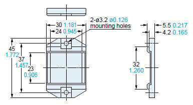
MS-DIN-2
Amplifier mounting bracket (Optional)
Material: Cold rolled carbon steel (SPCC) (Uni-chrome plated)
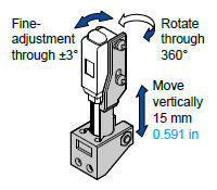
MS-LS-1
Sensor head mounting bracket (Accessory for LS-H201□, LS-H901□)
Material: Stainless steel (SUS304)Two M2 (length 12 mm0.472 in) screws with washers [stainless steel (SUS)] are attached.
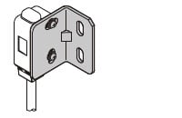
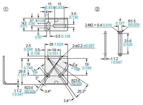
MS-EXL2-1
Sensor head mounting bracket for LS-H102□ (Optional)
Foot angled mounting bracket
Material: Stainless steel (SUS304)Two M3 (length 14 mm0.551 in) screws with washers [stainless steel (SUS)] are attached.
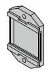
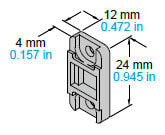
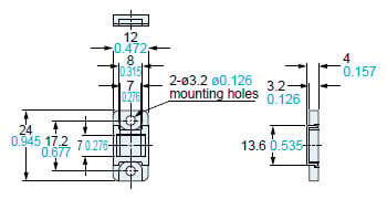
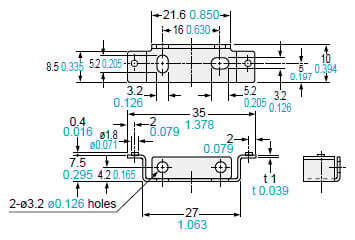
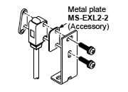
MS-EXL2-2
Mounting plate (Accessory for LS-H102□)
Material: Stainless steel (SUS304)Note: Screws are not attached. Purchase separately.
Assembly dimensions
Mounting drawing with the emitter of LS- H102□
Note: Without using the mounting plate, beam misalignment may occur.
MS-EXL2-5
Back angled mounting bracket
Material: Stainless steel (SUS304)Two M3 (length 14 mm0.551 in) screws with washers [stainless steel (SUS)] are attached.
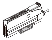
MS-EXL2-4
Sensor head mounting bracket for LS-H102□ (Optional)
Universal sensor mounting bracket
Material: Die-cast zinc alloyTwo M3 (length 14 mm0.551 in) screws with washers [stainless steel (SUS)], one M3 (length 10 mm0.394 in) hexagon-socket-head bolt [stainless steel (SUS)], and one M3 hexagon nut [stainless steel (SUS)] are attached.
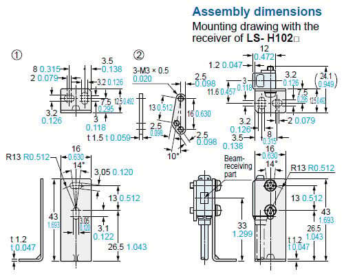
Assembly dimensions
Mounting drawing with the receiver of LS- H102□
Note: This is the adjustable range of the movable part.
I/O Circuit and Wiring diagrams
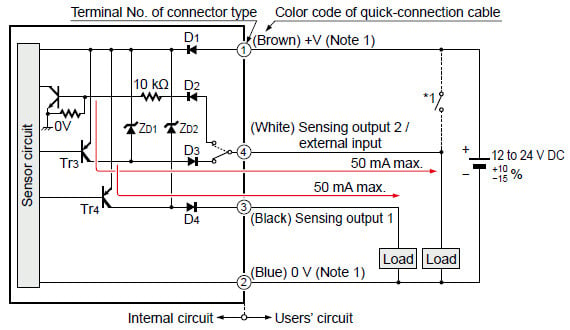
I/O circuit diagram NPN output type
Connector type
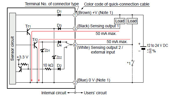
Notes:
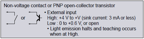
1)The quick-connection sub cable does not have +V (brown) and 0 V (blue).The power is supplied from the connector of the main cable.
2)Wiring when sensing output 2 is selected is shown with solid lines. Wiring when external input is selected is shown with broken lines.
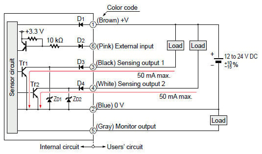
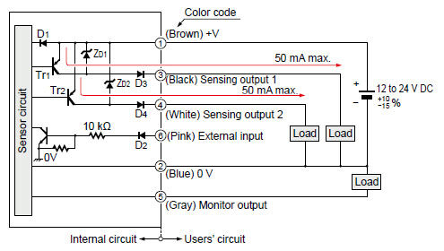
Cable type
*1
Symbols ...D1, D2, D3, D4: Reverse supply polarity protection diodeZD1, ZD2: Surge absorption zener diodeTr1, Tr2 : NPN output transistor
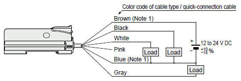
Wiring diagram
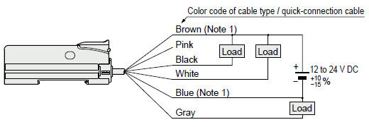
Notes:
1)The quick-connection sub cable does not have brown lead wire and blue lead wire. The power is supplied from the connector of the main cable.
2)The quick-connection cable does not have gray or pink lead wires.
Terminal layout of connector type
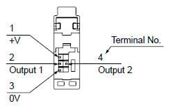
* Connector for amplifier (CN-EP4) pin position

| Terminal No. | Connection cable |
|---|---|
| 1 | Purple |
| 2 | White |
| 3 | Shield |
| 4 | Shield |
| 5 | Black |
| 6 | Pink |
I/O circuit diagram PNP output type
Connector type
Notes:
1)The quick-connection sub cable does not have +V (brown) and 0 V (blue).The power is supplied from the connector of the main cable.
2)Wiring when sensing output 2 is selected is shown with solid lines. Wiring when external input is selected is shown with broken lines.
Cable type
*1
Symbols...D1, D2, D3, D4:Reverse supply polarity protection diodeZD1, ZD2:Surge absorption zener diodeTr1, Tr2:PNP output transistor
Wiring diagram
Notes:
1)The quick-connection sub cable does not have brown lead wire and blue lead wire.The power is supplied from the connector of the main cable.
2)The quick-connection cable does not have gray or pink lead wires.
Terminal layout of connector type
* Connector for amplifier (CN-EP4) pin position
| Terminal No. | Connection cable |
|---|---|
| 1 | Purple |
| 2 | White |
| 3 | Shield |
| 4 | Shield |
| 5 | Black |
| 6 | Pink |
- This product is a class 1 laser product according to IEC/EN/JIS/GB/KS standards and FDA regulations*.
- Avoid observing beams in a dark surrounding environment.
- Do not look at beams using an optical device such as an optical telephoto system.
- The following label is affixed to the emitter of this product. Handle the product according to the instruction given on the label.

This product complies with the FDA regulations (FDA 21 CFR 1040.10 and 1040.11) in accordance with FDA Laser Notice No. 56, except for complying with IEC 60825-1 Ed. 3.
Safety standards for laser beam products
- For the purpose of preventing any injury which may occur to the user by the use of the laser product in advance, the following standards have been established by the IEC Standards, EN Standards, JIS Standards, GB Standards, KS Standards and FDA Regulations.
IEC : IEC 60825-1:2014
EN : EN 60825-1:2014/A11:2021
JIS : JIS C 6802:2014
GB : GB 7247.1-2012
KS : KS C IEC 60825-1:2014
FDA : PART 1040.10, 1040.11(Laser Notice No.56 applied)
These standards classifies laser products according to the level of hazard and provide the safety measures for respective classes. Based on the above standards, the LS-H□ series is classified as a Class 1 laser product.
| Classification | Description |
|---|---|
| Class 1 | Lasers that are safe under reasonably foreseeable conditions of operation, including the use of optical instruments for intrabeam viewing. |
Note: When an unexpected failure occurs, dangerous radiation may be generated. Therefore, pay special attention to safety.
Safe use of laser products
- For the purpose of preventing users from suffering injuries by laser products, each standard stipulates (Safety of laser products). Kindly check the standards before use.
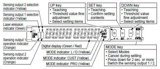
Part description (Amplifier)
Mounting
Amplifier
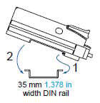
<How to mount the amplifier>
(1)Fit the rear part of the mounting section of the amplifier on a 35 mm 1.378 in width DIN rail.
(2)Press down the rear part of the mounting section of the unit on the 35 mm 1.378 in width DIN rail and fit the front part of the mounting section to the DIN rail.
<How to remove the amplifier>
(1)Push the amplifier forward.
(2)Lift up the front part of the amplifier to remove it.
Note:Be careful. If the front part is lifted without pushing the amplifier forward, the hook on the rear portion of the mounting section is likely to break.
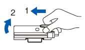
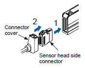
<How to mount the sensor head>
(1)Insert the sensor head connector into the inlet until it clicks.
(2)Fit the cover to the connector.
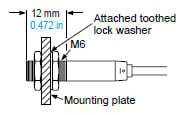
Sensor head:LS-H101□
- The tightening torque should be 0.98 N·m or less.
Sensor head:LS-H102□
- In case mounting this product, use a metal plate MS-EXL2-2 (accessory).
- The tightening torque should be 0.5 N·m or less with M3 screws.
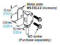
- In case using the dedicated sensor head mounting bracket MS-EXL2-1 (optional) when mounting this product, the metal plate MS-EXL2-2 (accessory) is required depending on the mounting direction. Mount as the diagram below indicates.
<Not requiring the metal plate>
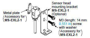
<Requiring the metal plate>
LS-H201□, LS-H901□
- The tightening torque should be 0.5 N・m or less.
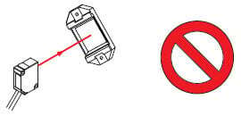
- When placing the sensor head horizontally or vertically, the reflector must also be positioned horizontally or vertically as shown in Fig. 1 below.
If the sensor head is placed horizontally or vertically but the reflector is tilted as shown in Fig. 2 below, the reflection amount will decrease, which may cause unstable detection.
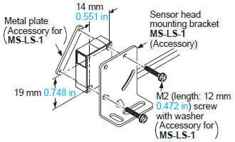
Fig. 1 Proper positioning
When placing the sensor head horizontally or vertically, the reflector shall also be positioned horizontally or vertically.
<Correct>
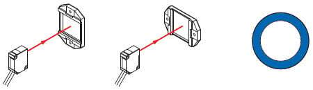
Fig. 2 Improper positioning
When placing the reflector tilted even when the sensor head is positioned horizontally or vertically.
<Incorrect>
Wiring
- Make sure that the power supply is off while wiring.
- Verify that the supply voltage variation is within the rating.
- Take care that if a voltage exceeding the rated range is applied, or if an AC power supply is directly connected, the sensor may get burnt or damaged.
- If power is supplied from a commercial switching regulator, ensure that the frame ground (F.G.) terminal of the power supply is connected to an actual ground.
- In case noise generating equipment (switching regulator, inverter motor, etc.) is used in the vicinity of this product, connect the frame ground (F.G.) terminal of the equipment to an actual ground.
- Take care that short-circuit or wrong wiring of the load may burn or damage the sensor
- Do not run the wires together with high-voltage lines or power lines or put them in the same raceway. This can cause malfunction due to induction.
- Ensure that an isolation transformer is utilized for the DC power supply. If an auto transformer is utilized, the main amplifier or power supply may be damaged.
- Make sure to use the optional quick-connection cable for the connection of the amplifier [connector type LS-501(P)]. Extension up to total 100 m 328.084 ft is possible with 0.3 mm2, or more, cable. However, in order to reduce noise, make the wiring as short as possible. Set the supply voltage after considering the voltage drop caused by the cable’s resistance. When adding units, wiring length must not exceed 50 m 164.042 ft (for 5 to 8 amplifiers) or 20 m 65.617 ft (for 9 to 16 amplifiers).
Others
- Do not use during the initial transient time (0.5 sec. approx.) after the power supply is switched on.
- Because the sensitivity is higher in U-LG and HYPER modes than in other modes, it can be more easily affected by extraneous noise. Check the operating environment before use.
- This sensor is suitable for indoor use only.
- Avoid dust, dirt, and steam.
- Take care that the product does not come in direct contact with water, oil, grease, or organic solvents, such as, thinner, etc.
- This sensor cannot be used in an environment containing inflammable or explosive gasses.
- Never disassemble or modify the sensor.