------------------------------ Tab1 showing ------------------------------
Basic Information
The laser distance sensor HG-F1 series features a lightweight and high-strength aluminum diecast case with a built-in TOF sensor module.
The sensor unit boasts a compact and robust body and offers a long-range sensing capability.


UL, CSA : Certified by TÜV SÜD America Inc.
Features
Comparison of product series
| Product name / series name | Model No. | Measurable range / Measurement center distance and Measurement range | Beam diameter (typical value) | Repeatability |
|---|---|---|---|---|
 HG-F series | HG-F1□ | 250 to 3,00 0 mm 9.843 to 118.11 in | Approx. ø10 mm ø0.394 in (at the measuring distance of 1,000 mm 39.370 in) | 10 mm 0.394 in or less |
| HG-C series | HG-C1030□ | 30±5 mm 1.181±0.197 in | Approx. ø50 μm ø1.969 mil | 10 μm 0.394 mil |
| HG-C1050□ | 50±15 mm 1.969±0.591 in | Approx. ø70 μm ø2.756 mil | 30 μm 1.181 mil | |
| HG-C1100□ | 100±35 mm 3.937±1.378 in | Approx. ø120 μm ø4.724 mil | 70 μm 2.756 mil | |
| HG-C1200□ | 200±80 mm 7.874±3.150 in | Approx. ø300 μm ø11.811 mil | 200 μm 7.874 mil | |
| HG-C1400□ | 400±200 mm 15.748±7.874 in | Approx. ø500 μm ø19.685 mil |
*The sensing object used for the HG-F1 series was a sheet of white non-glossy paper measuring 200 × 200 mm 7.874 in × 7.874 in and the sensing object used for the HG-C series was white ceramics.
*The beam diameter was defined as 1/e2 (approx. 13.5%) of the center light intensity.
It is the size at a measuring distance of 1,000 mm 39.370 in in the case of the HG-F1 series or at the measurement center distance in the case of the HG-C series.
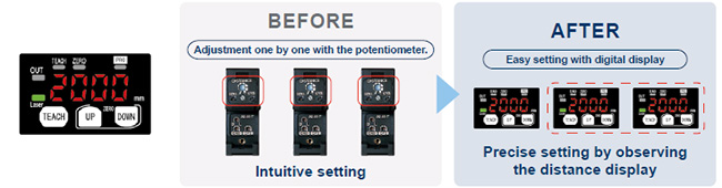
Distance measuring system ensures stable sensing.
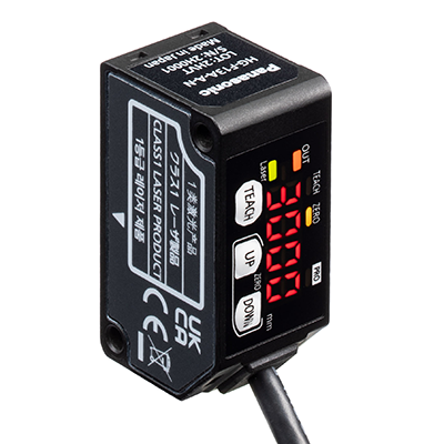
The product is equipped with a 7-segment display that indicates measured distances digitally in mm.
Quantification of detection states enables the setting of the most suitable threshold values consistently for anyone.
Digital display of measured distance
- Measured distance is displayed in mm.
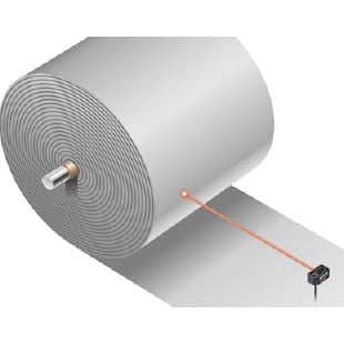
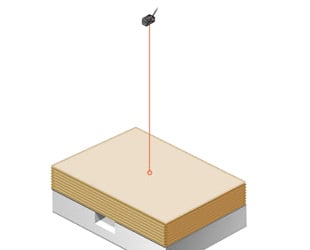
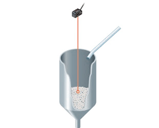
Measurement of distance to the workpiece
- Not easily affected by material or color.
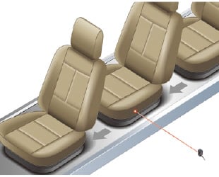
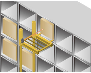
- Enables the confirmation of quantity of stacked objects and detects position.

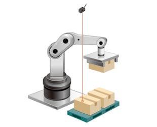
Confirmation of delivery of workpiece / quantity of stacked objects at transfer robot section
Analog output
- Measured values can be output to an external device (analog voltage: 0 to +5 V, analog current: +4 to +24 mA)
- The analog scaling setting enables the acquisition of data from a desired measurement range.
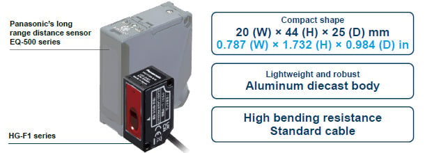
Compact and robust aluminum diecast body
The HG-F1 series sensor has been downsized by about 80% of the previous long range distance sensor model (EQ-500 series) by volume ratio.
The unit body is made of aluminum diecast so it is lightweight and robust.
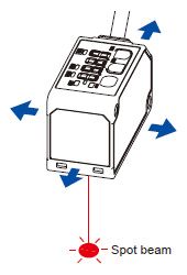
Selectable use of spot beam according to specific usage conditions
Emitted beam spot check mode
Work efficiency can be improved by selecting the most suitable spot beam type from the two options according to specific usage conditions. The spot beam emitted for measurement blends in with the surroundings to minimize the discomfort resulting from the laser that comes into the field of vision. During installation / adjustment, the emitted beam spot check mode allows clear recognition of the beam spot and enables the reliable confirmation of sensing position even in the case of long-distance sensing.
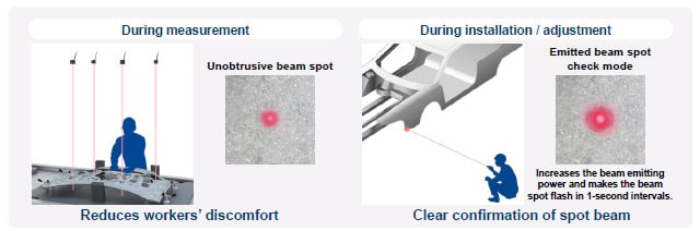
* The beam spot appears differently depending on the detected object’s material, surrounding conditions and distance.* When the emitted beam spot check mode is used, the distance to the detected object cannot be measured.
Visible light laser (Class 1) achieves pinpoint detection
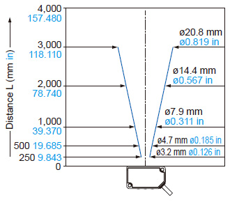
Narrow field sensing
The spot beam is smaller than that of a conventional adjustable-range distance sensor so that pinpoint detection is possible.
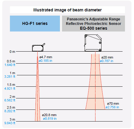
* The above beam diameters are typical values. Confirm the appropriateness of the beam diameter in actual installation condition.* The beam diameter may be affected by the materials of surrounding objects and their distances.* The typical beam diameter of the EQ-501 / EQ-511 is used as the diameter of the EQ-500 series.
------------------------------ Tab2 showing ------------------------------
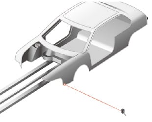
Applications
Shown above are application examples. Note that detection may not be possible in some cases due to the shapes, color, luster, etc. of the workpieces used by the customer. Be sure to confirm proper operation with actual machines. If the sensors fail to detect, consult our sales office in charge.
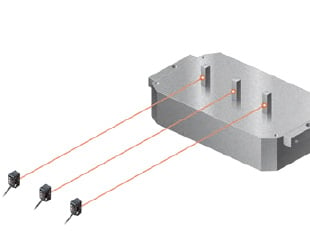
Confirmation of door parts installation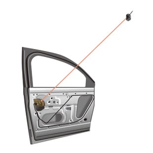
------------------------------ Tab3 showing ------------------------------
Order guide
Appearance
| Measurable range | Repeatability | Beam diameter (Note) | Model No. | |
|---|---|---|---|---|
| NPN output | PNP output | |||
| 250 mm to 3,000 mm 9.843 in to 118.110 in | 10 mm 0.394 in or less | Approx. ø10 mm ø0.394 in (typical) (at the measuring distance of 1,000 mm 39.370 in) | HG-F13A-A-N | HG-F13A-A-P |
Notes:
1)Value obtained using a sheet of white non-glossy paper measuring 200 × 200 mm 7.874 × 7.874 in
2)These values were defined by using 1/e2 (approx. 13.5%) of the center light intensity.
Due to leak light outside the defined range, the measurement values may be affected if the reflectance around the detecting point is higher than that of the detecting point.
------------------------------ Tab4 showing ------------------------------
Option
| Designation | Model No. | Description |
|---|---|---|
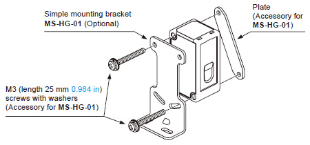
| Simple mounting bracket | MS-HG-01 | Foot angled mounting bracket |
Simple mounting bracket
MS-HG-01
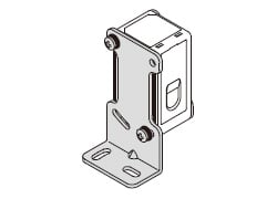
Material: Stainless steel (SUS304)Two M3 (length 25 mm0.984 in) screws with washers (SPCC) are attached.
------------------------------ Tab5 showing ------------------------------
------------------------------ Tab6 showing ------------------------------
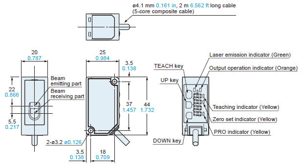
Dimensions
- Unit: mm in
HG-F13A-A-N
HG-F13A-A-P
Sensor
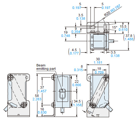
MS-HG-01
Simple mounting bracket (Optional)
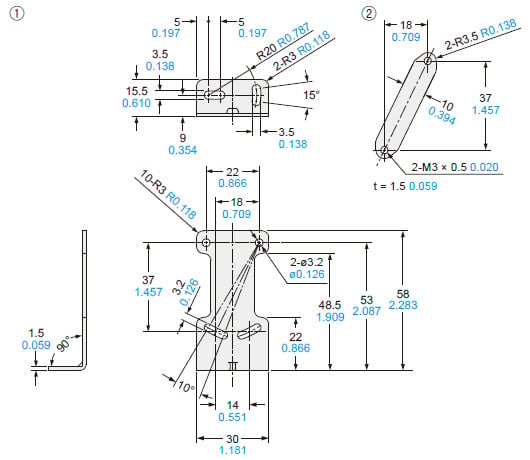
Material: Stainless steel (SUS304)Two M3 (length 25 mm0.984 in) screws with washers (SPCC) are attached.
Assembly dimensions
------------------------------ Tab7 showing ------------------------------
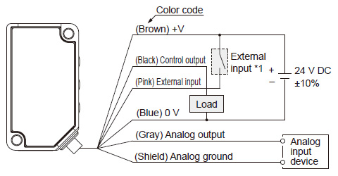
I/O Circuit and Wiring diagrams
HG-F13A-A-N
NPN output type
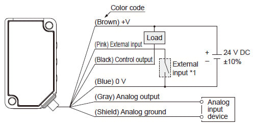
*1
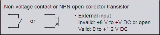
Note: Insulate the unused terminals in order to prevent input errors and short-circuits.
HG-F13A-A-P
PNP output type
*1
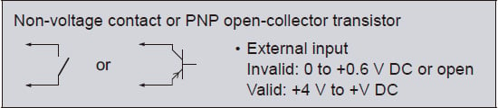
Note: Insulate the unused terminals in order to prevent input errors and short-circuits.
------------------------------ Tab8 showing ------------------------------
Sensing characteristics
(TYPICAL)
* Be sure to confirm proper condition in actual installation condition.
REPEATABILITY CHARACTERISTICS
Repeatability by sensing distance/by response time
| Measuring distance | White non-glossy paper | Gray non-glossy paper | ||||||
|---|---|---|---|---|---|---|---|---|
| Response time | Response time | |||||||
| 35 ms | 100 ms | 300 ms | 2,000 ms | 35 ms | 100 ms | 300 ms | 2,000 ms | |
| 250 mm 9.843 in | 5 mm 0.197 in | 5 mm 0.197 in | 3 mm 0.118 in | 1 mm 0.039 in | 6 mm 0.236 in | 6 mm 0.236 in | 3 mm 0.118 in | 1 mm 0.039 in |
| 500 mm 19.685 in | 6 mm 0.236 in | 5 mm 0.197 in | 3 mm 0.118 in | 1 mm 0.039 in | 6 mm 0.236 in | 7 mm 0.276 in | 3 mm 0.118 in | 1 mm 0.039 in |
| 1,000 mm 39.370 in | 7 mm 0.276 in | 6 mm 0.236 in | 3 mm 0.118 in | 2 mm 0.079 in | 7 mm 0.276 in | 7 mm 0.276 in | 5 mm 0.197 in | 2 mm 0.079 in |
| 2,000 mm 78.740 in | 7 mm 0.276 in | 6 mm 0.236 in | 3 mm 0.118 in | 3 mm 0.118 in | 14 mm 0.551 in | 7 mm 0.276 in | 5 mm 0.197 in | 3 mm 0.118 in |
| 3,000 mm 118.110 in | 7 mm 0.276 in | 6 mm 0.236 in | 4 mm 0.157 in | 3 mm 0.118 in | 23 mm 0.906 in | 12 mm 0.472 in | 9 mm 0.354 in | 4 mm 0.157 in |
*The above values were obtained using a sheet of white non-glossy paper measuring 200 × 200 mm 7.874 × 7.874 in (N9 to N9.5, reflectance: approx. 80%) or a sheet of gray non-glossy paper measuring 200 × 200 mm 7.874 × 7.874 in (N5, reflectance: approx. 20%).
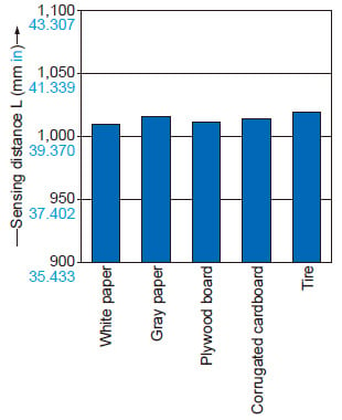
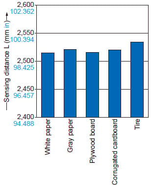
SENSING CHARACTERISTICS
Emitted beam characteristics
Correlation between material and sensing distance
Setting distance: 1,000 mm 39.370 in
Setting distance: 2,500 mm 98.425 in
------------------------------ Tab9 showing ------------------------------
- This product is a class 1 laser product according to IEC/EN/JIS/GB/KS standards and FDA regulations*.
- Avoid observing beams in a dark surrounding environment.
- Do not look at beams using an optical device such as an optical telephoto system.
- Never attempt to disassemble, repair, or modify this product.
- The following label is affixed to this product. Handle the product according to the instruction given on the label.
- When exporting this product to the United States of America attach the FDA certificate / identification label to the cable close to the sensing device.

*This product complies with the FDA regulations (FDA 21 CFR 1040.10 and 1040.11) in accordance with Laser Notice No. 56, except for the conformity with IEC 60825-1 Ed. 3.
Safety standards for laser beam products
- For the purpose of preventing any injury which may occur to the user by the use of the laser product in advance, the following standards have been established by the IEC Standards, EN Standards, JIS Standards, GB Standards, KS Standards and FDA Regulations.
IEC : IEC 60825-1:2014
EN : EN 60825-1:2014/A11:2021
JIS : JIS C 6802:2014
GB : GB 7247.1-2012
KS : KS C IEC 60825-1:2014
FDA : PART 1040.10, 1040.11(Laser Notice No.56 applied)
These standards classifies laser products according to the level of hazard and provide the safety measures for respective classes. Based on the above standards, the HG-F series is classified as a Class 1 laser product.
| Classification | Description |
|---|---|
| Class 1 | Lasers that are safe under reasonably foreseeable conditions of operation, including the use of optical instruments for intrabeam viewing. |
Note: When an unexpected failure occurs, dangerous radiation may be generated. Therefore, pay special attention to safety.
Safe use of laser products
- For the purpose of preventing users from suffering injuries by laser products, each standard stipulates (Safety of laser products).Kindly check the standards before use.
Part description
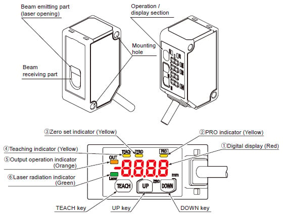
| No. | Name | Function1 |
|---|---|---|
| (1) | Digital display (Red) | Displays measured values and settings. |
| (2) | PRO indicator (Yellow) | Lit when PRO mode is set. |
| (3) | Zero set indicator (Yellow) | Lit while the zero set function is ON. |
| (4) | Teaching indicator (Yellow) | Lit while teaching is in progress |
| (5) | Output operation indicator (Orange) | Lit while control output is ON. |
| (6) | Laser radiation indicator (Green) | Lit while laser beams are being emitted. |
Emitted beam spot check method
- The emitted beam spot check mode is available to facilitate the confirmation of the laser beam spot position. When this mode is used, the beam spot becomes brighter and flashes.
Activate the emitted beam spot check mode by following the procedure described below and adjust the workpiece position.
(1)After turning ON the power, make sure that the display shows the following measurement screen. Then, press and hold the UP key for 3 seconds or longer.
The emitted beam spot check mode will be activated.
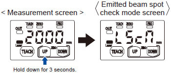
(2)The product emits a spot beam in 1-second intervals.
While observing the beam spot, move the sensor unit and adjust the optical axis.
・When the "emitted beam spot check mode" is used, sensing objects cannot be measured.
・By holding down the UP key for 3 seconds or longer while the "emitted beam spot check mode" is selected, you can return to the measurement display.
・The display automatically returns to the measurement display when 2 minutes elapse after the sensor is set to the "emitted beam spot check mode". To continue to adjust the beam axis, hold down the UP key for 3 seconds or longer again to set the "emitted beam spot check mode".
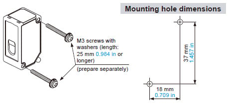
Installation
- When mounting the sensor unit, use M3 screws with washers (length: 25 mm 0.984 in or longer) (not included with the product).
The tightening torque should not exceed 0.5 N∙m.
・When using multiple sensors, mount them so that emitted laser beams do not directly enter the beam receiving parts of other sensors in order to avoid mutual interference. Also, mount them so that spot beams irradiated on a workpiece do not overlap with those of other sensors.
・Do not mount the sensors closely side by side to prevent heat generation. Otherwise, the product temperature may exceed the specified temperature due to heat generation.
・To prevent the product from falling due to loose screws, take prevention measures such as using screws with washers depending on the operating environment.
- Use the tightening torque of 0.5 N∙m or less when using the simple mounting bracket MS-HG-01 (optional).
Power supply
- Verify that the supply voltage fluctuations are within the rating when using the product. Note that applying a voltage greater than the rated voltage or directly applying AC power will result in damage or burning.
- To ensure performance, use the product at least 30 minutes (warm-up time) after the power is turned ON.
- If power is supplied from a commercial switching regulator, ensure that the frame ground (F.G.) terminal of the power supply is connected to an actual ground.
- Make sure that the power supply input satisfies the following items.
1)The power supply unit must be certified for use in your region
2)The output holding time of the power supply unit must be 20 ms or more
3)The rated output voltage and ripple (P-P) of the power supply unit must be 24 V DC ±10% and 10% or lower, respectively.
4)The power supply unit with SELV (Safety Extra Low Voltage) or PELV (Protective Extra Low Voltage) that comply with the EMC Directive must be used (if the CE marking compliance is required).
5)The power supply unit with SELV (Safety Extra Low Voltage) or PELV (Protective Extra Low Voltage) that comply with the EMC Regulations must be used (if the UKCA marking compliance is required).
6)The power supply unit must support Class 2 (if cTÜVus marking compliance is required).
- If surges occur, take countermeasures such as connecting a surge absorber to the source of the surges.
- Do not turn OFF the power while conducting teaching or saving settings such as the PRO mode setting. Doing so can damage the internal memory of the product and may disable the product from restarting.
Wiring
- Before wiring work, always turn the power OFF.
- Do not wire in parallel with a high-voltage line or power line, or run through the same conduit. Doing so may result in malfunctioning due to induction.
- Apply a load so that a current of 50 mA or more does not flow through the control output line. Also avoid incorrect wiring such as polarity connection error of the power supply. Failure to do so may cause damage or burning.
- The overall length of the cable can be extended to 10 m 32.808 ft maximum with a cable size of 0.3 mm2 or more. Use a shielded cable to extend the analog wire line.
- Do not apply stress such as excessive bending or pulling to the extracted part of a cable.
Operating environment
- This product is suitable for indoor use only.
- Do not install the sensor in the following locations.
・Locations subject to flammable gas, corrosive gas, or excessive dust
・Locations subject to dust, metal particles, or saline matter
・Atmospheres containing benzine, paint thinner, alcohol, or other organic solvents or strong alkaline substances such as ammonia or caustic soda
・Locations subject to severe vibration or shock
・Locations subject to direct sunlight
・Locations subject to water, oil, or chemicals
・Locations where load is applied to the sensor
- Avoid using this product in environments where condensation occurs due to sudden temperature change.
- Performance may not be satisfactory in a strong electromagnetic field.
- Although it depends on the product type, lights from rapid start type or high frequency lighting type fluorescent lamps, sunlight, etc. may affect the sensing performance. Do not allow those lights to directly enter the emitting / receiving surfaces of the product.
- Keep the light emitting and receiving windows of this product clean and free of water, oil, fingerprints, and other substances that refract light as well as dust, grit, and other objects that intercept light. When cleaning the surfaces, wipe them with a lint-free soft cloth or lens cleaning paper.
- Make sure to turn OFF the power supply before cleaning the light emitting and receiving windows of this product.
- This product is a precision device. Do not drop or otherwise subject to shock. Doing so may cause product failure.
- Due to the detection principle, if there is a background object in a specific region, a distance different from the actual distance may be displayed. Confirm actual operations in an actual operating environment.
If an object exists in a particular zone, shield the laser within 24 m 78.740 ft.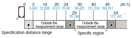
Others
- This product has been developed / produced for industrial use only.
- Do not use this product outside the scope of the specifications.
Doing so may result in accidents or failures. It will also significantly shorten the service life. - There is a certain deviation in the directivity of this product. When using this product, install the product using a mounting bracket or similar fitting to allow the adjustment of beam axis.
- The internal memory (non-volatile memory) of this product has a service life. Settings cannot be configured more than one million times.
- Due to leak light around the detection point, the measurement values may be affected if there exist objects with high reflectance around the detecting point.
- If specular reflection light enters the beam receiving part, proper measurement may not be possible. When the reflectance of a detection object is high, be careful in installation.
- When this product becomes unusable or unnecessary, dispose of the product properly as industrial waste in accordance with the applicable law in the country.