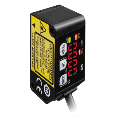
Basic Information
Reliable detection in repeatability 10 μm 0.394 mil*
* HG-C1030□


* This product complies with 21 CFR 1040.10 and 1040.11 Laser Notice No. 50, dated June 24, 2007, issued by CDRH (Center for Devices and Radiological Health) under the FDA (Food and Drug Administration).
Features
Equipped with 0 to 5 V analog output and 4 to 20 mA analog current output
The value can be measured with a distance measurement sensor.
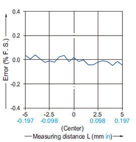
・ Linearity:±0.1%F.S.*1
・ Temperature characteristics:0.03 %F.S./℃
*1 : HG-C1030(-P)/HG-C1050(-P)/HG-C1100(-P)
<Compact>
The smallest CMOS laser sensor in the industry*
*Based on research conducted by our company as of July 2022
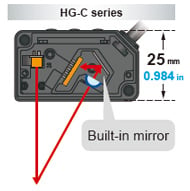
A new optical system with a built-in mirror
In general, more accurate and stable measurements can be obtained by increasing the optical path length between the light-receiving part and the light receiving element (CMOS), but this also increases the sensor depth and the sensor body gets bigger. The HG-C series sensors incorporating a new optical system with a built-in mirror provides smaller sensor depth as well as higher measurement accuracy equivalent to displacement sensors.
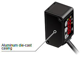
An aluminum die-cast casing protects from strain and heat
A light-weight but strong die-cast aluminum casing has been adopted. A compact, solid body casing reduces the impact of strain and heat on the measurement accuracy.
<Overwhelmingly stable>
Precise measurements on the order of 1/100 mm 0.0003 inch*
* HG-C1030□
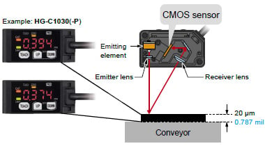
Fitted with a precise CMOS image sensor and an original algorithm
Thanks to a precise CMOS image sensor, it is now possible to perform highly precise measurements in the order of 1/100 mm 0.0003 in. The existing adjustable range reflective sensors cannot achieve such accuracy.
Useful functions
Teaching & window comparator mode
Normal sensing mode
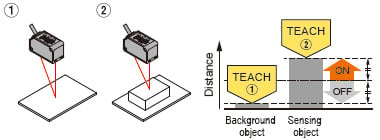
[2-Point teaching]
Basic teaching method
The threshold value is set automatically at the midpoint between the two points specified by teaching.
[Limit teaching]
Useful teaching method for when there is a very small object or background object.
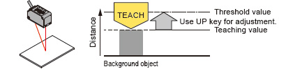
<When using background object as reference>
When the sensing object is located closer to the sensor than the background object, the threshold value for detection is set. This function is useful when there is a change in the size of sensing object.
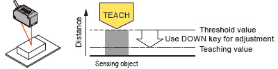
<When using sensing object as reference>
The threshold value is set on the background object side with reference to the sensing object. Use this method when there is a long distance to the background object.
Window comparator mode
With an object below the sensor, press the TEACH key to set the valid range for distances via threshold values. There are 3 methods for setting the valid range: 1-point, 2-point, and 3-point teaching.
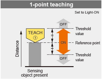
Perform 1-point teaching and the threshold range is set for the distance from the reference surface of the sensing object.
This is used for sensing within the threshold range.
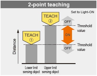
Press TEACH once for the lower (first point) and once for the upper limit (second point).
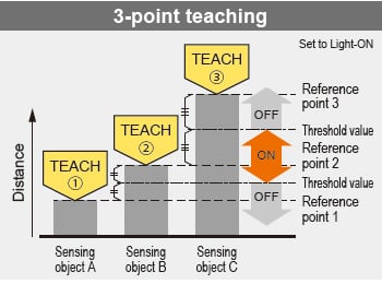
This is the method to set the threshold range by conducting the teaching at 3 points (sensing object A, B and C). After teaching, the reference points are automatically sorted in ascending order (reference point 1, 2 and 3). The thresholds are set at the midpoints between reference point 1 and 2, and 2 and 3, respectively.
Rising differential mode / Trailing differential mode
Use this mode to cancel gradual changes in the measured value and to detect only sudden changes. For the setting of threshold value, use the threshold value fine adjustment function.
Timer setting function
The time mode options are “off-delay timer,” “on-delay timer,” “one-shot timer” and “no timer.” The counting time is fixed to 5 ms.
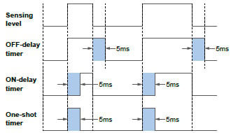
Timer period: 5 ms (fixed)
Off-delay timer
Function : Extends output signals by 5 ms.
Usage : Appropriate in case a connected device is slow to respond and ON time is required to extend.
On-delay timer
Function: Overrides output signals for 5 ms after detection.
Usage: Convenient way to override temporary signals and control with a time lag.
One-shot timer
Function: Sends output signals for only 5 ms after detection.
Usage: Useful when the signal duration needs to be constant to meet inputs from a connected device.
This mode is also used to extend temporary signals by a desired length of time.
Zero set function
This function compulsorily sets the measured value to “zero.”
The zero point can be set at a desired value. It is useful when measuring steps or tolerance with reference to the height of a sensing object.
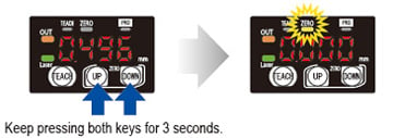
* The zero set indicator (yellow) will turn ON while the zero set is valid.* When the zero set function is executed while the peak hold function or the bottom hold function is valid, the held measurement value is reset.* When the display setting is set to offset, the zero set function cannot be set.
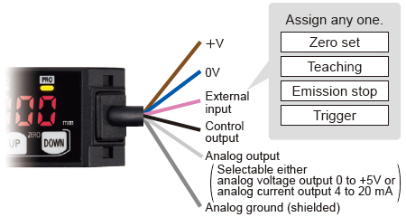
External input setting function
One of four functions, “zero setting function,” “teaching function,” “emission stopping function” and “trigger function” can be assigned to an external input line.
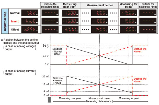
Display setting function
How to indicate measured values of the moving sensed object can be chosen from three options, “Normal,” “Invert” and “Offset.”
Example:HG-C1050(-P)
Peak and bottom hold functions
The peak hold function holds the maximum measured value which is output and displayed.
The bottom hold function holds the minimum measured value which is output and displayed.
* The peak hold function and the bottom hold function cannot be set at the same time.
* When the zero set function is executed while the peak hold function or the bottom hold function is valid, the held measurement value is reset.
Threshold value fine adjustment function
Fine adjustment of threshold values can be performed while measurement is proceeding on the display, and even after teaching.
Key lock function
This function protects setting conditions from unintentional changes.
* For other functions and procedures for setting the functions, see the instruction manual of the product.
Applications
Indicates real measurements
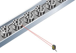
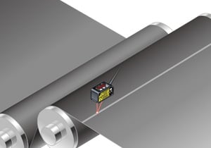
Measuring the hoop slack
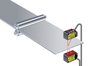
* If there is no workpiece between the sensors, avoid interference light by stopping the light emitting.
Compact and light-weight
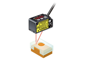
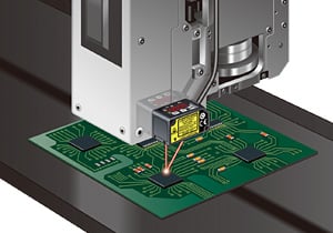
Controlling the dispenser head height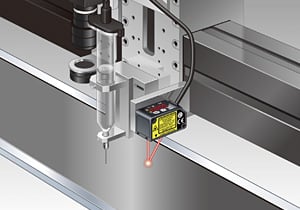
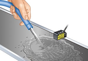
*Remove water droplets on detection surface to achieve correct measurement.
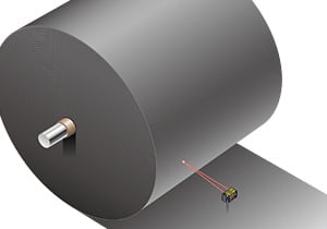
Long distance measurement
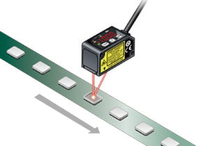
Detecting on-vehicle seats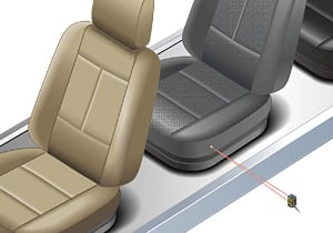
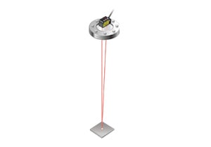
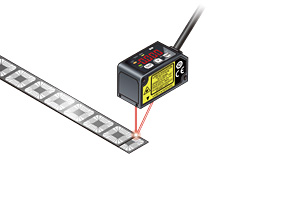
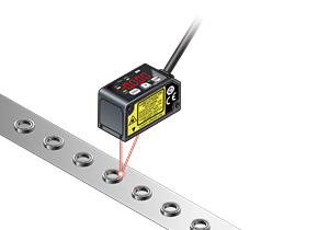
Excellent level detection performance
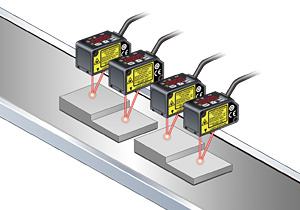
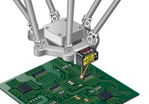
Detecting warpage of a circuit board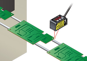
Order guide
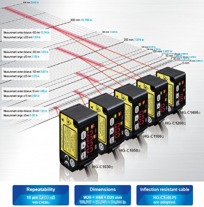
| Type | Appearance | Measurement center distance and measurement range | Repeatability | Beam diameter (Note) | Model No. | |
|---|---|---|---|---|---|---|
| NPN output | PNP output | |||||
| Measurement center 30mm 1.181 in type |
| 30±5mm 1.181 ± 0.197 in | 10μm 0.394 mil | ø50μm 1.969 mil approx. | HG-C1030 | HG-C1030-P |
| Measurement center 50mm 1.969 in type | 50±15mm 1.969 ± 0.591 in | 30μm 1.181 mil | ø70μm 2.756 mil approx. | HG-C1050 | HG-C1050-P | |
| Measurement center 100mm 3.937 in type | 100±35mm 3.937 ± 1.328 in | 70μm 2.756 mil | ø120μm 4.724 mil approx. | HG-C1100 | HG-C1100-P | |
| Measurement center 200mm 7.874 in type | 200±80mm 7.874 ± 3.150 in | 200μm 7.874 mil | ø300μm 11.811 mil approx. | HG-C1200 | HG-C1200-P | |
| Measurement center 400mm 15.748 in type | 400±200mm 15.748 ± 7.874 in | 300 μm 11.811 mil (Measuring distance 200 to 400 mm 7.874 to 15.748 in) 800 μm 31.496 mil (Measuring distance 400 to 600 mm 15.748 to 23.622 in) | ø500μm 19.685 mil approx. | HG-C1400 | HG-C1400-P | |

Note:
This is the size in the measurement center distance. These values were defined by using 1/e2 (13.5% approx.) of the center light intensity.
Due to leak light outside the specified area, the reflectance around the detecting point may be higher than at the point and this may affect the measurement value.
Option
| Designation | Model No. | Description |
|---|---|---|
| Simple mounting bracket (Note) | MS-HG-01 | Foot angled mounting bracket |
Note:
Due to the simple mounting bracket, the sensing characteristics may not be hold depending on the installation condition, in case of the purposes for acquiring the displacement data and a fine detecting.
Simple mounting bracket
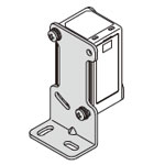
Material: Stainless steel (SUS304)Two M3 (length 25 mm0.984 in) screws with washers (SPCC) are attached.
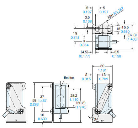
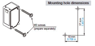
Dimensions
- Unit: mm in
HG-C□
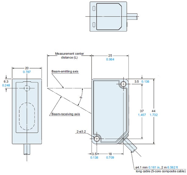
| Model No. | Measurement center distance (L) | θ |
|---|---|---|
| HG-C1030(-P) | 30 1.181 | 30° |
| HG-C1050(-P) | 50 1.969 | 22.5° |
| HG-C1100(-P) | 100 3.937 | 12.5° |
| HG-C1200(-P) | 200 7.874 | 6.3° |
| HG-C1400(-P) | 400 15.748 | 3.2° |
MS-HG-01
Simple mounting bracket (Optional)
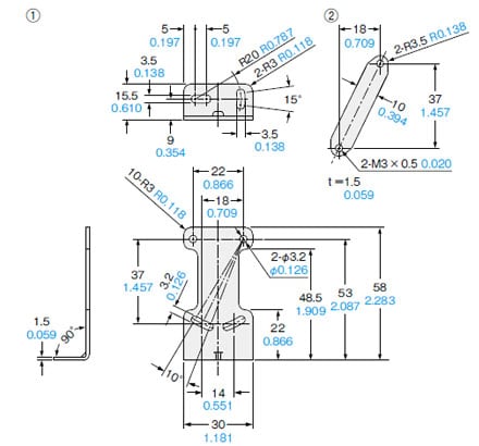
Material: Stainless steel (SUS304)Two M3 (length 25 mm0.984 in) screws with washers (SPCC) are attached.
Assembly dimensions
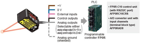
I/O Circuit and Wiring diagrams
HG-C1□0
NPN output Type
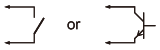
Non-voltage contact or NPN open-collector transistor
・External input
Invalid: +8 V to +V DC or open
Valid: 0 to +1.2 V DC
HG-C1□0-P
PNP output Type
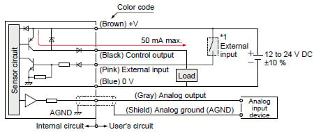
Non-voltage contact or PNP open-collector transistor
・External input
Invalid: 0 to +0.6 V DC or open
Valid: +4 V to +V DC
Sensing characteristics
Linearity
*TYPICAL
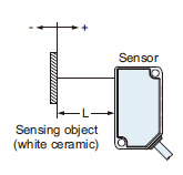
HG-C1030(-P)
HG-C1050(-P)
HG-C1100(-P)
HG-C1200(-P)
HG-C1400(-P)
- This product is a class 2 laser product according to IEC/EN/JIS/GB/KS standards and
FDA regulations *. - Avoid observing beams continuously, particularly in a dark surrounding environment.
- Do not look at beams using an optical device such as an optical telephoto system.
- Never attempt to disassemble, repair, or modify this product.
- A warning label according to IEC (EN) standards is affixed to this product, and warning labels according to JIS, GB, and KS standards are included with it. Remove the IEC (EN) warning label, and then affix an appropriate label to the product as needed.
- When exporting this product to the United States of America attach the FDA certificate / identification label to the cable close to the sensing device.

*This product complies with the FDA regulations (FDA 21 CFR 1040.10 and 1040.11) in accordance with FDA Laser Notice No. 56, except for complying with IEC 60825-1 Ed. 3.
Safety standards for laser beam products
- For the purpose of preventing any injury which may occur to the user by the use of the laser product in advance, the following standards have been established by the IEC Standards, EN Standards, JIS Standards, GB Standards, KS Standards and FDA Regulations.
IEC : IEC 60825-1:2014
EN : EN 60825-1:2014/A11:2021
JIS : JIS C 6802:2014
GB : GB 7247.1-2012
KS : KS C IEC 60825-1:2014
FDA : PART 1040.10, 1040.11(Laser Notice No.56 applied)
These standards classifies laser products according to the level of hazard and provide the safety measures for respective classes. Based on the above standards, HG-C series is classified as a Class 2 laser product.
・Explanation of hazard levels| Classification | Summary of hazard evaluation |
|---|---|
| Class 2 | A laser that emits visible light with the wavelength range of 400 nm to 700 nm under which eyes can be protected by an aversive reaction (Avoidance behavior) such as a blink. |
Note: When an unexpected failure occurs, dangerous radiation may be generated. Therefore, pay special attention to safety.
Safe use of laser products
- For the purpose of preventing users from suffering injuries by laser products, each standard stipulates (Safety of laser products). Kindly check the standards before use.
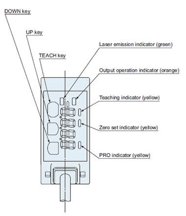
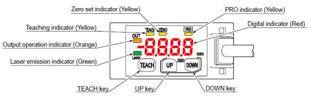
Part description
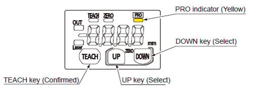
PRO mode setting
Part description
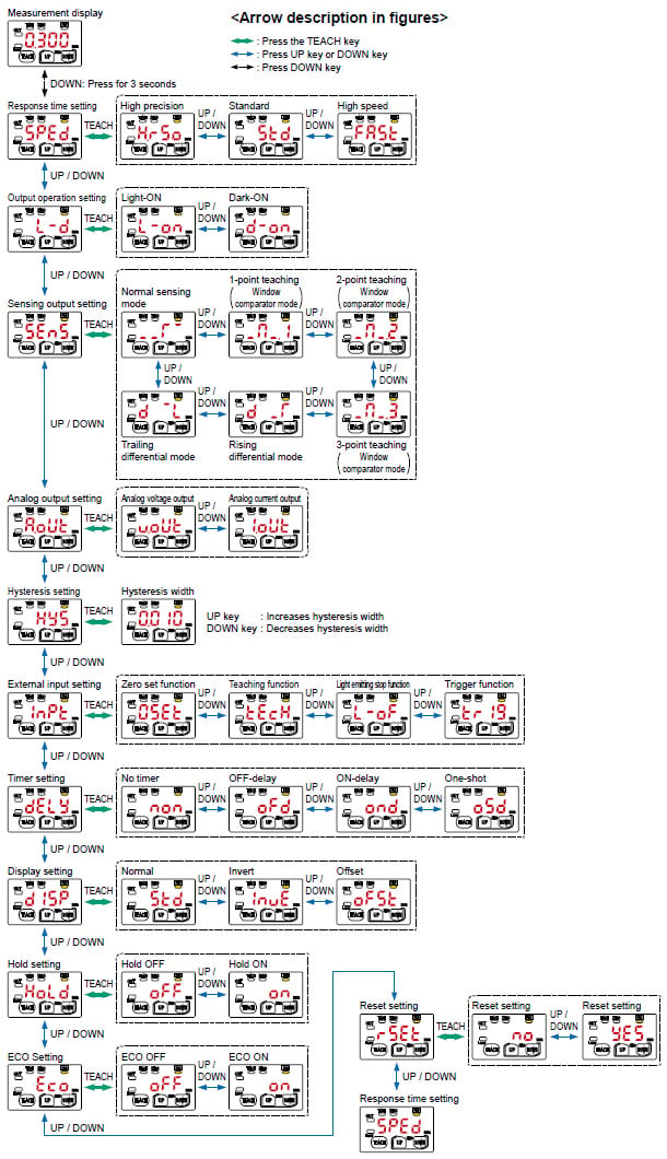
| Item | Default setting | Description |
|---|---|---|
| Response time setting |
| Set the response time.
|
| Output operation setting |
| Select the control output operation mode.
|
| Sensing output setting |
| Set the sensing output.
|
| Analog output setting |
| Sets the output operation of analog output setting.
|
| Hysteresis setting |
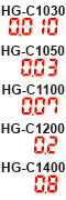
| Set the hysteresis width. HG-C1030 : 0.001 to 5.00mm 0.00004 to 0.197 in HG-C1050 : 0.01 to 15.00mm 0.00039 to 0.591 in HG-C1100 : 0.02 to 35.00mm 0.00079 to 1.378 in HG-C1200 : 0.1 to 80.0 mm 0.00394 to 3.150 in HG-C1400 : 0.2 to 200.0 mm 0.00787 to 7.874 in |
| External input setting |
| Set the external input.
|
| Timer setting |
| Set the timer operation. The timer time is fixed at 5ms.
|
| Display setting |
| The display of the measured value can be changed.
|
| Hold setting |
| Set the control output and the analogue output operation when a measurement error occurs (insufficient light intensity, saturation of light intensity, out of measurement range).
|
| ECO setting |
| The digital display can be set to go OFF when key operation is not performed for 30 seconds. Current consumption can be reduced.
|
| Reset setting |
| Return to the default setting (factory setting).
|


Procedure
Mounting
- When mounting this product, use M3 screws.
The tightening torque should be 0.5 N・m.
Please prepare M3 screws separately.
- When mounting the simple mounting bracket (optional) on this product, the tightening torque should be 0.5 N・m or less.
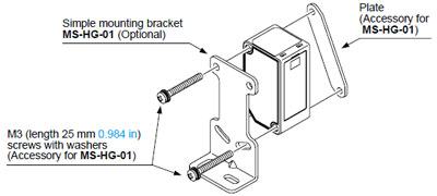
Note:
Due to the simple mounting bracket, the sensing characteristics may not be hold depending on the installation condition, in case of the purposes for acquiring the displacement data and a fine detecting.
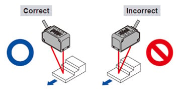
Mounting direction
- Direction to a movable body
- When performing measurements of moving objects with excessively different materials and colors, mount the product per the following directions to minimize measurement errors.
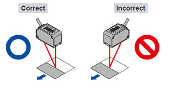
- When measuring rotating objects, mount the product as follows. Measurement can be performed with minimized effect on the object caused by up / down deflection, position deviation and etc.
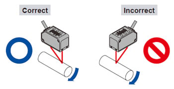
- When there is a step in the moving object, mount the product as follows. Measurement can be performed with minimized effect from the edges of the steps.
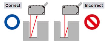
- Measuring of narrow locations and recesses
- When measuring in narrow locations or inside holes, mount the product so that optical path from the lightemitting part to light-receiving part is not interrupted.
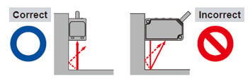
- When mounting the product on a wall
- Mount the product as follows, so that the multiple light reflections on the wall do not emit to the light-receiving part. When the reflection factor on a wall is high, it is effective to use a dull black color.
Others
- This product has been developed / produced for industrial use only.
- Make sure that the power supply is OFF before starting the wiring.
- If the wiring is performed incorrectly, it will cause a failure.
- Do not run the wires together with high-voltage lines or power lines, or put them in the same raceway. This can cause malfunction due to induction.
- Verify that the supply voltage variation is within the rating.
- If power is supplied from a commercial switching regulator, ensure that the frame ground (F.G.) terminal of the power supply is connected to an actual ground.
- If noise generating devices (switching regulators, inverter motors, etc.) are used around the sensor mounting area, make sure to connect the frame ground (FG) terminal of the device.
- Do not use this product during the transient state when the power supply is turned ON.
- The overall length of the cable can be extended to 10 m 32.808 ft maximum (HG-C1000L series: 20 m 65.617 ft maximum) with a cable size of 0.3 mm2 or more.
- Make sure that stress by forcible bend or pulling is not applied to the sensor cable joint.
- Although it depends on the type, light from rapid start type or high frequency lighting type fluorescent lights, sunlight and etc. may affect the sensing, therefore make sure to prevent direct incident light.
- This product is suitable for indoor use only.
- Keep water, oil, fingerprints and etc. which reflect light, or dust, particles or etc. which interrupts the light, away from the emitting / receiving surfaces of this product.
If contaminants adhere to the surface, wipe off with a dust-free soft cloth, or lens cleaning paper. - Do not use the sensor in locations where there is excessive vapor, dust or etc. or in an atmosphere where corrosive gases, etc. is generated.
- Take care that the product does not come in contact with oil, grease, organic solvents such as thinner, etc., strong acid or alkaline.
- Make sure to turn OFF the power supply, before cleaning the light emitting / receiving windows of the sensor head.
- There is a certain deviation in the directionality of this product. Install the product using a mounting bracket or similar fitting to allow the adjustment of optical axis.
- The internal memory (nonvolatile) of this product has a service life. Settings cannot be configured more than 100,000 times.
Error indication
・In case of errors, attempt the following measures.
| Error indication | Description | Remedy |
|---|---|---|
| Insufficient amount of reflected light. The sensing object is out of the sensing range. | Confirm that the sensing distance is within the specification range. Adjust the installation angle of the sensor. |
| Flash memory is damaged or is past its life expectancy. | Please contact our office. |
| Load of the sensing output is short-circuited causing an over-current to flow. | Turn OFF the power and check the load. |
| The semiconductor laser is damaged or is past its life expectancy. | Please contact our office. |
| ・When zero set is set, the measurement is not performed normally. ・Since the display setting is set to “Offset”, the zero set function can not be used. | ・Confirm that the sensing distance is within the specification range. ・Set the display to any setting except “Offset.” |
| During teaching, the measurement is not performed normally. | Confirm that the sensing distance is within the specification range. |
| System error | Please contact our office. |