Basic Information
The use of a safe LED light beam now allows for high precision detection with a resolution of 30 μm 1.181 mil


Features
No safety measures are required at all
As a safe red LED is used as the light source, there is no need for time-consuming safety measures. The protective covers usually required when using laser beams are not needed, and FDA approval is not required in order to use this sensor in the US.
Easy installation
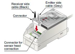
This unit is equipped with a one-touch connector to connect the sensor head to the controller. The amount of wiring is therefore minimized, resulting in easy maintenance.
Low current consumption of 70 mA or less
The HD-T1 series has a maximum current consumption of only 70 mA, for both the sensor head and the controller. The current consumption is almost as low as that of photoelectric sensors.
High resolution of 30 μm 1.181 mil
Although the HD-T1 series uses a red LED for its light source, it has the same high level of performance as laser sensors, thus enabling high precision detection.
No need for beam axis alignment
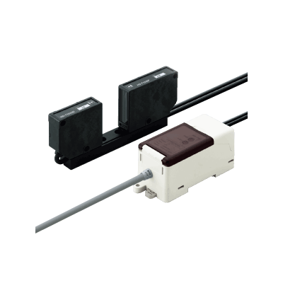
As both the receiver and the emitter are integrated into a single unit, there is no need to perform any troublesome alignment of the beam axis. In addition, as the HD-T1 series can perform its detection function over a broad area - with both a sensing range and a sensing width of 30 mm 1.181 in, this unit can be utilized for sensing wafers of many different sizes.
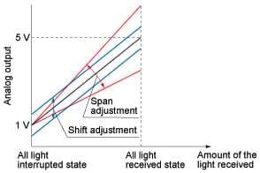
Adjustment functions for both span and shift have been incorporated
In addition to the span adjustment function, a convenient shift adjustment function has also been incorporated into the analog output (1 to 5 V). The shift adjustment function allows the analog voltage to be shifted by up to ±0.5 V.
Applications
Detecting wafer eccentricities or notches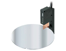
Order guide
Sensor head
| Appearance | Sensing range | Sensing width | Model No. |
|---|---|---|---|
| 30 mm 1.181 in (fixed) (Note) | 30 mm 1.181 in | HD-T1030 |

Note :
The value is in a state that the sensor is mounted on the mounting base at the time of factory shipment.
Controller
Make sure to use the sensor head and the controller together as a set.
| Appearance | Model No. | Output |
|---|---|---|
| HD-T1C | Analog voltage ・Output voltage: 1 to 5 V |

Dimensions
- Unit: mm in
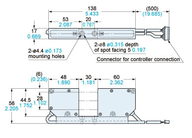
HD-T1030
Sensor head
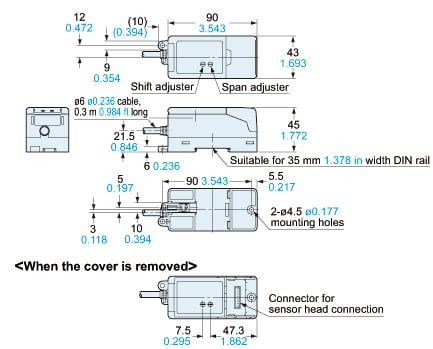
HD-T1C
Controller
I/O Circuit and Wiring diagrams
I/O circuit diagram
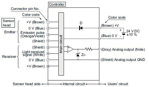
Note:Analog output does not incorporate a short-circuit protection circuit.Do not connect it directly to a power supply or a capacity load.
Symbols・・・
D:Reverse supply polarity protection diode
ZD:Surge absorption zener diode
Terminal arrangement
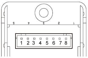
| Terminal No. | Description | |
|---|---|---|
| 1 | +V | Emitter side |
| 2 | 0V | |
| 3 | Emission pulse | |
| 4 | Shield | |
| 5 | Shield | Receiver side |
| 6 | Light received signal | |
| 7 | 0V | |
| 8 | +V | |
・Make sure to use the sensor head and the controller together as a set.
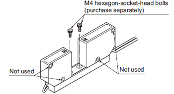
Mounting
- Mount the sensor head using 2 pcs. M4 hexagon-sockethead bolts (purchase separately) with a tightening torque of 0.5 N·m or less.
- Do not remove the screws fixing the emitter / receiver and the mounting base. If removed, the output value will change.
- Do not fix with the screws, using the mounting hole on the side of emitter / receiver.
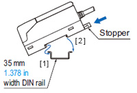
Controller
<In case of using DIN rail>
[1]Fit the front part of the mounting section of the unit on the 35 mm 1.378 in width DIN rail, pressing the stopper towards the arrow (the stopper is locked) shown in the right figure.
[2]Press down the rear part of the mounting section of the unit on the 35 mm 1.378 in width DIN rail to fit it.
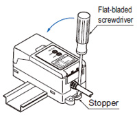
* For removal, insert a flat-bladed screwdriver into the groove of the stopper and pull the handle backwards.
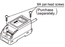
<In case of using screws>
- Mount using M4 pan head screws with a tightening torque of 1.2 N·m or less.
Wiring
- Analog output of controller does not incorporate a shortcircuit protection circuit. Do not connect it directly to a power supply or a capacity load.
- Care should be taken that static electricity is not applied to the connector during wiring. It may damage the product.
- Take care that wrong wiring will damage the product.
- Cable extension is possible up to total 3 m 9.843 ft with 0.3 mm2, or more, cable. Note that the cable length of the sensor head cannot be changed.
- Do not apply stress such as forced bending and pulling to the cable joint.
- Make sure to use an isolation transformer for the DC power supply. If an autotransformer (single winding transformer) is used, this product or the power supply may get damaged.
- In case a surge is generated in the used power supply, connect a surge absorber to the supply and absorb the surge.
Others
- Do not use during the initial transient time (0.5 sec. approx.) after the power supply is switched on.
- This product outputs according to the amount of LED light received. Optical power varies between the center and the periphery of sensing range, and note that dimensional accuracy cannot be assured.
- Do not allow any water, oil, fingerprints, etc., which may refract light, or dust, dirt, etc., which may block light, to stick to the emitting / receiving surfaces of the sensor head. In case they are present, wipe them with a clean, dust-free soft cloth or lens paper.
- If the sensing object is specular or transparent object, note that accurate measurement may not be possible.