------------------------------ Tab1 showing ------------------------------
Basic Information
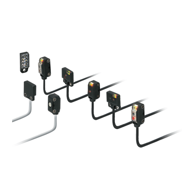
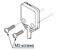
Miniature-sized and still mountable with M3 screws


UL : Recognition(Excluding 5 m cable length type)
Features
Miniaturization by using single chip optical IC
The beam-receiving photodiode and the A/D conversion circuit have been fabricated on a single chip optical IC (full custom). Hence, in spite of its miniature size, it has a performance and reliability which is equal to or better than the conventional product.
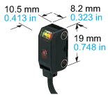
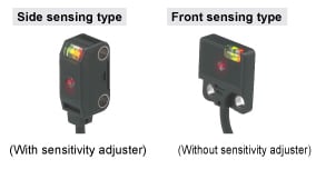
Incorporates a sensitivity adjuster even in this size
The sensor incorporates a sensitivity adjuster in spite of its miniature size. It is convenient when you need fine adjustment. Further, the receiver of the thru-beam, side sensing type sensor incorporates an operation mode switch which can change the output operation.
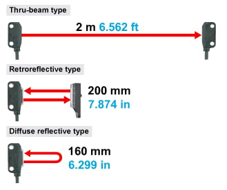
Long sensing range
The EX-20 series achieves long distance sensing [thru-beam type: 2 m 6.562 ft, retroreflective type: 200 mm 7.874 in (when using the attached reflector), diffuse reflective type: 160 mm 6.299 in], despite its miniature size.
Hence, it is usable even on a wide conveyor.
Clear beam spot using red LED dot light source
The emission area of a dot light source is smaller than that of a conventional LED flat light source, and it is possible to design a high power, narrow beam. Since a red LED dot light source is used, the red beam spot is clear even at a far place, so that alignment and confirmation of sensing position is easy. Further, since the thru-beam type, too, incorporates a visible narrow beam, it can also reliably detect small parts, such as, chip components, lead frames, etc.
Electric power saving
The EX-20 series achieves reductions in power consumption of up to 65 %.
These sensors contribute to environmental friendliness.

Waterproof IP67 (IEC)
The sensors features an IP67 rating to allow their use in process lines where water is used or splashed. Rust-resistant stainless steel sensor mounting brackets are available.
Note:If water splashes on the sensor during sensing operation, it may sense water as an object.
Incorporated an inverter countermeasure circuit
The EX-20 series become significantly stronger against inverter light and other extraneous light.
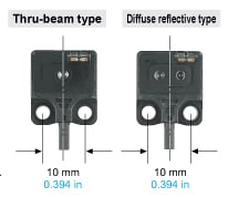
Identical size
Front sensing type of thru-beam type and diffuse reflective type sensors have identical appearance.
Moreover, since the mounting holes are symmetrical with respect to the beam axis center, the design becomes easy.
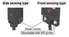
Mounting section reinforced
It can be tightened with M3 screws. Moreover, metal inserts have been provided in the mounting holes so that the product is not damaged even in case of excess tightening.
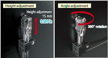
Universal sensor mounting bracket is available
Universal sensor mounting bracket MS-EXL2-4 (for EX-22/23/26/28/29□) and MS-EX20-5 (for EX-23□ only) which can freely adjust the height and the angle of the sensor is available.
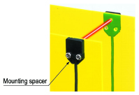
Mounting spacer for front sensing type is available
Mounting of the front sensing type is possible from the rear side by using the mounting spacer.
Slit mask is available
ø0.5 mm ø0.020 in round slit mask and 0.5 x 3 mm 0.020 x 0.118 in rectangular slit mask are available for both side sensing type and front sensing type sensors.
FUNCTIONS
Bright 2-color indicator
A bright 2-color indicator has been incorporated in all types. (Orange LED: Operation indicator, Green LED: Stability indicator)
Two types for suitable mounting
Two types, side sensing type and front sensing type sensors are available. Select depending on the place of mounting.
------------------------------ Tab2 showing ------------------------------
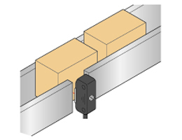
Applications
Detecting presence of chip components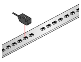


------------------------------ Tab3 showing ------------------------------
Order guide
| Type | Appearance | Sensing range | Model No. (Note 3) | Output | Output operation | ||
|---|---|---|---|---|---|---|---|
| Thru-beam | Front sensing |
| 1 m 3.281 ft | EX-21A | NPN open-collector transistor | Light-ON | |
| EX-21A-PN | PNP open-collector transistor | ||||||
| EX-21B | NPN open-collector transistor | Dark-ON | |||||
| EX-21B-PN | PNP open-collector transistor | ||||||
| Side sensing |
| 2 m 6.562 ft | EX-23 | NPN open-collector transistor | Switchable either Light-ON or Dark-ON | ||
| EX-23-PN | PNP open-collector transistor | ||||||
| Retroreflective | Side sensing |
| 30 to 200 mm 1.181 to 7.874 in (Note 1) | EX-29A | NPN open-collector transistor | Light-ON | |
| EX-29A-PN | PNP open-collector transistor | ||||||
| EX-29B | NPN open-collector transistor | Dark-ON | |||||
| EX-29B-PN | PNP open-collector transistor | ||||||
| Diffuse reflective | Side sensing |
| 5 to 160 mm 0.197 to 6.299 in (Note 2) | EX-22A | NPN open-collector transistor | Light-ON | |
| EX-22A-PN | PNP open-collector transistor | ||||||
| EX-22B | NPN open-collector transistor | Dark-ON | |||||
| EX-22B-PN | PNP open-collector transistor | ||||||
| Convergent reflective | Diffused beam type | Front sensing |
| 2 to 25 mm 0.079 to 0.984 in (Convergent point: 10 mm 0.394 in) | EX-24A | NPN open-collector transistor | Light-ON |
| EX-24A-PN | PNP open-collector transistor | ||||||
| EX-24B | NPN open-collector transistor | Dark-ON | |||||
| EX-24B-PN | PNP open-collector transistor | ||||||
| Small spot beam type | Side sensing |
| 6 to 14 mm 0.236 to 0.551 in (Convergent point: 10 mm 0.394 in) | EX-26A | NPN open-collector transistor | Light-ON | |
| EX-26A-PN | PNP open-collector transistor | ||||||
| EX-26B | NPN open-collector transistor | Dark-ON | |||||
| EX-26B-PN | PNP open-collector transistor | ||||||
| Narrow-view reflective | Long distance spot beam type | Side sensing |
| 45 to 115 mm 1.772 to 4.528 in | EX-28A | NPN open-collector transistor | Light-ON |
| EX-28A-PN | PNP open-collector transistor | ||||||
| EX-28B | NPN open-collector transistor | Dark-ON | |||||
| EX-28B-PN | PNP open-collector transistor | ||||||

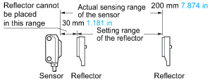
Note 1 :
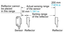
The sensing range of the retroreflective type sensor is specified for the RF-200 reflector.
Further, the sensing range is the possible setting range for the reflector.
The sensor can detect an object less than 30 mm 1.181 in away.
However, if the reflector is set 100 mm 3.937 in or less away, the sensing object should be opaque.
Note 2 :
In case of using this product at a sensing range of 50 mm 1.969 in or less, take care that the sensitivity adjustment range becomes extremely narrow.
Note 3 :
The model No. with "P" shown on the label affixed to the thru-beam type sensor is the emitter, "D" shown on the label is the receiver.
(e.g.) Emitter of EX-21A: EX-21P, Receiver of EX-21A: EX-21AD
Package without reflector
Retroreflective type is also available without the reflector RF-200.
When ordering this type, suffix "-Y" to the model No.
(e.g.) Without reflector type of EX-29A-PN is "EX-29A-PN-Y".
| Standard type | Package without reflector |
|---|---|
| EX-29A | EX-29A-Y |
| EX-29A-PN | EX-29A-PN-Y |
| EX-29B | EX-29B-Y |
| EX-29B-PN | EX-29B-PN-Y |
5 m 16.404 ft cable length type
5 m 16.404 ft cable length type (standard: 2 m 6.562 ft) is also available for NPN output type (including package without reflector of retroreflective type sensor).
When ordering this type, suffix "-C5" to the model No.
(e.g.) 5 m 16.404 ft cable length type of EX-29A-Y is "EX-29A-Y-C5".
| Standard type | 5 m 16.404 ft cable length type |
|---|---|
| EX-21A | EX-21A-C5 |
| EX-21B | EX-21B-C5 |
| EX-23 | EX-23-C5 |
| EX-29A | EX-29A-C5 |
| EX-29B | EX-29B-C5 |
| EX-29A-Y | EX-29A-Y-C5 |
| EX-29B-Y | EX-29B-Y-C5 |
| EX-22A | EX-22A-C5 |
| EX-22B | EX-22B-C5 |
| EX-24A | EX-24A-C5 |
| EX-24B | EX-24B-C5 |
| EX-26A | EX-26A-C5 |
| EX-26B | EX-26B-C5 |
| EX-28A | EX-28A-C5 |
| EX-28B | EX-28B-C5 |
Accessory
RF-200 (Reflector)
------------------------------ Tab4 showing ------------------------------
Option
| Designation | Model No. | Description | |||
|---|---|---|---|---|---|
| Round slit mask (For thru-beam type sensor only) | For front sensing type | OS-EX20-05 (Slit size ø0.5mm 0.020 in) | Slit on one side | ・Sensing range: 200 mm 7.874 in ・Min. sensing object: ø2.6 mm ø0.102 in | |
| Slit on both sides | ・Sensing range: 40 mm 1.575 in ・Min. sensing object: ø0.5 mm ø0.020 in | ||||
| For side sensing type | OS-EX20E-05 (Slit size ø0.5mm 0.020 in) | Slit on one side | ・Sensing range: 350 mm 13.780 in ・Min. sensing object: ø3 mm ø0.118 in | ||
| Slit on both sides | ・Sensing range: 70 mm 2.756 in ・Min. sensing object: ø0.5mm ø0.020 in | ||||
| Rectangular slit mask (For thru-beam type sensor only) | For front sensing type | OS-EX20-05x3 (Slit size 0.5 x 3 mm 0.020 x 0.118 in) | Slit on one side | ・Sensing range: 600 mm 23.622 in ・Min. sensing object: ø2.6 mm ø0.102 in | |
| Slit on both sides | ・Sensing range: 300 mm 11.811 in ・Min. sensing object: 0.5 x 3 mm 0.020 x 0.118 in | ||||
| For side sensing type | OS-EX20E-05x3 (Slit size 0.5 x 3 mm 0.020 x 0.118 in) | Slit on one side | ・Sensing range: 800 mm 31.496 in ・Min. sensing object: ø3 mm ø0.118 in | ||
| Slit on both sides | ・Sensing range: 400 mm 15.748 in ・Min. sensing object: 0.5 x 3 mm 0.020 x 0.118 in | ||||
| Reflector (For retroreflective type sensor only) | RF-210 | ・Sensing range: 50 to 400 mm 1.969 to 15.748 in ・Min. sensing object: ø30 mm ø1.181 in | |||
| Reflector mounting bracket | MS-RF21-1 | Protective mounting bracket for RF-210 It protects the reflector from damage and maintains alignment. | |||
| Reflective tape (For retroreflective type sensor only) | RF-11 | ・Ambient temperature: –25 to +50 ℃ –13 to +122 ℉ ・Ambient humidity: 35 to 85 % RH [Notes] ・Keep the tape free from stress. If it is pressed too much, its capability may deteriorate. ・Do not cut the tape. It will deteriorate the sensing performance. | ・Sensing range: 70 to 200 mm 2.756 to 7.874 in | ||
| RF-12 | ・Sensing range: 60 to 280 mm 2.362 to 11.024 in | ||||
| Sensor mounting bracket | MS-EX20-1 | Back angled mounting bracket for front sensing type sensor (The thru-beam type sensor needs two brackets.) | |||
| MS-EX20-2 | Foot angled mounting bracket for side sensing type sensor (The thru-beam type sensor needs two brackets.) | ||||
| MS-EX20-3 | L-shaped mounting bracket for front sensing type sensor (The thru-beam type sensor needs two brackets.) | ||||
| MS-EX20-4 | Back angled mounting bracket for side sensing type sensor (The thru-beam type sensor needs two brackets.) | ||||
| Universal sensor mounting bracket (Note 1) | MS-EXL2-4 | For EX-22/23/26/28/29□ | It can adjust the height and the angle of the sensor. (The thru-beam type sensor needs two brackets.) | ||
| MS-EX20-5 | For EX-23□ only | ||||
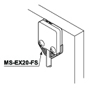
| Universal sensor mounting bracket | MS-EX20-FS | It is used when mounting the front sensing type from the rear side. (One set consists of 10 pcs.) | |||
Note 1 :
Note that the axis position of EX-23□ is different when replacing the mounting bracket MS-EX20-5 with MS-EXL2-4.
Round slit mask
OS-EX20-05
Fitted on the front face of the sensor with one-touch.
OS-EX20E-05
Fitted on the front face of the sensor with one-touch..
Rectangular slit mask
OS-EX20-05×3

Fitted on the front face of the sensor with one-touch.
OS-EX20E-05×3
Fitted on the front face of the sensor with one-touch.
Reflector
RF-210
Reflector mounting bracket
MS-RF21-1

Two M3 (length 12 mm0.472 in) screws with washers are attached.
Reflective tape
RF-11
RF-12
Sensor mounting bracket
MS-EX20-1

Material:Stainless steel (SUS304)Two M3 (length 5 mm0.197 in) pan head screws [stainless steel (SUS304)] are attached.
MS-EX20-2
Material:Stainless steel (SUS304)Two M3 (length 14 mm0.551 in) screws with washers [stainless steel (SUS304)] are attached.
MS-EX20-3

Material:Stainless steel (SUS304)Two M3 (length 5 mm0.197 in) pan head screws [stainless steel (SUS304)] are attached.
MS-EX20-4

Material:Stainless steel (SUS304)Two M3 (length 14 mm0.551 in) screws with washers [stainless steel (SUS304)] are attached.
Mounting spacer
MS-EX20-FS
Universal sensor mounting bracket
MS-EXL2-4
Two M3 (length 14 mm0.551 in) screws with washers, one M3 (length 10 mm0.394 in) hexagon-socket head bolt [stainless steel (SUS)], and one M3 hexagon nut [stainless steel (SUS)] are attached.
MS-EX20-5
Two M3 (length 12 mm0.472 in) screws with washers [stainless steel (SUS304)], one M3 (length 10 mm0.394 in) hexagon-socket head bolt [stainless steel (SUS304)], and one M3 hexagon nut [stainless steel (SUS304)] are attached.
Recommended e-CON connector
Manufactured by 3M Japan Limited
Adapted connector : 37104-4080-G00 FL
Please refer to "Introducing the 3M™ mini-clamp connector" for details.
------------------------------ Tab5 showing ------------------------------
Specifications
| Type | Thru-beam | Retroreflective | Diffuse reflective | ||
|---|---|---|---|---|---|
| Front sensing | Side sensing | Side sensing | Side sensing | ||
| Model No. (Note 2) | Light-ON | EX-21A (-PN) | EX-23 (-PN) (Note 3) | EX-29A (-PN) | EX-22A (-PN) |
| Dark-ON | EX-21B (-PN) | EX-29B (-PN) | EX-22B (-PN) | ||
| Applicable regulations and certifications | CE Marking (EMC Directive, RoHS Directive), UKCA Marking (EMC Regulations, RoHS Regulations), UL Recognition certification (Note 7) | ||||
| Sensing range | 1 m 3.281 ft | 2 m 6.562 ft | 30 to 200 mm 1.181 to 7.874 in (Note 4) | 5 to 160 mm 0.197 to 6.299 in (Note 5) with white non-glossy paper (200 x 200 mm) (7.874 x 7.874 in) | |
| Sensing object | Min. ø2.6 mm ø0.102 in opaque object (Setting distance between emitter and receiver: 1 m 3.281 ft) | Min. ø3 mm ø0.118 in opaque object (Setting distance between emitter and receiver: 2 m 6.562 ft) | ø15 mm ø0.591 in or more opaque or translucent object (Note 4, 6) | Opaque, translucent or transparent object (Note 6) | |
| Hysteresis | - | 15 % or less of operation distance [200 x 200 mm 7.874 x 7.874 in (with white non-glossy paper)] | |||
| Repeatability (perpendicular to sensing axis) | 0.05 mm 0.002 in or less | 0.5 mm 0.020 in or less | 0.3 mm 0.012 in or less | ||
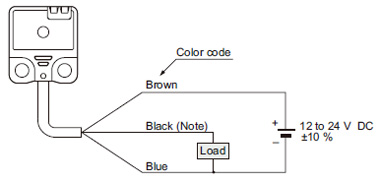
| Supply voltage | 12 to 24 V DC ± 10 % Ripple P-P 10 % or less | ||||
| Current consumption | Emitter: 10 mA or less, Receiver: 10 mA or less | 13 mA or less | |||
| Output | <NPN output type> NPN open-collector transistor ・Maximum sink current: 50 mA ・Applied voltage: 30 V DC or less (between output and 0 V) ・Residual voltage: 2 V or less (at 50 mA sink current) 1 V or less (at 16 mA sink current) <PNP output type> PNP open-collector transistor ・Maximum source current: 50 mA ・Applied voltage: 30 V DC or less (between output and +V) ・Residual voltage: 2 V or less (at 50 mA source current) 1 V or less (at 16 mA source current) | ||||
| Utilization category | DC-12 or DC-13 | ||||
| Short-circuit protection | Incorporated | ||||
| Response time | 0.5 ms or less | ||||
| Operation indicator | Orange LED (lights up when the output is ON) (thru-beam type: located on the receiver) | ||||
| Stability indicator | Green LED (lights up under stable light received condition or stable dark condition), located on the receiver | Green LED (lights up under stable light received condition or stable dark condition) | |||
| Sensitivity adjuster | - | Continuously variable adjuster, located on the emitter | Continuously variable adjuster | ||
| Operation mode switch | - | Located on the receiver | - | ||
| Pollution degree | 3 (Industrial environment) | ||||
| Protection | IP67 (IEC) | ||||
| Ambient temperature | -25 to +55 ℃ -13 to +131 ℉ (No dew condensation or icing allowed), Storage: -30 to +70 ℃ -22 to +158 ℉ | ||||
| Ambient humidity | 35 to 85 % RH, Storage: 35 to 85 % RH | ||||
| Ambient illuminance | Incandescent light: 3,000 lx or less at the light-receiving face | ||||
| Voltage withstandability | 1,000 V AC for one min. between all supply terminals connected together and enclosure | ||||
| Insulation resistance | 20 MΩ, or more, with 250 V DC megger between all supply terminals connected together and enclosure | ||||
| Vibration resistance | 10 to 500 Hz frequency, 3 mm 0.118 in double amplitude (20 G max.) in X, Y and Z directions for two hours each | ||||
| Shock resistance | 500 m/s2 acceleration (50 G approx.) in X, Y and Z directions three times each | ||||
| Emitting element | Red LED (modulated) | ||||
| Peak emission wavelength | 640 nm 0.025 mil | 650 nm 0.026 mil | 680 nm 0.027 mil | 680 nm 0.027 mil | |
| Material | Enclosure: Polyarylate, Lens: Polyarylate | ||||
| Cable | 0.1 mm2 3-core (thru-beam type sensor emitter: 2-core) cabtyre cable, 2 m 6.562 ft long | ||||
| Cable extension | Extension up to total 50 m 164.042 ft is possible with 0.3 mm2, or more, cable (thru-beam type: both emitter and receiver). | ||||
| Weight | Net weight (each emitter and receiver): 20 g approx. Gross weight: 60 g approx. | Net weight: 20 g approx., Gross weight: 45 g approx. | |||
| Accessories | - | Adjusting screwdriver: 1 pc. | RF-200 (Reflector): 1 pc. Adjusting screwdriver: 1 pc. | Adjusting screwdriver: 1 pc. | |
| Type | Convergent reflective | Narrow-view reflective | |||
|---|---|---|---|---|---|
| Diffused beam type | Small spot beam type | Long distance spot beam type | |||
| Front sensing | Side sensing | Side sensing | |||
| Model No. (Note 2) | Light-ON | EX-24A(-PN) | EX-26A(-PN) | EX-28A(-PN) | |
| Dark-ON | EX-24B(-PN) | EX-26B(-PN) | EX-28B(-PN) | ||
| Applicable regulations and certifications | CE Marking (EMC Directive, RoHS Directive), UKCA Marking (EMC Regulations, RoHS Regulations), UL Recognition certification (Note 7) | ||||
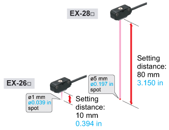
| Sensing range | 2 to 25 mm 0.079 to 0.984 in (Conv. point: 10 mm 0.394 in) with white non-glossy paper (50 x 50 mm) (1.969 x 1.969 in) | 6 to 14 mm 0.236 to 0.551 in (Conv. point: 10 mm 0.394 in) with white non-glossy paper (50 x 50 mm 1.969 x 1.969 in), spot diameter ø1 mm ø0.039 in with setting distance 10 mm 0.394 in | 45 to 115 mm 1.772 to 4.528 in with white non-glossy paper (100 x 100 mm 3.937 x 3.937 in), spot diameter ø5 mm ø0.197 in with setting distance 80 mm 3.150 in | ||
| Sensing object | Min. ø0.1 mm ø0.004 in copper wire (Setting distance: 10 mm 0.394 in) | Min. ø0.1 mm ø0.004 in copper wire (Setting distance: 10 mm 0.394 in) | Opaque, translucent or transparent object (Note 6) (Min. ø1 mm ø0.039 in copper wire at setting distance 80 mm 3.150 in) | ||
| Hysteresis | 15 % or less of operation distance [50 x 50 mm 1.969 x 1.969 in (EX-28□: 100 x 100 mm 3.937 x 3.937 in) (with white non-glossy paper)] | ||||
| Repeatability (perpendicular to sensing axis) | 0.1 mm 0.004 in or less (Setting distance: 10 mm 0.394 in) | 0.05 mm 0.002 in or less (Setting distance: 10 mm 0.394 in) | 0.3 mm 0.012 in or less | ||
| Supply voltage | 12 to 24 V DC ± 10 % Ripple P-P 10 % or less | ||||
| Current consumption | 13 mA or less | 15 mA or less | |||
| Output | <NPN output type> NPN open-collector transistor ・Maximum sink current: 50 mA ・Applied voltage: 30 V DC or less (between output and 0 V) ・Residual voltage: 2 V or less (at 50 mA sink current) 1 V or less (at 16 mA sink current) <PNP output type> PNP open-collector transistor ・Maximum source current: 50 mA ・Applied voltage: 30 V DC or less (between output and +V) ・Residual voltage: 2 V or less (at 50 mA source current) 1 V or less (at 16 mA source current) | ||||
| Utilization category | DC-12 or DC-13 | ||||
| Short-circuit protection | Incorporated | ||||
| Response time | 0.5 ms or less | ||||
| Operation indicator | Orange LED (lights up when the output is ON) | ||||
| Stability indicator | Green LED (lights up under stable light received condition or stable dark condition) | ||||
| Sensitivity adjuster | - | Continuously variable adjuster | |||
| Operation mode switch | - | ||||
| Pollution degree | 3 (Industrial environment) | ||||
| Protection | IP67 (IEC) | ||||
| Ambient temperature | -25 to +55 ℃ -13 to +131 ℉ (No dew condensation or icing allowed), Storage: -30 to +70 ℃ -22 to +158 ℉ | ||||
| Ambient humidity | 35 to 85 % RH, Storage: 35 to 85 % RH | ||||
| Ambient illuminance | Incandescent light: 3,000 lx or less at the light-receiving face | ||||
| Voltage withstandability | 1,000 V AC for one min. between all supply terminals connected together and enclosure | ||||
| Insulation resistance | 20 MΩ, or more, with 250 V DC megger between all supply terminals connected together and enclosure | ||||
| Vibration resistance | 10 to 500 Hz frequency, 3 mm 0.118 in double amplitude (20 G max.) in X, Y and Z directions for two hours each | ||||
| Shock resistance | 500 m/s2 acceleration (50 G approx.) in X, Y and Z directions three times each | ||||
| Emitting element | Red LED (modulated) | ||||
| Peak emission wavelength | 680 nm 0.027 mil | 650 nm 0.026 mil | 650 nm 0.026 mil | ||
| Material | Enclosure: Polyarylate, Lens: Polyarylate | ||||
| Cable | 0.1 mm2 3-core cabtyre cable, 2 m 6.562 ft long | ||||
| Cable extension | Extension up to total 50 m 164.042 ft is possible with 0.3 mm2, or more, cable. | ||||
| Weight | Net weight: 20 g approx., Gross weight: 45 g approx. | ||||
| Accessories | - | Adjusting screwdriver: 1 pc. | |||
Notes:
1) Where measurement conditions have not been specified precisely, the conditions used were an ambient temperature of +23 ℃ +73.4 ℉.
2) Model Nos. having the suffix "-PN" are PNP output type.
3) Either Light-ON or Dark-ON can be selected by the operation mode switch (located on the receiver).
4) The sensing range and the sensing object of the retroreflective type sensor are specified for the RF-200 reflector. Further, the sensing range is the possible setting range for the reflector. The sensor can detect an object less than 30 mm 1.181 in away. However, if the reflector is set 100 mm 3.937 in or less away, the sensing object should be opaque.
5) In case of using this product at a sensing range of 50 mm 1.969 in or less, take care that the sensitivity adjustment range becomes extremely narrow.
6) Make sure to confirm detection with an actual sensor before use.
7) Excluding 5 m cable length type.
------------------------------ Tab6 showing ------------------------------
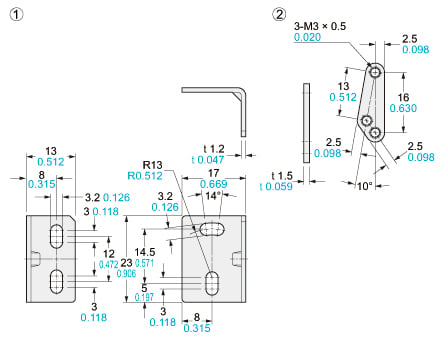
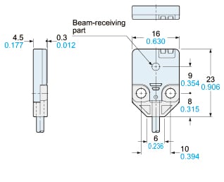
Dimensions
- Unit: mm in
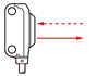
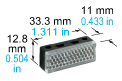
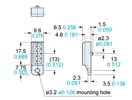
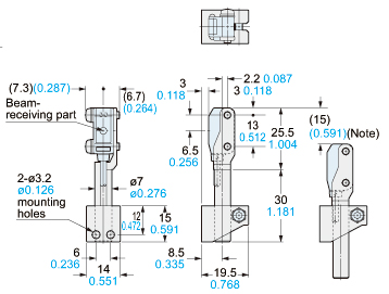
EX-21□
Sensor
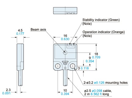
Note:Not incorporated on the emitter.
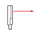
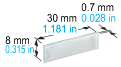
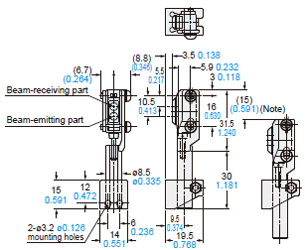
EX-23□
Sensor
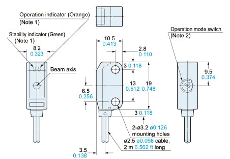
Notes:1) Not incorporated on the emitter.2) It is the sensitivity adjuster on the emitter.
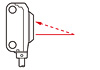
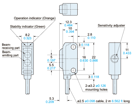
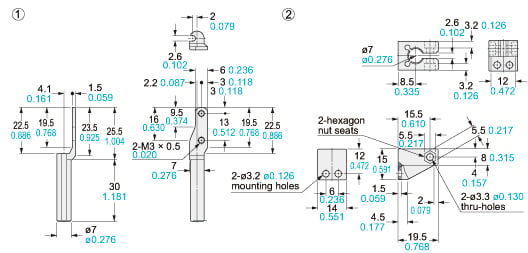
EX-29□ EX-22□
EX-26□ EX-28□
Sensor
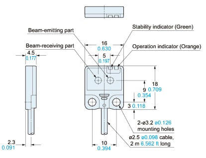
EX-24□
Sensor
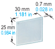
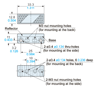
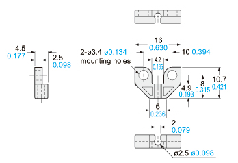
RF-200
Reflector (Accessory for the retroreflective type sensor)
Material:Acrylic (Reflector)ABS (Base)
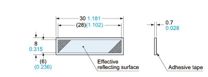
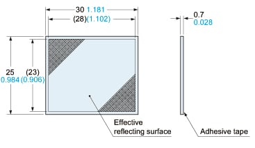
RF-210
Reflector (Optional)
Material:Acrylic (Reflector) ABS (Base)Two M3 (length 8 mm0.315 in) screws with washers and two nuts are attached.
RF-11
Reflective tape (Optional)
Material:Flexible Polyvinyl Chloride
RF-12
Reflective tape (Optional)
Material:Flexible Polyvinyl Chloride
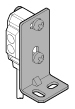
MS-RF21-1
Reflector mounting bracket for RF-210 (Optional)
Material:Stainless steel (SUS304)Two M3 (length 12 mm0.472 in) screws with washers are attached.
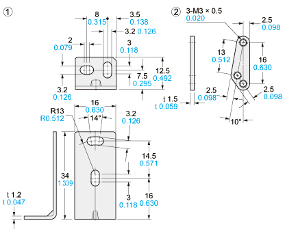
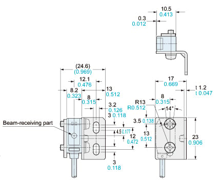
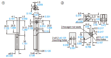
Assembly dimensions
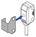
MS-EX20-1
Sensor mounting bracket (Optional)
Material: Stainless steel (SUS304) Two M3 (length 5 mm 0.197 in) pan head screws [stainless steel (SUS304)] are attached.
Assembly dimensions
Mounting drawing with EX-21□
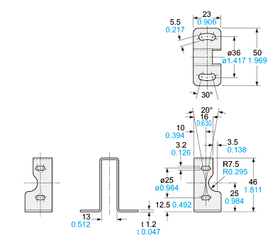
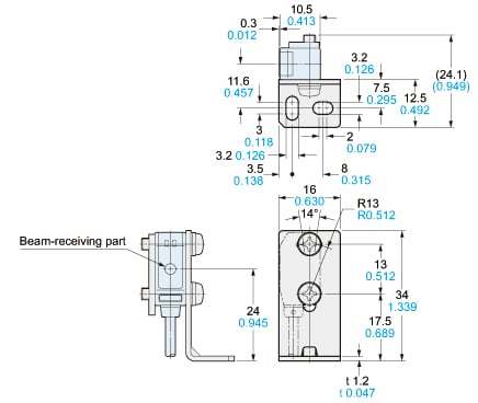
MS-EX20-2
Sensor mounting bracket (Optional)
Material:Stainless steel (SUS304)Two M3 (length 14 mm0.551 in) screws with washers [stainless steel (SUS304)] are attached.
Assembly dimensions
Mounting drawing with the receiver of EX-23□
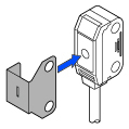
MS-EX20-3
Sensor mounting bracket (Optional)
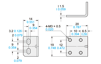
Material:Stainless steel (SUS304)Two M3 (length 5 mm0.197 in) pan head screws [stainless steel (SUS304)] are attached.
Assembly dimensions
Mounting drawing with the receiver of EX-21□
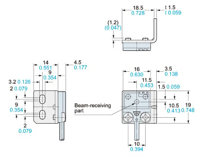
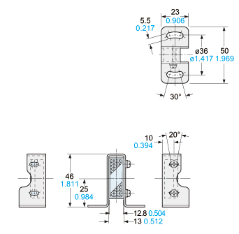
MS-EX20-4
Sensor mounting bracket (Optional)
Material:Stainless steel (SUS304)Two M3 (length 14 mm0.551 in) screws with washers [stainless steel (SUS304)] are attached.
Assembly dimensions
Mounting drawing with the receiver of EX-23□
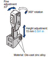
MS-EXL2-4
Universal sensor mounting bracket (Optional)
Material:Die-cast zinc alloyTwo M3 (length 14 mm0.551 in) screws with washers, one M3 (length 10 mm0.394 in) hexagon socket-head bolt [stainless steel (SUS)], and one M3 hexagon nut [stainless steel (SUS)] are attached.
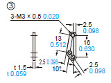
Material: Stainless steel (SUS)
Note: This is the adjustable range of the movable part.
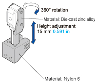
MS-EX20-5
Universal sensor mounting bracket (Optional)
Material:Die-cast zinc alloyTwo M3 (length 12 mm0.472 in) screws with washers [stainless steel (SUS304)], one M3 (length 10 mm0.394 in) hexagon socket-head bolt [stainless steel (SUS304)], and one M3 hexagon nut [stainless steel (SUS304)] are attached.
Assembly dimensions
Mounting drawing with the receiver of EX-23□
Note: This is the adjustable range of the movable part.
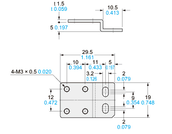
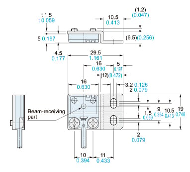
MS-EX20-FS
Mounting spacer (Optional)
Material:Polycarbonate
Assembly dimensions
Mounting drawing with the receiver of EX-21□
------------------------------ Tab7 showing ------------------------------
I/O Circuit and Wiring diagrams
NPN output type
I/O circuit diagram
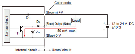
Note:The emitter of the thru-beam type sensor does not incorporate the output.
Symbols・・・
D1: Reverse supply polarity protection diode
D2: Reverse output polarity protection diode
ZD : Surge absorption zener diode
Tr : NPN output transistor
Wiring diagram
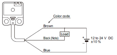
Note:The emitter of the thru-beam type sensor does not incorporate the black wire.
PNP output type
I/O circuit diagram
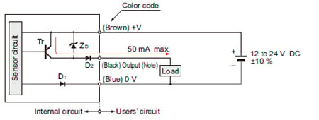
Note:The emitter of the thru-beam type sensor does not incorporate the output.
Symbols・・・
D1: Reverse supply polarity protection diode
D2: Reverse output polarity protection diode
ZD : Surge absorption zener diode
Tr : PNP output transistor
Wiring diagram
Note:The emitter of the thru-beam type sensor does not incorporate the black wire.
------------------------------ Tab8 showing ------------------------------
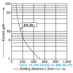
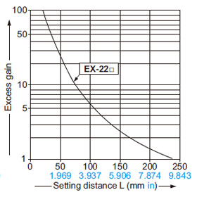
Sensing characteristics
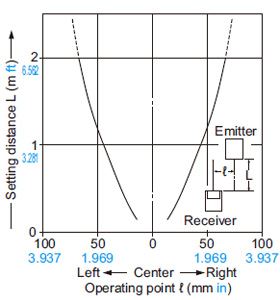
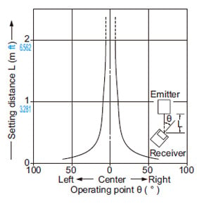
EX-21□ EX-23□ EX-29□ EX-22□
Correlation between setting distance and excess gain
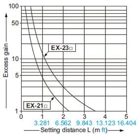
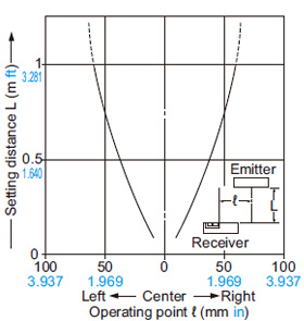
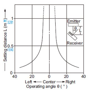
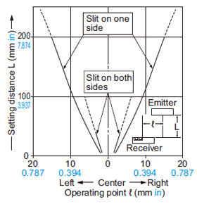
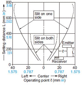
EX-21□
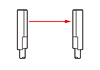
Thru-beam type
Parallel deviation
Angular deviation
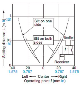
Parallel deviation with round slit masks
(ø0.5 mm ø0.020 in)
Parallel deviation with rectangular slit masks
(0.5 × 3 mm 0.020 × 0.118 in)
EX-23□
Thru-beam type
Parallel deviation
Angular deviation
Parallel deviation with round slit masks
(ø0.5 mm ø0.020 in)
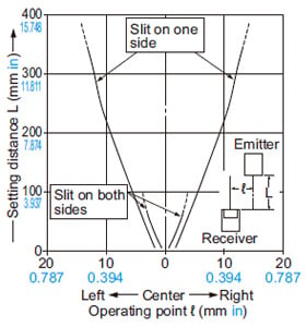
Parallel deviation with rectangular slit masks
(0.5 × 3 mm 0.020 × 0.118 in)
Parallel deviation with rectangular slit
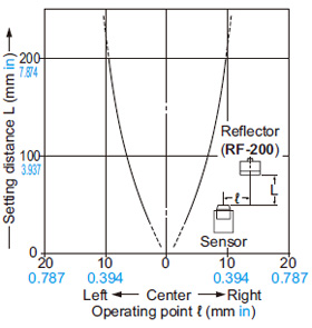
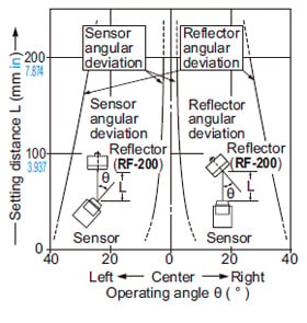
EX-29□
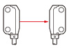
Retroreflective type
Parallel deviation
Angular deviation
EX-22□
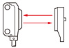
Diffuse reflective type
Sensing field
Correlation between sensing object size and sensing range
As the sensing object size becomes smaller than the standard size (white non-glossy paper 200 × 200 mm 7.874 × 7.874 in), the sensing range shortens, as shown in the left graph.
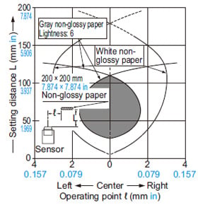
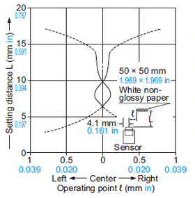
EX-24□
Convergent reflective type
Sensing fields
• Horizontal (left and right) direction
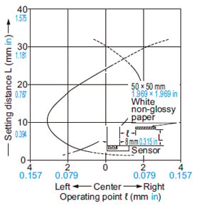
• Vertical (up and down) direction
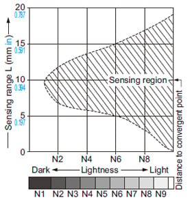
Correlation between lightness and sensing range
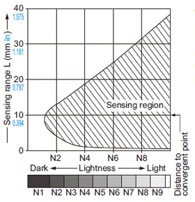
The sensing region (typical) is represented by oblique lines in the left figure. However, the sensitivity should be set with enough margin because of slight variation in products.
(Lightness shown on the left may differ slightly from the actual object condition.)
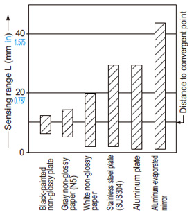
Correlation between material (50 × 50 mm 1.969 × 1.969 in) and sensing range
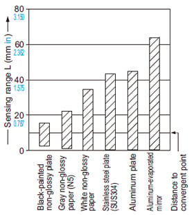
The bars in the graph indicate the sensing range (typical) for the respective material.
However, there is a slight variation in the sensing range depending on the product.
Further, if there is a reflective object (conveyor, etc.) in the background of the sensing object, since it affects the sensing, separate it by more than twice the sensing range shown in the left graph.
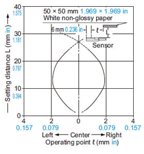
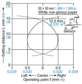
EX-26□
Convergent reflective type
Sensing fields
• Horizontal (left and right) direction
• Vertical (up and down) direction
Correlation between lightness and sensing range
The sensing region (typical) is represented by oblique lines in the left figure. However, the sensitivity should be set with enough margin because of slight variation in products.
(The graph is drawn for the maximum sensitivity setting.)
(Lightness shown on the left may differ slightly from the actual object condition.)
Correlation between material (50 × 50 mm 1.969 × 1.969 in) and sensing range
The bars in the graph indicate the sensing range (typical) for the respective material. However, there is a slight variation in the sensing range depending on the productFurther, if there is a reflective object (conveyor, etc.) in the background of the sensing object, since it affects the sensing, separate it by more than twice the sensing range shown in the left graph, or adjust the sensitivity adjuster.
(The graph is drawn for the maximum sensitivity setting.)
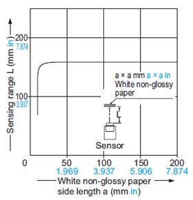
EX-28□
Narrow-view reflective type
Sensing field
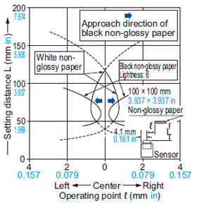
Correlation between sensing object size and sensing range
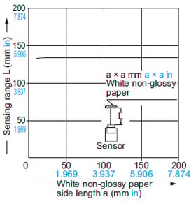
As the sensing object size becomes smaller than the standard size (white non-glossy paper 100 × 100 mm 3.937 × 3.937 in), the sensing range shortens, as shown in the left graph.
------------------------------ Tab9 showing ------------------------------
Mounting
- Mount using M3 screws. The tightening torque should be 0.5 N·m or less.
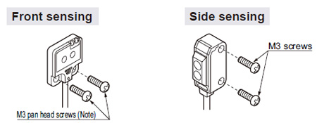
Note:When mounting the front sensing type sensor, use M3 pan head screws without washers, etc.
Mounting method
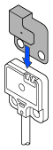
- When mounting the front sensing type from the backside, fit the mounting spacer (MS-EX20-FS) and fix with screws.
1 Fit the mounting spacer on the sensor.
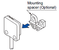
2 Align the mounting holes of the mounting spacer and the sensor and mount with M3 screws. The tightening torque should be 0.5 N·m or less.
Sensitivity adjustment (side sensing type only)
| Step | Sensitivity adjuster | Description |
|---|---|---|
| 1 |  | Turn the sensitivity adjuster fully counterclockwise to the minimum sensitivity position (• mark). |
| 2 | 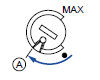 | In the light received condition, turn the sensitivity adjuster slowly clockwise and confirm the point Ⓐ where the sensor enters the “Light” state operation. |
| 3 | 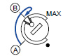 | In the dark condition, turn the sensitivity adjuster further clockwise until the sensor enters the “Light” state operation and then bring it back to confirm point Ⓑ where the sensor just returns to the “Dark” state operation. (If the sensor does not enter the “Light” state operation even when the sensitivity adjuster is turned fully clockwise, this extreme position is point Ⓑ .) |
| 4 | 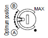 | The position at the middle of points Ⓐ and Ⓑ is the optimum sensing position. |
Notes:
1)Use the attached adjusting screwdriver to turn the adjuster slowly.
Turning with excessive strength will damage the adjuster.
2)In case of using EX-22□ at a sensing distance of 50 mm 1.969 in or less, take care that the sensitivity adjustment range becomes extremely narrow.
Operation mode switch (EX-23□ only)
| Switch position | Description |
|---|---|
 | Light-ON mode is obtained when the operation mode switch (located on the receiver) is turned fully clockwise (L side). |
 | Dark-ON mode is obtained when the operation mode switch (located on the receiver) is turned fully counterclockwise (D side). |
Note:Operation mode switch should be turned fully till it stops.
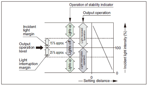
Stability indicator
- The stability indicator (green) lights up when the incident light intensity has sufficient margin with respect to the operation level.
If the incident light intensity level is such that the stability indicator lights up, stable sensing can be done without the light received operation and the light interrupted operation being affected by a change in ambient temperature or supply voltage.
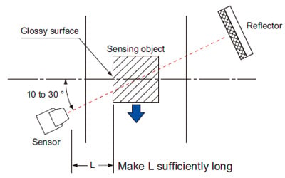
Glossy object sensing (EX-29□)
- Please take care of the following points when detecting materials having a gloss.
Wiring
- Excess bending of the cable or stress applied to the cable may disconnect the internal lead wire.
Others
- This product has been developed / produced for industrial use only.
- This product is suitable for indoor use only.
- Do not use during the initial transient time (50 ms) after the power supply is switched on.
- If sensors are mounted close together and the ambient temperature is near the maximum rated value, provide for enough heat radiation / ventilation.
- If a reflective object is present in the background, the sensing of EX-28□ may be affected. When setting the sensor, make sure to confirm that the reflective object has no effect. In case the reflective object affects the sensing, take measures such as removing the reflective object or coloring it in black, etc.