Discontinued Products
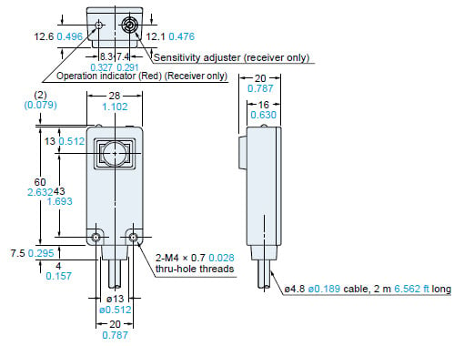
Dimensions
- Unit: mm in
US-N300
Sensor
MS-N30
Sensor mounting bracket (Accessory)
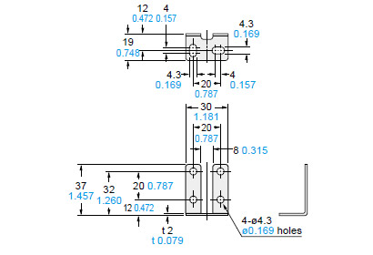
Material: Cold rolled carbon steel (SPCC)Two M4 (length 15 mm0.591 in) screws with washers are attached.
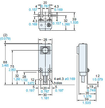
Assembly dimensions
Mounting drawing with the receiver
I/O Circuit and Wiring diagrams
I/O circuit diagram
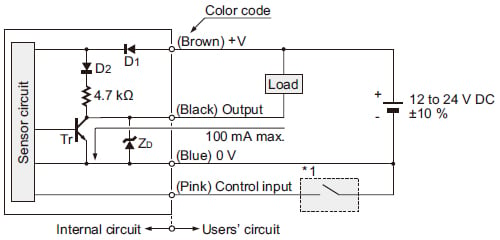
Note: The transmitter has only two power supply wires (V and 0 V).
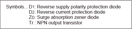
Wiring diagram
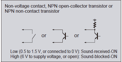
*1
Sensing characteristics
Parallel deviation
Angular deviation
Sensing field
Mounting
- The tightening torque should be 0.49 N·m or less.
Sensitivity adjustment
- Normally, use the sensor at the maximum sensitivity.
However, if the sensing is not proper due to surrounding objects (reflection from surrounding objects, etc.), adjust the sensitivity.
Influence of surrounding objects
Influence of an object parallel to the sensing axis
<Countermeasure>
- If there is a wall or a curtain near the sensing axis, the sound reflection may cause the operation to be unstable.
Influence of background objects
- If sensor heads are installed as shown in the figure below, the operation may become unstable by the reflected sound wave.
<Countermeasure>
- The receiver should be placed away from the object and at an angle to it as shown below.

Mutual interference
<Countermeasure>
- When two or more sensors are mounted close together, the sensors may not enter the “sound-blocked state” due to mutual interference.
Traveling speed and minimum sensing object width
- Minimum sensing object width is 20 × 20 mm 0.787 × 0.787 in in the stationary condition. The minimum sensing width of a traveling object is related to the traveling speed and the sensor response time by the following formula.
W=VT+A(m)
W:Minimum sensing object width(m)
V:Traveling speed of the object (m/sec.)
T:Sensor response time = 0.005 (sec.)
A:Minimum sensing object width in the stationary condition = 0.02 0.066 (m ft)
(Example) V=10m 32.808 ft /sec.
W=10 32.808 × 0.005 0.016 + 0.02 0.066
=0.07 m 0.230 ft
=70 mm 2.756 in
Others
- Do not use during the initial transient time (50 ms) after the power supply is switched on.
- The ultrasonic sound propagates through the air. If the sensor is used at a place where air blows or the temperature suddenly changes (near a door, an air conditioner, etc.) the operation may become unstable. Avoid using US-N300 at such places.
- Take care that the sensor may malfunction due to an intense extraneous sound, such as, metal impact sound.
- Do not expose the transmitting element or the receiving element to moisture or dust. It may affect the sensing operation.