Discontinued Products
Dimensions
- Unit: mm in
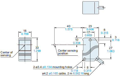
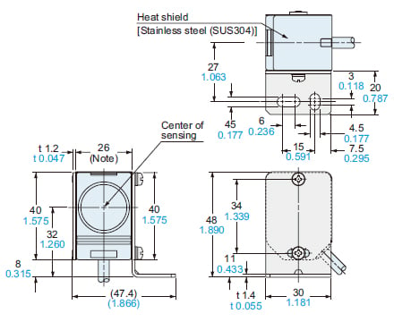
TH-11CS
Spot type
Sensor head / TH-11
Controller / TH-C1
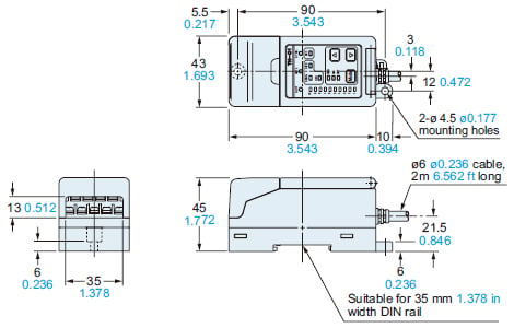
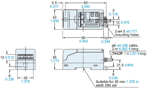
TH-12CS
TH-12CPS
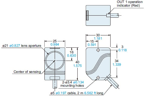
Long sensing range type
Sensor head / TH-12
Controller / TH-C2, TH-C2P
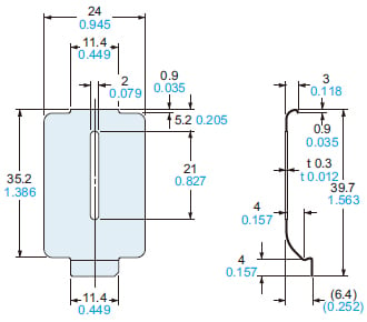
MS-TH-1
Sensor head mounting bracket for spot type (Accessory for TH-11)
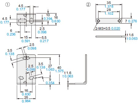
Material:Cold rolled carbon steel (SPCC)Two M3 (length 25 mm0.984 in) screws with washers are attached.
Assembly dimensions
The drawing below shows MS-TH-1 mounted on TH-11 fitted with heat shield TH-B1 (accessory).
Note:18 mm0.709 inwhen the heat shield is not used.
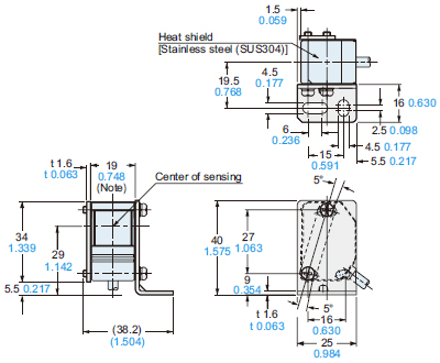
MS-TH-2
Sensor head mounting bracket for long sensing range type (Accessory for TH-12)
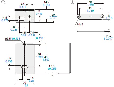
Material: Cold rolled carbon steel (SPCC)Two M3 (length 30 mm1.181 in) screws with washers are attached.
Assembly dimensions
The drawing below shows MS-TH-2 mounted on TH-12 fitted with heat shield TH-B2 (accessory)
Note:25 mm0.984 inwhen the heat shield is not used.
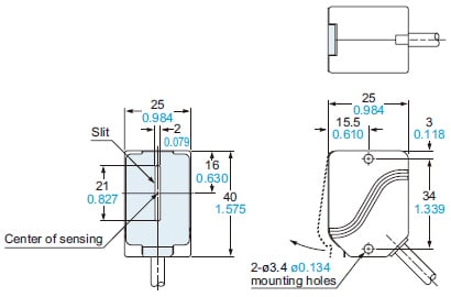
OS-TH12
Slit mask for long sensing range type (Accessory for TH-12)
Material: Stainless steel (SUS304)
Assembly dimensions
I/O Circuit and Wiring diagrams
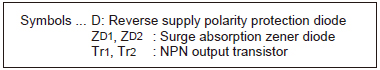
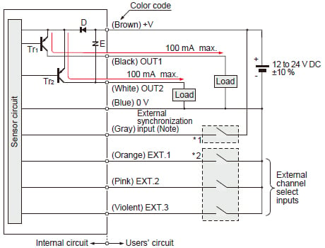
NPN output type
I/O circuit diagram
Controller / TH-C1, TH-C2
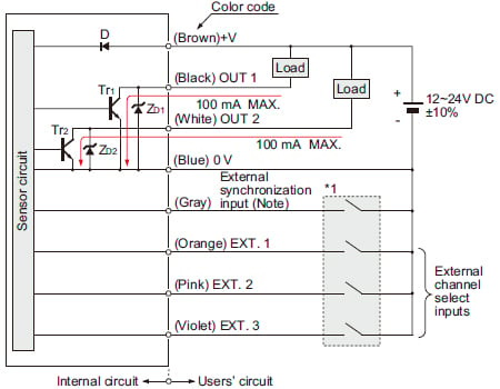
Note: The external synchronization input is active Low.
*1

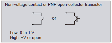
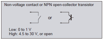
Specifying channel with external channel select inputs
| Channel No. | EXT.1 (Orange) | EXT.2 (Pink) | EXT.3 (Violet) |
|---|---|---|---|
| 1 | L | H | H |
| 2 | H | L | H |
| 3 | L | L | H |
| 4 | H | H | L |
| 5 | L | H | L |
| 6 | H | L | L |
| 7 | L | L | L |
| 8 | H | H | H |
L: Low (0 to 1 V), H: High (4.5 to 30 V, or open)
Notes:
1)The channel can be specified from the front panel only when all external channel select inputs (EXT.1, EXT.2, and EXT.3) are High (corresponding to Channel No. 8).
2)The external channel select inputs take precedence over the front panel channel selection (except for Channel No. 8).
3)If channel specification is changed from front panel operation to external channel select inputs and Channel No. 8 is to be selected by the external channel call inputs, make sure to specify a channel other than No. 8 before setting all the external channel select inputs (EXT.1, EXT.2, EXT.3) to High.
If this operation is not done, channel specification by front panel operation gets precedence.
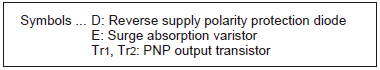
PNP output type
I/O circuit diagram
Controller / TH-C2P
Note: The external synchronization input is active High.
*1
*2
Specifying channel with external channel select inputs
| Channel No. | EXT.1 (Orange) | EXT.2 (Pink) | EXT.3 (Violet) |
|---|---|---|---|
| 1 | L | H | H |
| 2 | H | L | H |
| 3 | L | L | H |
| 4 | H | H | L |
| 5 | L | H | L |
| 6 | H | L | L |
| 7 | L | L | L |
| 8 | H | H | H |
L: Low (0 to 1 V), H: High (4.5 to 30 V, or open)
Notes:
1)The channel can be specified from the front panel only when all external channel select inputs (EXT.1, EXT.2, and EXT.3) are High (corresponding to Channel No. 8).
2)The external channel select inputs take precedence over the front panel channel selection (except for Channel No. 8).
3)If channel specification is changed from front panel operation to external channel select inputs and Channel No. 8 is to be selected by the external channel call inputs, make sure to specify a channel other than No. 8 before setting all the external channel select inputs (EXT.1, EXT.2, EXT.3) to High.
If this operation is not done, channel specification by front panel operation gets precedence.