Basic Information
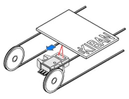
Convergent reflection sensing ensures stable detection


Features
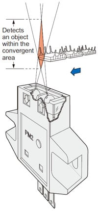
Stable detection by convergent reflective mode
Stable detection characteristics are obtained since it is convergent reflective type and senses a limited area.
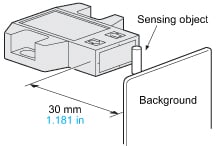
Hardly affected by background
Even a specular background does not affect the sensing performance if the sensor is located 30 mm 1.181 in away from it.
(However, the specular background should be a plane surface, directly facing the sensor. A spherical or curved background may be detected.)
Dark object detectable
Since the sensor is very sensitive, it can detect even a dark object of low reflectivity.
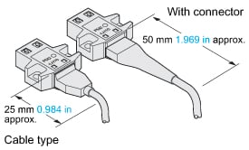
Cable type is also available
Cumbersome soldering is not required.
It saves space and improves reliability.
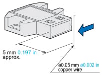
Minute object detectable
A ø0.05 mm ø0.002 in copper wire can be detected at a distance of 5 mm 0.197 in under the optimum condition.
Applications
Sensing capacitors in a tray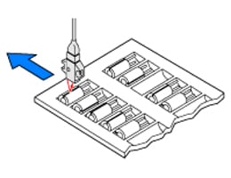
Order guide
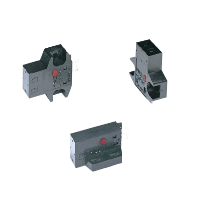
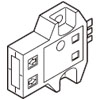
Connector type
| Type | Appearance | Sensing range | Model No. | Output | Output operation |
|---|---|---|---|---|---|
| Top sensing |
| 2.5 to 8 mm 0.098 to 0.315 in (Convergent point: 5 mm 0.197 in) | PM2-LH10 | NPN open-collector transistor | Light-ON |
| PM2-LH10B | Dark-ON | ||||
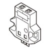
| Front sensing |
| PM2-LF10 | Light-ON | ||
| PM2-LF10B | Dark-ON | ||||
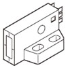
| L type (Top sensing) |
| PM2-LL10 | Light-ON | ||
| PM2-LL10B | Dark-ON |
Cable type
| Type | Appearance | Sensing range | Model No. | Output | Output operation |
|---|---|---|---|---|---|
| Top sensing |
| 2.5 to 8 mm 0.098 to 0.315 in (Convergent point: 5 mm 0.197 in) | PM2-LH10-C1 | NPN open-collector transistor | Light-ON |
| PM2-LH10B-C1 | Dark-ON | ||||
| Front sensing |
| PM2-LF10-C1 | Light-ON | ||
| PM2-LF10B-C1 | Dark-ON | ||||
| L type (Top sensing) |
| PM2-LL10-C1 | Light-ON | ||
| PM2-LL10B-C1 | Dark-ON |

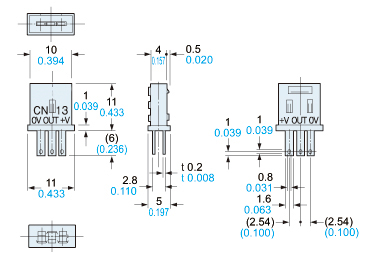
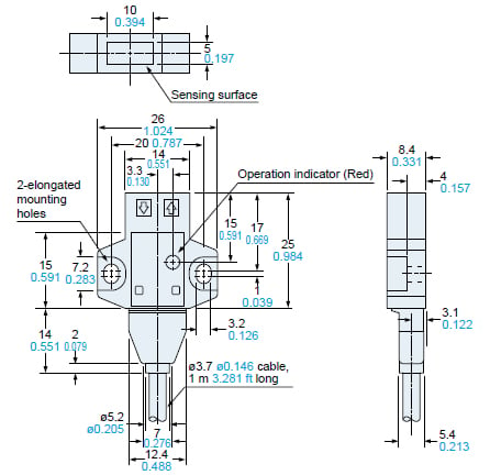
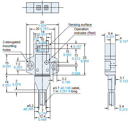
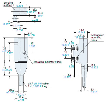
Dimensions
- Unit: mm in
PM2-LH10
PM2-LH10B
Sensor
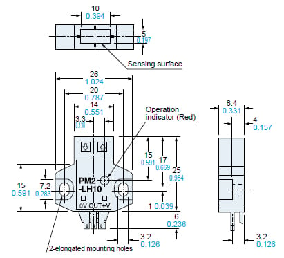
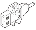
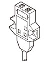
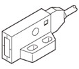
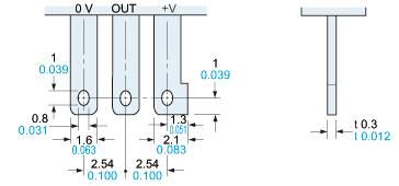
* Terminal part (Connector type)

PM2-LF10
PM2-LF10B
Sensor
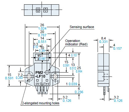
* Terminal part (Connector type)

PM2-LL10
PM2-LL10B
Sensor
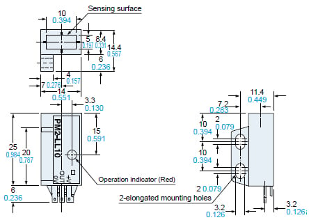
* Terminal part (Connector type)
CN-13
Connector (Optional)
PM2-LH10-C1
PM2-LH10B-C1
Sensor
PM2-LF10-C1
PM2-LF10B-C1
Sensor
PM2-LL10-C1
PM2-LL10B-C1
Sensor
I/O Circuit and Wiring diagrams
I/O circuit diagram
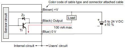
Note:Make sure to connect terminals correctly as the sensor does not incorporate a reverse polarity protection circuit.
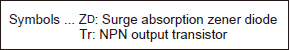
Wiring diagram
Note:Make sure to connect terminals correctly as the sensor does not incorporate a reverse polarity protection circuit.
Sensing characteristics
(TYPICAL)
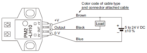
Sensing fields
•Horizontal (left and right) direction
The sensors can be mounted side by side.However, if the sensor is slanted, there may be interference. Verify first whether there is any interference prior to use.
•Vertical (up and down) direction
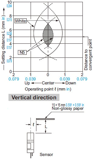
The sensors can be mounted side by side.However, if the sensor is slanted, there may be interference. Verify first whether there is any interference prior to use.
Correlation between lightness and sensing range
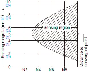
The sensing region (typical) is represented by oblique lines in the left figure.
However, the sensitivity should be set with enough margin because of slight variation in products.
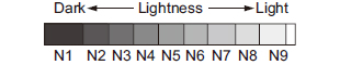
(Lightness shown on the left may differ slightly from the actual object condition.)
Correlation between material (15 × 15 mm 0.591 × 0.591 in) and sensing range
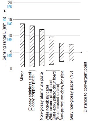
The bars in the graph indicate the sensing range (typical) for the respective material. However, there is a slight variation in the sensing range depending on the product.
Further, if there is a reflective object (conveyer, etc.) in the background of the sensing object, since it affects the sensing, separate it by more than twice the sensing range shown in the left graph.
Mounting
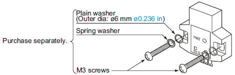
- When fixing the sensor with screws, use M3 screws and the tightening torque should be 0.49 N·m or less.
Further, use small, round type plain washers (ø6 mm ø0.236 in).
Others
- This product has been developed / produced for industrial use only.
- This product is suitable for indoor use only.
- Do not use during the initial transient time (50 ms) after the power supply is switched on.
- Take care that the product does not come in direct contact with oil, grease, or organic solvents, such as, thinner, etc.
Wiring
- Make sure to connect terminals correctly as the sensor does not incorporate a reverse polarity protection circuit.
- If the sensor is being used in a noisy environment, examine the extent of noise. Further, if equipment, such as motor, solenoid or electromagnetic valve, which generates a large surge, is present near the sensor, connect a surge absorber to the equipment.
Setting
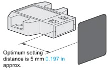
- The optimum setting distance (distance to convergent point) is 5 mm 0.197 in.
The sensor is not affected even by a specular background if it is located 30 mm 1.181 in, or more, away from the sensor.
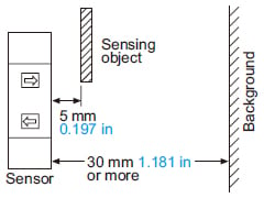
(However, the specular background should be a plane surface, directly facing the sensor. A spherical or curved background may be detected.)
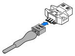
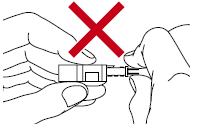
Procedures of plugging or unplugging a connector
(1) Insert a connector straight into a sensor until the connector lug is locked by the sensor hook.
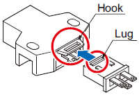
(2) When unplugging, give as much stress as a connector lug can be relieved from a hook. Then unplug it.
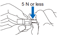
Caution:
Be sure to hold a connector when plugging or unplugging it. Do not hold a terminal or a cable when plugging or unplugging the connector. Otherwise, it will cause a poor contact.
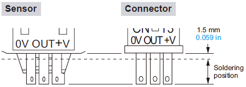
Soldering (Both connector CN-13 and sensor)
| Soldering temperature | 260 ℃ 500 ℉ or less |
|---|---|
| Soldering time | 10 sec. or less |
| Soldering position | Refer to the below figure |
- If soldering is done directly on the terminals, strictly adhere to the conditions given below.
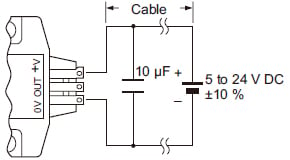
Wiring
- The cable length must be 2 m 6.562 ft, or less, with 0.3 mm2, or more, cable. If the cable is extended for more than 2 m 6.562 ft, connect a capacitor of 10 μF approx. between +V and 0 V terminals.