Discontinued Products
Specifications
| Type | Ultra-small | ||
|---|---|---|---|
| With flexible cable | |||
| Model No. | NPN output | PM-□24 | PM-□24-R |
| PNP output | PM-□24P | - | |
| Sensing range | 5 mm 0.197 in (fixed) | ||
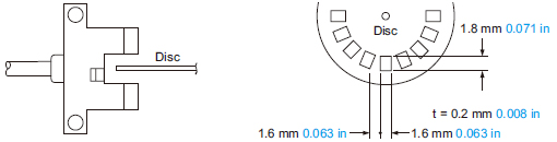
| Minimum sensing object | 0.8 x 1.8 mm 0.031 x 0.071 in opaque object | ||
| Hysteresis | 0.05 mm 0.002 in or less | ||
| Repeatability | 0.03 mm 0.001 in or less | ||
| Supply voltage | 5 to 24 V DC ±10 % Ripple P-P 10 % or less | ||
| Current consumption | 15 mA or less | ||
| Output | <NPN output type> NPN open-collector transistor • Maximum sink current: 50 mA • Applied voltage: 30 V DC or less (between output and 0 V) • Residual voltage: 0.7 V or less (at 50 mA sink current), 0.4 V or less (at 16 mA sink current) <PNP output type> PNP open-collector transistor • Maximum source current: 50 mA • Applied voltage: 30 V DC or less (between output and + V) • Residual voltage: 0.7 V or less (at 50 mA source current), 0.4 V or less (at 16 mA source current) | ||
| Utilization category | DC-12 or DC-13 | ||
| Output operation | Incorporated with 2 outputs: Light-ON / Dark-ON | ||
| Response time | Under light received condition: 20 µs or less Under light interrupted condition: 100 µs or less (Response frequency: 1 kHz or more) (Note 2) | ||
| Operation indicator | Vermilion LED (lights up under light received condition) | ||
| Pollution degree | 3 (Industrial environment) | ||
| Ambient temperature (Note 3, 4) | –25 to +55 ℃ –13 to +131 ℉ (No dew condensation or icing allowed), Storage: –30 to +80 ℃ –22 to +176 ℉ | ||
| Ambient humidity | 35 to 85 % RH, Storage: 35 to 85 % RH | ||
| Ambient illuminance | Fluorescent light: 1,000 ℓx at the light-receiving face | ||
| EMC | EN 60947-5-2 | ||
| Voltage withstandability | 1,000 V AC for one min. between all supply terminals connected together and enclosure | ||
| Insulation resistance | 50 MΩ, or more, with 250 V DC megger between all supply terminals connected together and enclosure | ||
| Vibration resistance | 10 to 2,000 Hz frequency, 1.5 mm 0.059 in amplitude in X, Y and Z directions for two hours each | ||
| Shock resistance | 15,000 m/s2 acceleration (1,500 G approx.) in X, Y and Z directions for three times each | ||
| Emitting element | Infrared LED (Peak emission wavelength: 940 nm 0.037 mil, non-modulated) | ||
| Material | Enclosure: PBT, Slit cover: Polycarbonate | ||
| Cable | 0.09 mm2 4-core cabtyre cable [PM-□24-R: 0.1 mm2 flexible, oil and heat resistant cabtyre cable (Note 5)], 1 m 3.281 ft long | ||
| Cable extension | Extension up to total 100 m 328.084 ft is possible with 0.3 mm2, or more, cable. | ||
| Weight | Net weight: 10 g approx. | ||
Notes:
1) Where measurement conditions have not been specified precisely, the conditions used were an ambient temperature of +23 ℃ +73.4 ℉.
2) The response frequency is the value when the disc, given in the figure below, is rotated.
3) In case the PM-24 series is used at an ambient temperature of +50 ℃ +122 ℉, or more, make sure to mount it on a metal body.
4) Take care that the flexibility of the PM-□24-R cable is lost if the ambient temperature in –10 ℃ +14 ℉ or less.
5) The cable of PM-□24-R is a flexible cable usable on a moving base. When the sensor is mounted on a moving base, fix the sensor cable joint so that stress is not applied to it. (Models other than the PM-□24-R cannot be used on a moving base.)
Dimensions
- Unit: mm in
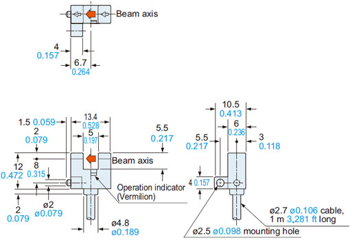
PM-K24(P)
PM-K24-R
Sensor
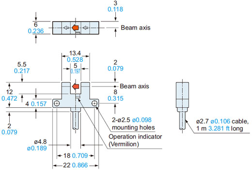
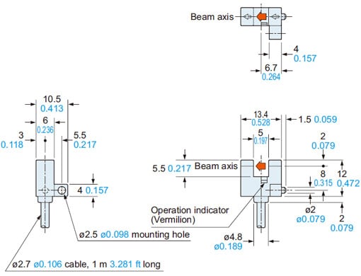
PM-L24(P)
PM-L24-R
Sensor
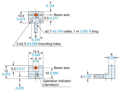
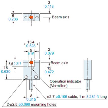
PM-F24(P)
PM-F24-R
Sensor
PM-R24(P)
PM-R24-R
Sensor
PM-U24(P)
PM-U24-R
Sensor
I/O Circuit and Wiring diagrams
PM-□24
PM-□24-R
NPN output type
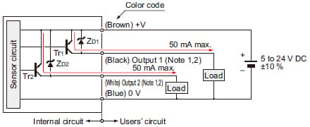
I/O circuit diagram
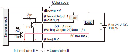
Notes:1)Make sure to connect terminals correctly as the sensor does not incorporate a reverse polarity protection circuit.Further, the output is not incorporated with a short-circuit protection circuit. Do not connect it directly to a power supply or a capacitive load. Faulty wiring may result in damage.2)Ensure to insulate the unused output wire.
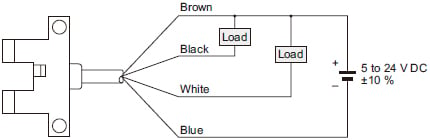
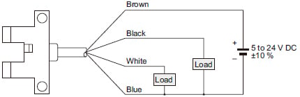
Wiring diagram
Output operation
| Color code | Output operation | |
|---|---|---|
| Output 1 | Black | Light-ON |
| Output 2 | White | Dark-ON |
PM-□24P
PNP output type
I/O circuit diagram
Notes:1)Make sure to connect terminals correctly as the sensor does not incorporate a reverse polarity protection circuit.Further, the output is not incorporated with a short-circuit protection circuit. Do not connect it directly to a power supply or a capacitive load. Faulty wiring may result in damage.2)Ensure to insulate the unused output wire.
Wiring diagram
Output operation
| Color code | Output operation | |
|---|---|---|
| Output 1 | Black | Light-ON |
| Output 2 | White | Dark-ON |
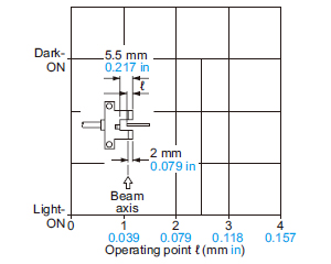
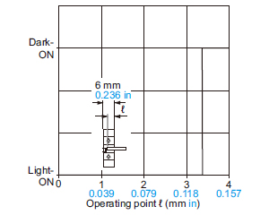
Sensing characteristics
(TYPICAL)
Sensing position
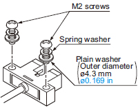
Mounting
- When fixing the sensor with screws, use M2 screws and the tightening torque should be 0.15 N·m or less.
Further, use small, round type plain washers. (ø4.3 mm ø0.169 in)
When using the optional mounting screw set MS-M2, a spring washer is included.
- In case the PM-24 series is used at an ambient temperature of +50 ℃ +122 ℉, or more, make sure to mount it on a metal body.
Cable extension
- Cable extension is possible up to an overall length of 100 m 328.084 ft with a 0.3 mm2, or more, cable.
However, since a voltage drop shall occur due to the cable extension, ensure that the power supply voltage at the end of the cable attached to the sensor is within the rating.
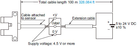
But, when the overall cable length, including the cable attached to the sensor, is as given below, there is no need to confirm the voltage.
| Conductor cross section area of extension cable | Total cable length |
|---|---|
| 0.08 to 0.1 mm2 | Up to 5 m 16.404 ft |
| 0.2 mm2 | Up to 10 m 32.808 ft |
| 0.3 mm2 | Up to 20 m 65.617 ft |
Others
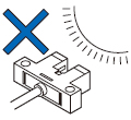
- Since the sensor is intended for use inside machines, no special countermeasures have been taken against extraneous light. Take care that extraneous light is not directly incident on the beam receiving section.
- Do not use during the initial transient time (50 ms) after the power supply is switched on.
- The cable of PM-□24-R is a flexible cable usable on a moving base. When the sensor is mounted on a moving base, fix the sensor cable joint so that stress is not applied to it. (Models other than the PM-□24-R cannot be used on a moving base.)
- Take care that the flexibility of the PM-□24-R cable is lost if the ambient temperature is -10℃ +14 ℉ or less.